A Framework for Evaluating Early-Stage Human - of Marcus Hutter
A Framework for Evaluating Early-Stage Human - of Marcus Hutter
A Framework for Evaluating Early-Stage Human - of Marcus Hutter

You also want an ePaper? Increase the reach of your titles
YUMPU automatically turns print PDFs into web optimized ePapers that Google loves.
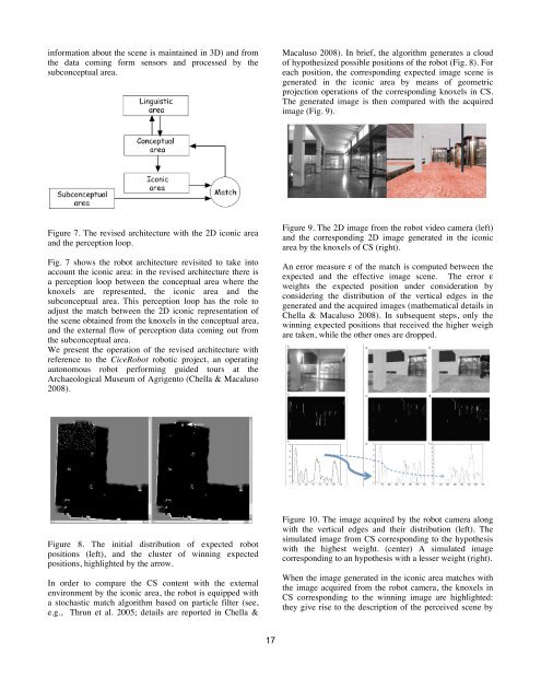
in<strong>for</strong>mation about the scene is maintained in 3D) and from<br />
the data coming <strong>for</strong>m sensors and processed by the<br />
subconceptual area.<br />
Macaluso 2008). In brief, the algorithm generates a cloud<br />
<strong>of</strong> hypothesized possible positions <strong>of</strong> the robot (Fig. 8). For<br />
each position, the corresponding expected image scene is<br />
generated in the iconic area by means <strong>of</strong> geometric<br />
projection operations <strong>of</strong> the corresponding knoxels in CS.<br />
The generated image is then compared with the acquired<br />
image (Fig. 9).<br />
Fig. 4. The 2D image output <strong>of</strong> the robot video camera (left) and the corresponding image<br />
generated by Figure the simulator 9. The (right). 2D image from the robot video camera (left)<br />
Figure 7. The revised architecture with the 2D iconic area<br />
and the corresponding 2D image generated in the iconic<br />
and the perception loop.<br />
area by the knoxels <strong>of</strong> CS (right).<br />
Fig. 4 shows the 2D image S as output <strong>of</strong> the robot video camera (left) and the<br />
Fig. 7 shows the robot architecture revisited to take into corresponding image S’ generated by the simulator (right) by re-projecting in 2D the 3D<br />
An error measure ε <strong>of</strong> the match is computed between the<br />
account the iconic area: in the revised architecture there in<strong>for</strong>mation is from the current point <strong>of</strong> view <strong>of</strong> the robot.<br />
a perception loop between the conceptual area where the The comparator<br />
expected<br />
block<br />
and<br />
c compares<br />
the effective<br />
the two<br />
image<br />
images<br />
scene.<br />
<strong>of</strong> Fig. 4 by<br />
The<br />
using<br />
error<br />
elastic<br />
ε<br />
templates<br />
weights the expected position under consideration by<br />
knoxels are represented, the iconic area and matching the [2]. In the current implementation, features are long vertical edges extracted<br />
considering the distribution <strong>of</strong> the vertical edges in the<br />
subconceptual area. This perception loop has the role from to the camera image. Spatial relations between edges’ midpoints are used to locate<br />
generated and the acquired images (mathematical details in<br />
adjust the match between the 2D iconic representation<br />
each<br />
<strong>of</strong><br />
edge in the simulated image and compute the relative distortion between the<br />
expected and Chella the effective & Macaluso scene. The 2008). relative In distortion subsequent is a measure steps, only <strong>of</strong> the the error ε related<br />
the scene obtained from the knoxels in the conceptual area,<br />
to the differences winning between expected the positions expected that image received scene the and higher the effective weigh scene. As<br />
and the external flow <strong>of</strong> perception data coming out from<br />
previously are stated, taken, this while error is the sent other back ones to the are simulator dropped. in order to correct the robot<br />
the subconceptual area.<br />
position in the 3D simulator.<br />
We present the operation <strong>of</strong> the revised architecture with<br />
reference to the CiceRobot robotic project, an operating<br />
autonomous robot per<strong>for</strong>ming guided tours at the<br />
Archaeological Museum <strong>of</strong> Agrigento (Chella & Macaluso<br />
2008).<br />
Fig. 5. The operation <strong>of</strong> the particle filter. The initial distribution <strong>of</strong> expected robot<br />
positions (left), and the cluster <strong>of</strong> winning expected positions (right).<br />
Figure 10. The image acquired by the robot camera along<br />
4 Experimental with the vertical results edges and their distribution (left). The<br />
simulated image from CS corresponding to the hypothesis<br />
Figure 8. The initial distribution <strong>of</strong> expected robot In order to with test the the proposed highest architecture weight. (center) we compared A simulated the operations image <strong>of</strong> the robot<br />
positions (left), and the cluster <strong>of</strong> winning expected equipped with corresponding the described to an system hypothesis with the with operations a lesser <strong>of</strong> weight the robot (right). driven by the<br />
positions, highlighted by the arrow.<br />
odometric in<strong>for</strong>mation only.<br />
When the image generated in the iconic area matches with<br />
In order to compare the CS content with the external<br />
the image acquired from the robot camera, the knoxels in<br />
environment by the iconic area, the robot is equipped with<br />
CS corresponding to the winning image are highlighted:<br />
a stochastic match algorithm based on particle filter (see,<br />
they give rise to the description <strong>of</strong> the perceived scene by<br />
e.g., Thrun et al. 2005; details are reported in Chella &<br />
17