APS Beamline 2-BM micro-tomography system
APS Beamline 2-BM micro-tomography system
APS Beamline 2-BM micro-tomography system

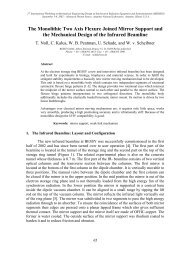
Create successful ePaper yourself
Turn your PDF publications into a flip-book with our unique Google optimized e-Paper software.
X-ray<br />
beam<br />
Robot<br />
Tweezer<br />
<strong>APS</strong> 2-<strong>BM</strong><br />
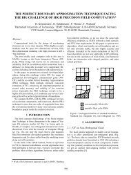
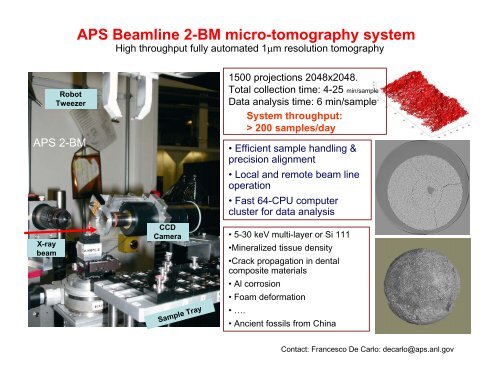
<strong>APS</strong> <strong>Beamline</strong> 2-<strong>BM</strong> <strong>micro</strong>-<strong>tomography</strong> <strong>system</strong><br />
High throughput fully automated 1μm resolution <strong>tomography</strong><br />
CCD<br />
Camera<br />
Sample Tray<br />
1500 projections 2048x2048.<br />
Total collection time: 4-25 min/sample<br />
Data analysis time: 6 min/sample<br />
System throughput:<br />
> 200 samples/day<br />
• Efficient sample handling &<br />
precision alignment<br />
• Local and remote beam line<br />
operation<br />
• Fast 64-CPU computer<br />
cluster for data analysis<br />
• 5-30 keV multi-layer or Si 111<br />
•Mineralized tissue density<br />
•Crack propagation in dental<br />
composite materials<br />
• Al corrosion<br />
• Foam deformation<br />
•….<br />
• Ancient fossils from China<br />
Contact: Francesco De Carlo: decarlo@aps.anl.gov
<strong>APS</strong> <strong>Beamline</strong> 2-<strong>BM</strong> <strong>micro</strong>-<strong>tomography</strong> <strong>system</strong><br />
Off-line Pre-alignment<br />
Standard Sample<br />
Holders<br />
High throughput fully automated 1μm resolution <strong>tomography</strong><br />
Sample Changer<br />
Scintillator<br />
Automatic Sample<br />
Changer<br />
Data handled per sample (every ~ 25 min)<br />
Pixels Gbytes<br />
CCD single projection 2,048 x 2,048 8.00 MByte<br />
Raw Data Set 2,048 x 2,048 x 1,440 11.25 GByte<br />
Normalized 2,048 x 2,048 x 1,440 22.50 GByte<br />
Reconstructed 2,048 x 2,048 x 2,048 32.00 GByte<br />
Total 73.75 GByte<br />
Data Processed 4.15 TB/day<br />
Data Distributed to users 2.43 TB/day<br />
Contact: Francesco De Carlo: decarlo@aps.anl.gov
100 μm<br />
<strong>APS</strong> <strong>Beamline</strong> 2-<strong>BM</strong> <strong>micro</strong>-<strong>tomography</strong> <strong>system</strong><br />
3D Microstructure Visualization and Modeling of Deformation in Metal Matrix Composite<br />
Particle Reinforced<br />
Metal Matrix Composites<br />
N. Chawla, Arizona State University with Alcoa, Ford, GM, and Chrysler<br />
The <strong>APS</strong> <strong>micro</strong>-<strong>tomography</strong> <strong>system</strong> will allow to make<br />
lightweight connecting rods for passenger cars by<br />
• Visualizing and quantifying the fraction and<br />
distribution of SiC, pores, and Fe-rich<br />
inclusions<br />
• Understanding the role of Fe-rich inclusions<br />
and pores on tensile and fatigue resistance<br />
of MMCs<br />
• Quantifying the degree of damage as a<br />
function of distance from the fracture plane
<strong>APS</strong> <strong>Beamline</strong> 2-<strong>BM</strong> <strong>micro</strong>-<strong>tomography</strong> <strong>system</strong><br />
New Reusable Solid Rocket Motors Insulation<br />
Mark Gentz, Alliant Tech<strong>system</strong> - ATK Launch Systems<br />
Fiber Alignment and Distribution<br />
The <strong>APS</strong> <strong>micro</strong>-<strong>tomography</strong> <strong>system</strong> allows to study:<br />
• The Reusable Solid Rocket Motors of the<br />
Space Shuttle<br />
• The new internal rocket motor insulation for<br />
NASA that is designed to replace the current<br />
asbestos fiber based insulation.<br />
Filler Size and Distribution<br />
• The characteristic of the alignment<br />
and distribution of the fibers<br />
• The particle size and distribution of<br />
the fillers for this insulation material<br />
• Materials processed under various<br />
conditions.
<strong>APS</strong> <strong>Beamline</strong> 2-<strong>BM</strong> <strong>micro</strong>-<strong>tomography</strong> <strong>system</strong><br />
Self healing composite materials <strong>micro</strong>structure and healing efficiency<br />
PI Fabrizia Ghezzo Duke University with SensorMetrix Inc. and NanoComposix Inc.<br />
2 x 2mm samples 3 layers<br />
New sample, CFRP epoxy<br />
The <strong>APS</strong> <strong>micro</strong>-<strong>tomography</strong> <strong>system</strong> allows to study:<br />
• Fibers distribution in composite laminates (quality of<br />
the fabrication process)<br />
• Presence of voids or defects into the matrix phase<br />
of the composite<br />
• Presence of cracks<br />
• Healing of cracks<br />
• If healing at temperatures close to Tg (glass<br />
transition temperature) of the polymer the material<br />
deforms (identification of creep phenomena)<br />
New (non-thermo-shocked) sample,<br />
small section, CFRP-2MEP4F<br />
Same sample, Healed over 100C (close to polymer glass<br />
transition temperature): polymer viscosity issues
Data<br />
Storage<br />
(local RAID)<br />
eSCSI<br />
gridftp<br />
MPI Server<br />
Pre-processing<br />
Sinograms<br />
Data<br />
Storage<br />
10Gb<br />
Data<br />
Acquisition<br />
System<br />
tomo or orthos<br />
MPI Clients<br />
Reconstruction<br />
Reconstruction<br />
Reconstruction<br />
Reconstruction<br />
MPI Front End &<br />
Data Distribution
Data Analysis Clusters<br />
Same VLAN and queuing <strong>system</strong><br />
• Dedicated <strong>Beamline</strong> cluster (tomo)<br />
– 8 x [2 x dual-core 2- GHz] CPU compute<br />
nodes on a Infiniband bus.<br />
– 40 TByte scalable high performance<br />
parallel file <strong>system</strong> ( )<br />
– 3D rendering: Amira<br />
– Sample reconstruction in ~ 22 min<br />
• Shared <strong>APS</strong> cluster (orthos)<br />
– 17 x [2 x dual-core 2.6- GHz]<br />
compute nodes on a Infiniband<br />
bus.<br />
– 70 TByte scalable high<br />
performance parallel file <strong>system</strong><br />
– 1 Head node - 500GB of local<br />
user space, 8GB RAM, 2 x<br />
2.6Ghz Dual Core opteron<br />
– 1 Administrative node - 250GB<br />
local user space, 8GB RAM, 2 x<br />
2.6Ghz Dual Core opteron.<br />
Fully Scalable (disk space and CPU power)
<strong>APS</strong> <strong>Beamline</strong> 2-<strong>BM</strong> <strong>micro</strong>-<strong>tomography</strong> <strong>system</strong><br />
Mechanical behavior of sand under compression through direct observation of 3D Microstructure,<br />
Jay Hanan Oklahoma State University<br />
76 <strong>tomography</strong> datasets in total for the 34%<br />
maximum strain reached.<br />
1mm<br />
4 tomographs are<br />
combined per strain<br />
step to examine the<br />
full column.<br />
2D slice of the sand grains<br />
2.6 µm/pixel resolution
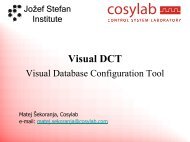
<strong>APS</strong> <strong>Beamline</strong> 2-<strong>BM</strong> <strong>micro</strong>-<strong>tomography</strong> <strong>system</strong><br />
Mechanical behavior of sand under compression through direct observation of 3D Microstructure,<br />
Jay Hanan Oklahoma State University<br />
Tomographs and simulations<br />
global strains are equal.<br />
N. P. Daphalapurkar, J. C. Hanan, et al.,<br />
“Tomography and Simulation of<br />
Microstructure Evolution of a Closed‐Cell<br />
Polymer Foam in Compression.” Mechanics<br />
of Advanced Materials and Structures,<br />
15:1–18, 2008.<br />
35<br />
30<br />
25<br />
20<br />
15<br />
10<br />
5<br />
1. 6. 3. 5. 4. 2. 7. Zero Densification<br />
Cells First Initial Densification collapse stress start flatten buckling to change shape<br />
0<br />
0.0 0.1 0.2 0.3 0.4 0.5 0.6 0.7 0.8<br />
Strain ( mm / mm )<br />
35<br />
30<br />
25<br />
20<br />
15<br />
10<br />
5<br />
0<br />
Stress (MPa)
Ultra-fast Tomography: A Bubble Growing ( 4Hz Tomography)<br />
10<br />
0 ms 1500 ms 3000 ms<br />
> 10 PB/day …..
GPU developments