The Present and Future Use of High- Energy X-rays for Industrial ...
The Present and Future Use of High- Energy X-rays for Industrial ...
The Present and Future Use of High- Energy X-rays for Industrial ...

Create successful ePaper yourself
Turn your PDF publications into a flip-book with our unique Google optimized e-Paper software.
<strong>The</strong> <strong>Present</strong> <strong>and</strong> <strong>Future</strong> <strong>Use</strong> <strong>of</strong> <strong>High</strong>-<br />
<strong>Energy</strong><br />
X-<strong>rays</strong> <strong>for</strong> <strong>Industrial</strong> Materials<br />
Research<br />
Yan Gao<br />
GE Global Research Center<br />
Niskayuna, NY 12309<br />
Workshop on “Science with <strong>High</strong>-<strong>Energy</strong> X-<strong>rays</strong>”<br />
August 9, 2004, Advanced Photon Source, ANL
Acknowledgem<br />
ent<br />
Beamlines XOR 1-ID-C, 5-BM-D<br />
Ulrich Lienert (APS)<br />
Jon Almer (APS)<br />
Peter Lee (APS)<br />
Dean Haeffner (APS)<br />
Peter Chupas (ANL)<br />
Qing Ma (DND-CAT)<br />
Beamlines X17B1, X15A<br />
Zhong Zhong (NSLS)<br />
Bill Carter (GE)<br />
Jim Ruud (GE)<br />
Tom Angeliu (GE)<br />
Kan Kump (GEMS)
Outlin<br />
e<br />
!GE <strong>and</strong> GE Global Research<br />
!<strong>The</strong> <strong>Present</strong><br />
•Residual stress measurement<br />
•Characterization <strong>of</strong> TBC<br />
•<strong>High</strong> throughput XRD <strong>and</strong> SAXS<br />
•Hg XRF at 83 keV<br />
•Pr EXAFS at 42 keV<br />
•Other applications with HE X-<strong>rays</strong><br />
!<strong>The</strong> <strong>Future</strong><br />
•Cutting-edge capability<br />
•Advanced characterization<br />
•A friendly user facility
GE <strong>and</strong> GE Global Research<br />
Niskayuna, NY<br />
India China Germany
GE Global Research: Hub <strong>for</strong><br />
innovation<br />
<strong>The</strong>n…<br />
And Now…<br />
Cutting-edge research<br />
• Nanotechnology & functional<br />
materials<br />
• Hydrogen storage materials<br />
• Solid Oxide Fuel Cell<br />
• Photovoltaics<br />
Discovery <strong>of</strong> synchrotron<br />
radiation at GE Research<br />
Center (1947)
Why is GE interested in HE X-<br />
<strong>rays</strong><br />
• Unique capability (penetrating power. intensity)<br />
• Superior data quality (S/N, angular resolution)<br />
• Productivity (simpler sample prep, fast data collection)<br />
Low-energy X-<strong>rays</strong><br />
<strong>High</strong>-energy X-<strong>rays</strong><br />
Research on many metals, alloys, <strong>and</strong> ceramics
Residual stress measurement<br />
Incident X-ray<br />
2Θ<br />
Diffracted X-<br />
ray<br />
Obtain depth pr<strong>of</strong>ile by layer<br />
removal<br />
Synchrotron X-<strong>rays</strong><br />
• Small beam size<br />
• <strong>High</strong> intensity<br />
• <strong>High</strong> accuracy<br />
• Non-destructive with HE X-<strong>rays</strong><br />
In-house X-ray source<br />
• Large beam footprint<br />
• Low intensity <strong>for</strong> high-angle peaks<br />
• Low accuracy<br />
• Layer-removal <strong>for</strong> depth pr<strong>of</strong>ile<br />
Incident X-<br />
ray<br />
Obtain depth pr<strong>of</strong>ile by moving<br />
sample<br />
Diffracted X-<br />
ray<br />
2Θ<br />
Residual Stress Determination Is Very Important <strong>for</strong> Industry
Non-destructive residual stress measurement<br />
•Shot-peening effect was measured as a function <strong>of</strong> depth<br />
•Sample stage was used to bring more grains to diffraction<br />
Obtaining triaxial strain<br />
tensor<br />
Hoop<br />
Radial<br />
Rotation: 2 rps<br />
Axial<br />
Translation: 4 mm/s<br />
Diffraction data were collected at<br />
various χ, φ <strong>and</strong> t (depth up to 1.3 mm)<br />
352 images were taken in 6 hours per<br />
sample in automated operation<br />
XOR 1-ID-C (U. Lienert)
Non-destructive residual stress measurement<br />
•Triaxial stress components determined<br />
•Affected depth up to 400 µm.<br />
Stress [MPa]<br />
200<br />
100<br />
0<br />
-100<br />
-200<br />
-300<br />
-400<br />
-500<br />
-600<br />
hoop<br />
axial<br />
radial<br />
0.00 0.20 0.40 0.60 0.80 1.00<br />
Depth [mm]
<strong>High</strong>-energy X-ray powder diffraction<br />
Combined with MarCCD <strong>and</strong> an auto sampler, high<br />
throughput measurements can be per<strong>for</strong>med .<br />
Sagittal focusing monochromator<br />
Sample (3 mm)<br />
Stage movement<br />
• Providing 10 11 ph/s at 67 keV<br />
by focusing horizontal beam<br />
from 40 mm to 0.5 mm, which<br />
is an flux increase by 2 order<br />
<strong>of</strong> magnitude.<br />
• Vertical divergence is between<br />
10-30 micro-radians good<br />
angular resolution<br />
X17B1 (Z. Zhong)
Applications to <strong>The</strong>rmal Barrier Coatings (TBC)<br />
• Polymorphs: tetragonal, cubic <strong>and</strong><br />
monoclinic<br />
• Separation <strong>of</strong> tetragonal <strong>and</strong> cubic peaks<br />
• Determination <strong>of</strong> lattice parameters <strong>and</strong><br />
c/a’: trans<strong>for</strong>mable (t) <strong>and</strong> nontrans<strong>for</strong>mable<br />
(t’)<br />
• Texture: difficult with conventional XRD.<br />
7-8YSZ<br />
YS<br />
Z<br />
Bond coat<br />
Superalloy substrate
Applications to <strong>The</strong>rmal Barrier Coatings (TBC)<br />
TBC analyses may involve large<br />
number <strong>of</strong> measurements<br />
or<br />
Time<br />
Per<strong>for</strong>mance DOE<br />
Temperature<br />
x x x<br />
x x x<br />
x x x<br />
x x x<br />
x x x<br />
• Tetra = 49.9 wt%<br />
• Cubic = 47.9 wt%<br />
• Mono = 2.2 wt%<br />
• Tetra c/a’ = 1.0154 → t’<br />
• Tetra c/a’ → 4.4 mol% YO 1.5<br />
• Tetra c/a’ → thermal history<br />
• Cubic a → 14.0 mol% YO 1.5<br />
• Peak width → micro-strain<br />
• Peak position → macro-strain
Applications to cast ODS alloys<br />
Oxide Dispersion Strengthened A<br />
Fe, Ni or Cu Nano-sized oxide<br />
(less than 1 wt%)<br />
Conventional analyses<br />
•XRD phase analysis<br />
•TEM sample: from a tiny<br />
area<br />
•SAXS sample: thin <strong>and</strong><br />
small<br />
TEM micrograph
Applications to cast ODS alloys<br />
Scan sample<br />
Transmission HE-XRD<br />
• Phase identification<br />
• Oxide dispersion in macro scale<br />
100<br />
mm<br />
Cross-section <strong>of</strong> ingot<br />
A few mm thick<br />
HE-SAXS<br />
• Oxide dispersion in micro scale<br />
• Oxide size <strong>and</strong> size distribution<br />
AlYO 3 <strong>and</strong> Al 5 Y 3 O 12
Applications to cast ODS alloys<br />
HE-SAXS<br />
• Oxide dispersion in micro scale<br />
• Oxide size <strong>and</strong> size distribution<br />
Igor + SAS macro (J. Ilavsky)<br />
Size <strong>and</strong> size distribution<br />
XOR 1-ID-C (J. Almer)
<strong>High</strong>-energy X-ray<br />
fluorescence<br />
Example: Hg K-edge<br />
Binding <strong>Energy</strong> (keV) at K edge<br />
36.0<br />
•Low Hg<br />
concentration (a<br />
few mg)<br />
•Many commonly used elements, including RE elements •Non-destructive<br />
•Excitation beyond the energy <strong>of</strong> in-house XRF •Hg vapor pressure<br />
•Greater fluorescence yield at K-edge<br />
vs. temperature<br />
•<strong>Use</strong>ful <strong>for</strong> non-destructive detection<br />
90.5
Non-destructive detection <strong>of</strong> Hg vapor in F-lamps<br />
Setup at NSLS X26A <strong>and</strong> X17B1<br />
10000<br />
Kr Kα<br />
Kr Kβ/Sr Kα<br />
Glass wall: 0.8<br />
mm<br />
Diameter: 1.5”<br />
1000<br />
100<br />
Hg Lβ<br />
Sr Kβ<br />
Ag Kα<br />
Hg Lα Zn Kβ Zn Kα<br />
Hg L α & L β lines<br />
X26A: L edge<br />
Fluorescence intensity<br />
Ar Kα<br />
Ca Kα<br />
Fe Kα<br />
Cu Kα<br />
Hg<br />
Detecto<br />
r<br />
Incident X-ray<br />
K edge = 83.1<br />
keV<br />
L 3<br />
edge = 12.3<br />
keV<br />
<strong>The</strong> lamp was wrapped with<br />
heating tape <strong>for</strong> temperaturedependent<br />
measurement<br />
Intensity<br />
5000<br />
4000<br />
3000<br />
2000<br />
1000<br />
0<br />
0 5 10 15 20 25<br />
Hg K α & K β<br />
lines<br />
Hg K α2<br />
Hg K α1<br />
<strong>Energy</strong> (keV)<br />
Pb K α2<br />
T55a<br />
T90a<br />
T123a<br />
T150a<br />
T150b<br />
66 68 70 72 74 76 78 80 82<br />
<strong>Energy</strong> (keV)<br />
X17: K edge<br />
Hg K β<br />
Pb K α1
X-ray absorption spectroscopy using HE X-<strong>rays</strong><br />
Motivation: Underst<strong>and</strong> the role <strong>of</strong> Pr doping in Quantum Splitting Ph<br />
Pr<br />
• Pr L-edge not possible due<br />
to La<br />
• Pr K-edge not possible at<br />
NSLS due to low flux at high<br />
energy<br />
Pr-<br />
O<br />
Pr-<br />
P<br />
Pr-<br />
La<br />
LaPO4:Pr<br />
K-edge data from APS 5-BM-D
Quantitative phase analysis using HE X-<strong>rays</strong><br />
0.5 mm<br />
Carbon<br />
WC/W 2<br />
C<br />
W<br />
Objective: Quantify W, WC <strong>and</strong> W 2<br />
C<br />
Tungsten absorption is too severe <strong>for</strong><br />
in-house conventional X-<strong>rays</strong><br />
Solution: <strong>High</strong>-energy XRD at 67 keV!
Non-destructive XRD using HE X-<strong>rays</strong><br />
QuPipe<br />
How does it work <strong>and</strong> why?<br />
<strong>The</strong> pipe is claimed to have<br />
several layers, <strong>and</strong> work only<br />
when it is sealed, there<strong>for</strong>e<br />
HE-XRD is the chosen<br />
technique to investigate the<br />
interior chemistry <strong>and</strong> crystal<br />
structure.<br />
Cu<br />
67 KeV X-ray in transmission mode
<strong>The</strong><br />
<strong>Future</strong><br />
Cutting-edge capability<br />
•A turnkey facility <strong>for</strong> MicroXRD <strong>and</strong> microXRF<br />
•Fast time-resolved in-situ diffraction<br />
Advanced characterization<br />
•Non-destructive residual stress<br />
•<strong>High</strong>-throughput materials screening (XRD, XRF<br />
<strong>and</strong> SAXS)<br />
A friendly user (including industrial users)<br />
facility<br />
•Dedicated instrumentation <strong>for</strong> frequently used<br />
techniques<br />
•Quick access <strong>and</strong>/or remote access<br />
•Commercialized analytical services
Microdiffraction with high spatial resolution<br />
Cross-section <strong>of</strong> a SOFC<br />
part:<br />
Consisting cathode,<br />
anode, electrolytes,<br />
interconnect, seal glass,<br />
etc.<br />
While elemental in<strong>for</strong>mation may be<br />
obtained by SEM-EDS, it’s very<br />
important to obtain crystal structure<br />
in<strong>for</strong>mation from region <strong>of</strong> interest as<br />
marked.<br />
50 µm<br />
Optical micrograph
A turnkey microdiffraction station: aim <strong>and</strong><br />
shoot<br />
Monochromatic<br />
beam <strong>for</strong><br />
polycrystalline area<br />
Sample<br />
A wavelength dispersive XRF detector can be added<br />
Interchangeable,<br />
focused white <strong>and</strong><br />
monochromatic beam <strong>of</strong><br />
a few µm across<br />
CCD Camera<br />
White beam <strong>for</strong><br />
single crystal<br />
grains<br />
2D<br />
detector<br />
Crystal structure
Fast time-resolved XRD<br />
Time resolution can be essential <strong>for</strong> mechanistic underst<strong>and</strong>ing!<br />
NaAlH 4 1/3 Na 3 AlH 6 + 2/3 Al + H 2<br />
~70 sec, 21 measurements<br />
Phase Fraction (arb. units<br />
400<br />
350<br />
300<br />
250<br />
200<br />
150<br />
100<br />
50<br />
NaAlH4<br />
Al<br />
Na3AlH6<br />
Na amorphous<br />
Al amorphous<br />
0<br />
-50<br />
0 50 100 150 200 250 300<br />
Time (seconds)<br />
XOR 1-ID-C using GE 2D detector (P. Chupas <strong>and</strong> P. Lee)
Fast time-resolved XRD with GE<br />
Detector<br />
GE detector at work at XOR 1-ID-C<br />
Photons<br />
Cesium Iodide (CsI)<br />
Light<br />
Amorphous Silicon Panel<br />
(Photodiode/Transistor Array)<br />
Electrons<br />
• Area: 41 cm x 41 cm<br />
• Pixel size: 200 µm<br />
• Readout: 41 ms <strong>for</strong> 2k x 2k (Angio)<br />
• Dynamic range: 14 bits<br />
Read Out Electronics<br />
Digital Data<br />
Contact: Ken Kump, GE Medical Systems, Ph: 262-548-4549
Advanced Characterization<br />
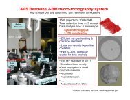
<strong>High</strong> throughput XRD measurements<br />
X-ray<br />
With automated sample stage, 2D detector, high-energy X-<strong>rays</strong>, superb<br />
synchrotron intensity, <strong>and</strong> dedicated data analysis s<strong>of</strong>tware, large number<br />
<strong>of</strong> samples can be preloaded <strong>and</strong> measured unattended or remotely. <strong>High</strong>energy<br />
X-<strong>rays</strong> in transmission mode is particularly useful <strong>for</strong> many<br />
inorganic or metallic materials.<br />
Same approach, combined with micro-focused beam, can also be<br />
used <strong>for</strong> automated diffraction mapping with monochromatic beam,<br />
or elemental mapping with white beam.
Advanced Characterization<br />
• Residual stress <strong>and</strong> plastic<br />
de<strong>for</strong>mation are very important <strong>for</strong><br />
industrial applications<br />
• Actual samples involves complex<br />
geometry, <strong>and</strong> small beam <strong>and</strong> high<br />
intensity are essential <strong>for</strong> obtaining<br />
accurate data<br />
• Non-destructive with HE X-<strong>rays</strong><br />
• Consider dedicated instrumentation<br />
<strong>and</strong> commercialize the analyses<br />
through a third party.<br />
Stress [MPa]<br />
Residual stress<br />
200<br />
100<br />
0<br />
-100<br />
-200<br />
hoop<br />
-300<br />
axial<br />
-400<br />
radial<br />
-500<br />
-600<br />
0.00 0.20 0.40 0.60 0.80 1.00<br />
Depth [mm]<br />
Plastic de<strong>for</strong>mation<br />
FWHM vs. Distance from Damaged Surface<br />
0.050<br />
0.045<br />
0.040<br />
0.035<br />
FWHM (°)<br />
0.030<br />
0.025<br />
0.020<br />
0.015<br />
0.010<br />
0.005<br />
0.000<br />
0.00 0.13 0.25 0.38 0.50 0.63 0.75 0.88 1.00<br />
Distance from surface (mm)
<strong>The</strong><br />
<strong>Future</strong><br />
A friendly user (including industrial users)<br />
facility<br />
•Dedicated instrumentation <strong>for</strong> frequently used<br />
techniques<br />
Such as powder diffraction with 2D detector <strong>for</strong><br />
normal or high throughput applications<br />
•Quick access <strong>and</strong>/or remote access<br />
Linked with dedicated instrument to minimize<br />
setup time; web-based remote access <strong>for</strong> users<br />
running experiment from home institution<br />
•Commercialized analytical services<br />
Powder diffraction <strong>and</strong> residual stress<br />
measurement may be two key areas to promote<br />
fee-based analytical services