TIG Welding of aluminum Alloys for the APS - Advanced Photon ...
TIG Welding of aluminum Alloys for the APS - Advanced Photon ...
TIG Welding of aluminum Alloys for the APS - Advanced Photon ...

Create successful ePaper yourself
Turn your PDF publications into a flip-book with our unique Google optimized e-Paper software.
<strong>TIG</strong> WELDING OF ALUMINUM ALLOYS FOR THE <strong>APS</strong><br />
STORAGE RING-A UHV APPLICATION<br />
GEORGE A. GOEPPNER<br />
Accelerator Systems Division<br />
INTRODUCTION<br />
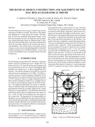
The <strong>Advanced</strong> <strong>Photon</strong> Source (<strong>APS</strong>) incorporates a 7-GeV positron storage ring<br />
1104 meters in circumference. The storage ring vacuum system is designed to<br />
maintain a pressure <strong>of</strong> 1 nTorr or less with a circulating current <strong>of</strong> 300 rnA to enable<br />
beam lifetimes <strong>of</strong> greater than 10 hours. 1 The vacuum chamber is an <strong>aluminum</strong><br />
extrusion <strong>of</strong> 6063T5 alloy. There are 235 separate <strong>aluminum</strong> vacuum chambers in<br />
<strong>the</strong> storage ring connected by stainless steel bellows assemblies. Aluminum was<br />
chosen <strong>for</strong> <strong>the</strong> vacuum chamber because it can be economically extruded and<br />
machined, has good <strong>the</strong>rmal conductivity, low <strong>the</strong>rmal emissivity, a low outgassing<br />
rate, low residual radioactivity, and is non-magnetic. The 6063 <strong>aluminum</strong>-silicon<br />
magnesium alloy provides high strength combined with good machining and<br />
weldability characteristics. The extrusion process provides <strong>the</strong> interior surface finish<br />
needed <strong>for</strong> <strong>the</strong> ultrahigh vacuum (UHV) environment. 2 There are six different vacuum<br />
chambers with <strong>the</strong> same extrusion cross section. The average vacuum chamber length<br />
is 171.6". The extruded vacuum chambers are welded to flange assemblies made up<br />
<strong>of</strong> machined 2219 <strong>aluminum</strong> alloy pieces and 2219 <strong>aluminum</strong> vacuum flanges from a<br />
commercial source.<br />
1
ALIJMINUM WELDING<br />
The main characteristics <strong>of</strong> <strong>aluminum</strong> which influence welding are hydrogen<br />
solubility, <strong>aluminum</strong> oxides, <strong>the</strong>rmal conductivity, <strong>the</strong>rmal expansion, and<br />
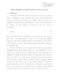
solidification shrinkage. 3 Weld porosity in <strong>aluminum</strong> is caused principally by bubbles<br />
<strong>of</strong> hydrogen that <strong>for</strong>m in <strong>the</strong> solidifying weld pool. The hydrogen solubility <strong>of</strong><br />
<strong>aluminum</strong> increases almost twenty times as <strong>the</strong> material makes <strong>the</strong> transition from<br />
solid to liquid state and continues to increase as <strong>the</strong> temperature increases (Fig. 1).<br />
Hydrogen absorbed during its molten state is <strong>for</strong>ced out <strong>of</strong> solution as <strong>the</strong> <strong>aluminum</strong><br />
cools and changes to its solid state. The hydrogen is trapped in bubbles and cannot<br />
effectively be removed from <strong>the</strong> weld. 4 As <strong>the</strong> hydrogen comes out <strong>of</strong> solution, it can<br />
be a source <strong>of</strong> porosity or voids that can connect to <strong>for</strong>m leak paths in a vacuum<br />
environment. The molten-solid hydrogen solubility ratio <strong>for</strong> <strong>aluminum</strong> is 36 times<br />
higher than <strong>for</strong> iron. This makes <strong>aluminum</strong> welds much more sensitive to this source<br />
<strong>of</strong> porosity than those <strong>of</strong> stainless steel. 5 Hydrogen contamination usually comes from<br />
moisture or oil (hydrocarbons) on <strong>the</strong> surface being welded. The parts to be welded<br />
must be cleaned well in a detergent bath and dried be<strong>for</strong>e welding.<br />
A typical layer <strong>of</strong> <strong>aluminum</strong> oxide is 25-50 A thick. Even if this is scraped away,<br />
,<br />
it will rapidly re<strong>for</strong>m to a thickness <strong>of</strong> 15A.4 Heavy layers <strong>of</strong> <strong>aluminum</strong> oxide can act<br />
like an insulator, resulting in an erratic welding arc. An <strong>aluminum</strong> oxide surface is<br />
porous and tends to trap moisture and o<strong>the</strong>r surface contaminates that lead to weld<br />
porosity.4 Aluminum oxide melts at about 3750 F (2066 C) or about three times <strong>the</strong><br />
melting point <strong>of</strong> <strong>the</strong> <strong>aluminum</strong> alloy itself.6 Since <strong>the</strong> base metal will melt long be<strong>for</strong>e<br />
<strong>the</strong> oxides, leaving a heavy oxide layer on <strong>the</strong> surface be<strong>for</strong>e welding can result in<br />
inclusions in <strong>the</strong> solidified weld zone.<br />
The <strong>the</strong>rmal conductivity <strong>of</strong> <strong>aluminum</strong> is about six times that <strong>of</strong>stee1. 6 Depending<br />
on <strong>the</strong> alloys being welded and <strong>the</strong> geometry and <strong>the</strong>rmal mass <strong>of</strong> <strong>the</strong> parts, a balance<br />
must be met between providing sufficient heat to effect a weld and excessive heat that<br />
could lead to distortion and a missed weld joint due to part movement. In <strong>the</strong> case <strong>of</strong><br />
<strong>the</strong> storage ring vacuum chamber flange assembly, <strong>the</strong> welding electrode was<br />
2
positioned 0.015" toward <strong>the</strong> 6063 material in order to compensate <strong>for</strong> <strong>the</strong> difference<br />
in <strong>the</strong>rmal conductivity between <strong>the</strong> 6063 (high <strong>the</strong>rmal conductivity) and <strong>the</strong> 2219<br />
(relatively low <strong>the</strong>rmal conductivity) materials. It was desirable to have <strong>the</strong> weld<br />
fusion zone centered on <strong>the</strong> part interface. It may also be necessary to provide a water<br />
cooled chill bar, which was required on <strong>the</strong> welding <strong>of</strong> <strong>the</strong> photon beam exit ports to<br />
<strong>the</strong> vacuum chambers. This is a long weld (8 minutes) during which <strong>the</strong> weld joint<br />
would move due to <strong>the</strong> substantial heat input and <strong>the</strong> <strong>the</strong>rmal conductivity <strong>of</strong> <strong>the</strong><br />
<strong>aluminum</strong>.<br />
The <strong>the</strong>rmal expansion <strong>of</strong> <strong>aluminum</strong> during welding, followed by solidification<br />
shrinkage, can result in cracking. Solidification shrinkage in <strong>aluminum</strong> weld metal<br />
is about 6% by volume. 6 Loads imposed by tooling can also playa part in solidification<br />
cracks. Weld crack sensitivity can be reduced by appropriate selection <strong>of</strong> <strong>the</strong> filler<br />
metal. The alloy combination <strong>of</strong> 2219 to 6063 is highly sensitive to solidification<br />
cracking unless <strong>the</strong> molten weld metal is suitably modified in its composition. 7 The<br />
feed rate <strong>of</strong> <strong>the</strong> filler wire is also an important variable which must be controlled. For<br />
<strong>the</strong> welding <strong>of</strong> <strong>the</strong> 6063 <strong>aluminum</strong> extrusion to <strong>the</strong> 2219 flange assembly, a 4043 filler<br />
wire was chosen. Typical shrinkage <strong>for</strong> this weld joint was found to be 0.012" - 0.014 11 •<br />
AUTOMATIC <strong>TIG</strong> WELDING<br />
The challenge <strong>of</strong> obtaining UHV-quality <strong>aluminum</strong> welds can be met with<br />
available technology. Careful material preparation combined with proper welding<br />
equipment and procedures will yield satisfactory results with <strong>aluminum</strong>. The arc<br />
process selected <strong>for</strong> <strong>the</strong> <strong>APS</strong> storage ring chambers was Gas Tungsten Arc <strong>Welding</strong><br />
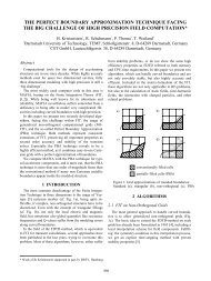
(GTAW), also know as Tungsten Inert Gas welding (<strong>TIG</strong>). This technique uses heat<br />
from an electric arc between a non-consumable tungsten electrode and <strong>the</strong> base<br />
materials to be welded (Fig. 2). Weld purity and cleanliness result because no flux is<br />
used that might cause inclusions. A filler metal was required in order to reduce<br />
sensitivity to solidification cracking. The equipment chosen, available from a<br />
4
Filler<br />
metal<br />
Base<br />
metal<br />
Filler<br />
rod<br />
HOW GTAW WORKS<br />
Base metal Weld pool Weld deposit<br />
... AND ITS EQUIPMENT SETUP<br />
Work<br />
lead<br />
Electrode lead<br />
PoINer source<br />
Figure 2. Diagram <strong>of</strong> how gas tungsten arc welding (GTAW) works. (Reprinted<br />
with permission <strong>of</strong> <strong>Welding</strong> Design and Fabrication magazine.)<br />
5
commercial supplier, had a proven per<strong>for</strong>mance record <strong>for</strong> reliability and weld quality<br />
in similar demanding <strong>aluminum</strong> welding applications. Multiple machine axis motions<br />
were required <strong>for</strong> several vacuum chamber weld joints having contoured paths. The<br />
welding torch position was programmed and controlled through closed-loop servo<br />
systems. The welding parameters were integrated with <strong>the</strong> motion programs,<br />
resulting in repeatable settings so necessary in a production environment. All welding<br />
parameters (arc voltage, weld current, wire feed speed, and axis velocity) were<br />
controlled within +/- 1% <strong>of</strong> <strong>the</strong> programmed values by real-time process monitoring.<br />
The stability <strong>of</strong> <strong>the</strong> welding arc was guaranteed by a stable and responsive Automatic<br />
Voltage Control (AVC) head which allowed precise welding torch travel normal to <strong>the</strong><br />
work while welding, in order to maintain a constant distance between <strong>the</strong> tungsten<br />
electrode and <strong>the</strong> parts being welded. All <strong>of</strong> <strong>the</strong> storage ring vacuum chamber welds<br />
were accomplished with a 200 amp power supply, although <strong>the</strong> system has recently<br />
been upgraded to 400 amps.<br />
WELDING THE <strong>APS</strong> STORAGE RING<br />
<strong>TIG</strong> welding can be done using AC <strong>TIG</strong> or DC <strong>TIG</strong>. For <strong>the</strong> storage ring vacuum<br />
chamber, DC <strong>TIG</strong> was chosen because it results in better penetration welds with a<br />
smaller Heat Affected Zone (HAZ) due to less heat input to <strong>the</strong> metal. DC <strong>TIG</strong> is also<br />
well suited to <strong>the</strong> automatic welding process. The use <strong>of</strong> inverter power supplies is<br />
<strong>of</strong>ten considered when welding <strong>aluminum</strong>. The variable polarity operation fluctuates<br />
between electrode-negative (straight) polarity and electrode-positive (reverse)<br />
polarity. The electrode-negative operation enhances penetration and narrows <strong>the</strong><br />
weld bead while <strong>the</strong> electrode-positive polarity provides a cathodic cleaning action on<br />
<strong>the</strong> <strong>aluminum</strong>. 8 The <strong>APS</strong> welding systems do not have inverter controls. Instead,<br />
each joint was hand-scraped immediately be<strong>for</strong>e welding to remove <strong>the</strong> heavy oxide<br />
layer. Cleanliness must be a high priority to obtain UHV-quality <strong>aluminum</strong> welds.<br />
Equally important is <strong>the</strong> design <strong>of</strong> <strong>the</strong> weld joint. General guidelines that should be<br />
followed when designing welded vacuum vessels include:<br />
6
1. Weld from <strong>the</strong> vacuum side if possible;<br />
2. Use full-penetration welds if welding must be done from <strong>the</strong> atmosphere<br />
side;<br />
3. Avoid gas-trapping, close-fitting surfaces that are not part <strong>of</strong> <strong>the</strong> weld zone.<br />
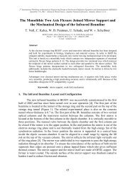
Figure 3 shows <strong>the</strong> joint design <strong>for</strong> <strong>the</strong> vacuum chamber end flange assemblies to<br />
<strong>the</strong> <strong>aluminum</strong> extrusion. This was a full-penetration DC <strong>TIG</strong> weld requiring 3-axis<br />
contoured motion from <strong>the</strong> atmosphere side. There are 470 <strong>of</strong> <strong>the</strong>se welds in <strong>the</strong><br />
storage ring. The thickness welded was approximately 0.180". U nderbead penetration<br />
into <strong>the</strong> beam chamber geometry was limited to 0.020" <strong>for</strong> rf impedance reasons. As<br />
discussed earlier, it was necessary to <strong>of</strong>fset <strong>the</strong> tungsten electrode towards <strong>the</strong> 6063<br />
extrusion in order to completely consume <strong>the</strong> joint interface in <strong>the</strong> weld zone.<br />
Figure 4 shows a 4.5" <strong>aluminum</strong> Conflat welded to both sides <strong>of</strong> <strong>the</strong> photon<br />
extraction channel <strong>of</strong> <strong>the</strong> extrusion. The top flange is <strong>for</strong> <strong>the</strong> insertion <strong>of</strong> a photon<br />
absorber; <strong>the</strong> lower flange mounts an ion pump intended <strong>for</strong> <strong>the</strong> local gas load due to<br />
<strong>the</strong> absorber. Similar features are found on each <strong>of</strong> <strong>the</strong> <strong>aluminum</strong> chambers <strong>of</strong> <strong>the</strong><br />
storage ring. This "butt joint" was welded from <strong>the</strong> inside (vacuum side) with full<br />
penetration. Note that <strong>the</strong> end <strong>of</strong> <strong>the</strong> flange weld neck was turned to a smaller<br />
diameter. This was done <strong>for</strong> two reasons: -I) to provide accurate machined surfaces <strong>of</strong><br />
<strong>the</strong> parts being welded, and 2) to allow <strong>for</strong> a full-penetration weld without putting<br />
excessive heat into <strong>the</strong> material, resulting in de<strong>for</strong>mation. It was also necessary to<br />
control heat input on all <strong>of</strong> <strong>the</strong> vacuum welds near a Conflat flange. The flange<br />
temperature could not exceed 150 degrees C to avoid tempering and loss <strong>of</strong> strength<br />
at <strong>the</strong> Conflat knife edge. Note <strong>the</strong> circumferential groove adjacent to <strong>the</strong> joint<br />
interface. This was done in all cases to better match <strong>the</strong> <strong>the</strong>rmal masses <strong>of</strong> <strong>the</strong><br />
different <strong>aluminum</strong> alloys being welded and to allow visual inspection <strong>of</strong> <strong>the</strong> weld<br />
underbead by <strong>the</strong> machine operator.<br />
The photon beam exit ports have a joint design similar to <strong>the</strong> end flanges. There<br />
are two exit ports per sector, one <strong>for</strong> insertion device (ID) radiation and one <strong>for</strong> bending<br />
magnet (BM) radiation. The ID exit port requires a 58"-long linear weld on both sides<br />
7
<strong>of</strong><strong>the</strong> interface to <strong>the</strong> chamber, while <strong>the</strong> BM exit port requires a 73"-long linear weld.<br />
These are full-penetration welds done from <strong>the</strong> atmosphere side. Because <strong>of</strong> <strong>the</strong> long<br />
length to be welded, substantial heat is absorbed by <strong>the</strong> <strong>aluminum</strong> extrusion during<br />
welding. Water-cooled chill plates were clamped to <strong>the</strong> extrusions in order to limit<br />
<strong>the</strong> movement <strong>of</strong> <strong>the</strong> weld joint <strong>of</strong>f <strong>of</strong> <strong>the</strong> pre-programmed torch electrode path.<br />
Incomplete fusion <strong>of</strong> <strong>the</strong> joint would result in a virtual leak at <strong>the</strong> least, a real leak at<br />
<strong>the</strong> worst. It was necessary to view <strong>the</strong> electrode path while welding via a television<br />
monitoring system. The machine operator had <strong>the</strong> ability, through a hand-held<br />
pendant, to input machine axis corrections in real time in order to keep <strong>the</strong> welding<br />
torch centered on <strong>the</strong> joint. This system was available from a commercial supplier<br />
and was integrated with <strong>the</strong> automatic welding machine.<br />
QUALITY ISSUES<br />
T'here are approximately 2500 <strong>aluminum</strong> welds in <strong>the</strong> <strong>APS</strong> storage ring that must<br />
provide reliable UHV integrity during machine operations. Several <strong>of</strong> <strong>the</strong> joint designs<br />
are common to each <strong>of</strong> <strong>the</strong> six different vacuum chambers, resulting in 13 different<br />
machine welding programs. Achieving high reliability with a minimum amount <strong>of</strong><br />
rework was a quality goal set early during <strong>the</strong> welding development program. The<br />
use <strong>of</strong> automatic welding systems was a step in <strong>the</strong> right direction. The requirement<br />
in design <strong>for</strong> full-penetration welds was also an early decision with quality<br />
implications. A full-penetration weld can be readily inspected visually and, while not<br />
a complete guarantee <strong>of</strong> weld quality, a complete penetration <strong>of</strong> <strong>the</strong> weld joint <strong>for</strong> <strong>the</strong><br />
full length <strong>of</strong> <strong>the</strong> interface allows a 95% confidence level that <strong>the</strong> weld is suitable <strong>for</strong><br />
a UHV application. Complete inspection must include radiographic analysis, i.e., x<br />
raying, against a standard. However, <strong>the</strong>re is no known published standard <strong>for</strong> <strong>TIG</strong><br />
welding <strong>of</strong> <strong>aluminum</strong> vacuum vessels. At <strong>the</strong> <strong>APS</strong> production facility, MIL-STD-2219<br />
<strong>for</strong> Class A welds was adopted. This was <strong>the</strong> toughest specification against which <strong>APS</strong><br />
<strong>aluminum</strong> welding per<strong>for</strong>mance could be judged. The main requirement concerns<br />
10
subsurface pores and inclusions (as seen III x-ray photographs) relative to weld<br />
thickness (T) as follows:<br />
1. Individual size must be less than 0.33T or 0.060", whichever is less.<br />
2. Spacing (<strong>of</strong> inclusions or pores) must be at least 4 times <strong>the</strong> size <strong>of</strong> <strong>the</strong><br />
larger adjacent imperfection.<br />
3. Accumulated length (<strong>of</strong> inclusions or pores) in any 3" <strong>of</strong> weld must be less<br />
than 1.33T or 0.24", whichever is less. 9<br />
Ten percent <strong>of</strong> <strong>the</strong> storage ring vacuum chambers were subjected to x-ray<br />
inspection against MIL-STD-2219, Class A, throughout <strong>the</strong> production period. No<br />
rejects against this standard were found. After some initial start-up problems, <strong>the</strong><br />
repair rate <strong>for</strong> <strong>the</strong> entire 235 vacuum chambers was approximately 3%. No chambers<br />
were scrapped as a result <strong>of</strong> a welding problem. Repairs were all done with manual<br />
<strong>TIG</strong> welding which was found to be more efficient than setting up <strong>the</strong> chambers a<br />
second time on <strong>the</strong> tooling <strong>of</strong> <strong>the</strong> automatic systems.<br />
This level <strong>of</strong> production per<strong>for</strong>mance was <strong>the</strong> result <strong>of</strong> high quality standards<br />
employed during cleaning, welding, assembly, and vacuum leak testing. Cleaning <strong>of</strong><br />
<strong>the</strong> <strong>aluminum</strong> vacuum chambers has been well documented by o<strong>the</strong>rs. IO Assembly<br />
was per<strong>for</strong>med in a clean room. Each vacuum chamber was leak tested by pumping<br />
with turbo pumps, ion pumps, and NeG strip activation, with two <strong>the</strong>rmal cycles to<br />
150 degrees C. On achieving a certification pressure <strong>of</strong> 2 x 10- 10 Torr or better, <strong>the</strong><br />
chamber was considered acceptable <strong>for</strong> use in <strong>the</strong> <strong>APS</strong> storage ring.<br />
There were numerous quality standards demanded <strong>of</strong> welding system ancillaries.<br />
The weld filler wire was purchased "shaved," i.e., drawn through a die that removes<br />
surface oxides and inclusions just prior to <strong>the</strong> wire being wound on a spool and<br />
hermetically sealed. The wire spool container on <strong>the</strong> welding machine had inert gas<br />
constantly purged through <strong>the</strong> wirefeed system. The 75% heliuml25% argon shielding<br />
gas used from a bulk supply was ultrahigh purity gas (99.999%) and was constantly<br />
monitored at <strong>the</strong> machine gas box <strong>for</strong> moisture content. Additionally, <strong>the</strong> welding<br />
machine control provided quality assurance through data logger s<strong>of</strong>tware, which<br />
11
collects actual welding parameters from feedback systems, displays it against preset<br />
values, and provides a hard copy <strong>for</strong> reference.<br />
WELD INTEGRITY TESTING<br />
Two 6" <strong>aluminum</strong> Conflat-to-transition-piece weld assemblies were destructively<br />
tested as a means to fur<strong>the</strong>r validate <strong>the</strong> automatic welding process. They carried<br />
production tracking numbers 4607 and 4618. These were production pieces having a<br />
butt-welded joint geometry similar to most <strong>of</strong> <strong>the</strong> joint designs on <strong>the</strong> storage ring<br />
vacuum chambers. The two assemblies were x-rayed and found to be acceptable. They<br />
were <strong>the</strong>n leak tested to 1.3 x 10- 11 atm cels helium and passed. Then both assemblies<br />
were <strong>the</strong>rmal cycled to 150 degrees C using heat tapes and held at that temperature<br />
<strong>for</strong> 10 minutes. The temperature was <strong>the</strong>n ramped down to ambient using a water<br />
chiller. Each <strong>the</strong>rmal cycle required approximately 90 minutes. Both assemblies<br />
were subjected to 50 cycles.<br />
Assemblies 4607 and 4618 were <strong>the</strong>n leak tested again and passed. Then both<br />
were x-rayed again; no changes were found when compared to <strong>the</strong> films taken<br />
previously. Each assembly was <strong>the</strong>n cut up into 12 pieces <strong>for</strong> metallographic<br />
examination and labeled 4607-1 through 12 and 4618-1 through 12. An independent<br />
lab was used <strong>for</strong> metallographic evaluation <strong>of</strong> <strong>the</strong> 24 samples. The results indicated<br />
that one sample, 4607-1, showed two discontinuities (micropores). All o<strong>the</strong>r samples<br />
showed no discontinuities, including cracks, microcracks, or inclusions, as per MIL<br />
STD-2219, section 5.4.4, Weld Quality.ll The 24 samples were finally tensile tested,<br />
with <strong>the</strong> results shown in Table 1.<br />
12
Table 1: Results <strong>of</strong> Metallographic Evaluation<br />
4607 4618<br />
No. Actual Theo. Actual Theo.<br />
No.<br />
(lbs) (lbs) (lbs) (lbs)<br />
-1 1000 1400 -1 1175 1500<br />
-2 850 1500 -2 1150 1312<br />
-3 425 562 -3 1125 1312<br />
-4 1675 1312 -4 1325 1500<br />
-5 1450 1312 -5 1000 1312<br />
-6 1575 1312 -6 1625 1500<br />
-7 1725 1218 -7 1500 1400<br />
-8 867 1312 -8 1750 1312<br />
-9 1700 1500 -9 1750 1500<br />
-10 875 1125 -10 900 1500<br />
-11 1625 1500 -11 2150 1400<br />
-12 2050 1400 -12 2450 1640<br />
Total 15625 17900 17187<br />
NOTE: Theoretical tensile strength based on 25,000 psi<br />
ultimate yield strength <strong>for</strong> 2219 <strong>aluminum</strong> calculated <strong>for</strong> area<br />
<strong>of</strong> sample specimen.<br />
13
ACKNOWLEDGEMENT<br />
Thanks to Joseph Gagliano and John Noonan <strong>for</strong> reviewing this Light Source Note<br />
prior to distribution and to <strong>the</strong> Vacuum Group technicians <strong>for</strong> a successful construction<br />
program.<br />
REFERENCES<br />
1. R. C. Niemann et al., "<strong>APS</strong> Storage Ring Vacuum System," AlP Conference<br />
Proceedings No. 236, American Vacuum Society Series 12, Argonne, IL, 1990.<br />
2. R. B. Wehrle, R. W. Nielsen, "Design <strong>for</strong> <strong>APS</strong> 7 GeV Storage Ring Vacuum<br />
System at ANL," AlP Conference Proceedings No. 171, American Vacuum<br />
Society Series 5, Upton, NY, 1988.<br />
3. P. Dickerson, B. Irving, "<strong>Welding</strong> Aluminum: It's NotAs Difficult As It Sounds,"<br />
<strong>Welding</strong> Journal, p. 48, April 1992.<br />
4. W. Tuttle, "Understanding Aluminum <strong>Welding</strong>," <strong>Welding</strong> Journal, p. 43,<br />
February 1991.<br />
5. J. Garner, "Aluminum Based Vacuum Systems," HVT, Academic Press,<br />
Harcourt Brace & Company, section 4.5.6.7, to be published.<br />
6. P. Dickerson, B. Irving, op.cit., 49.<br />
7. W. J. Farrell, Argonne National Laboratory, private communication, Sept.<br />
1992.<br />
8. A. Cullison, "Modernization Program Features Unique GTA <strong>Welding</strong><br />
Operation," <strong>Welding</strong> Journal, p. 56, December 1990.<br />
9. MIL-STD-2219, "Fusion <strong>Welding</strong> For Aerospace Applications," U.S.<br />
Department <strong>of</strong> Defense, Table 5-4, December 1990.<br />
14
10. "<strong>Advanced</strong> <strong>Photon</strong> Source Accelerator Ultrahigh Vacuum Guide," C. Liu, J.<br />
Noonan, ANU<strong>APS</strong>frB-16, March, 1994; National Technical In<strong>for</strong>mation<br />
Service, U.S. Department <strong>of</strong> Commerce.<br />
11. J. Gagliano, Argonne National Laboratory, private communication, August<br />
1993.<br />
15