TE-6001 Hardware Assemblies for TE-6000 Temperature Elements
TE-6001 Hardware Assemblies for TE-6000 Temperature Elements
TE-6001 Hardware Assemblies for TE-6000 Temperature Elements

Create successful ePaper yourself
Turn your PDF publications into a flip-book with our unique Google optimized e-Paper software.
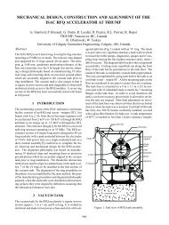
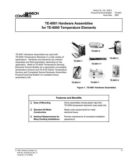
<strong>TE</strong>-<strong>6001</strong> <strong>Hardware</strong> <strong>Assemblies</strong> are used with<br />
<strong>TE</strong>-<strong>6000</strong> <strong>Temperature</strong> <strong>Elements</strong> in a wide variety of<br />
applications. <strong>Hardware</strong> and elements are ordered<br />
separately and field assembled, depending on the<br />
application. Refer to <strong>TE</strong>-<strong>6000</strong> <strong>Temperature</strong> Sensing<br />
<strong>Elements</strong> Product Bulletin <strong>for</strong> a description of available<br />
temperature sensors and <strong>TE</strong>-6100 Series <strong>Temperature</strong><br />
Sensors and Completed Sensor/<strong>Hardware</strong> <strong>Assemblies</strong><br />
Product/Technical Bulletin <strong>for</strong> available factory<br />
assembled units.<br />
<strong>TE</strong>-<strong>6001</strong>-1<br />
<strong>TE</strong>-<strong>6001</strong>-4<br />
Features and Benefits<br />
FANs 216, 125, 1628.3<br />
Product/Technical Bulletin <strong>TE</strong>-<strong>6001</strong><br />
Issue Date 0897<br />
<strong>TE</strong>-<strong>6001</strong>-2<br />
<strong>TE</strong>-<strong>6001</strong>-11<br />
<strong>TE</strong>-<strong>6001</strong>-7<br />
<strong>TE</strong>-<strong>6001</strong>-3<br />
<strong>TE</strong>-<strong>6001</strong>-6<br />
Figure 1: <strong>TE</strong>-<strong>6001</strong> <strong>Hardware</strong> <strong>Assemblies</strong><br />
❑ Ease of Mounting Some assemblies include plastic clips that<br />
<strong>TE</strong>-<strong>6000</strong> temperature elements snap easily into<br />
❑ Standard All Metal<br />
Construction<br />
<strong>TE</strong>-<strong>6001</strong> <strong>Hardware</strong> <strong>Assemblies</strong><br />
<strong>for</strong> <strong>TE</strong>-<strong>6000</strong> <strong>Temperature</strong> <strong>Elements</strong><br />
❑ Identical Replacements <strong>for</strong><br />
Many Existing Installations<br />
Meets code requirements <strong>for</strong> metal<br />
electrical boxes<br />
Permits maintenance of consistent installation<br />
appearance<br />
© 1997 Johnson Controls, Inc. 1<br />
Part No. 24-4034-34, Rev. C<br />
Code No. LIT-216300
Applications<br />
<strong>TE</strong>-<strong>6001</strong>-1<br />
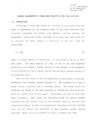
The <strong>TE</strong>-<strong>6001</strong>-1 Duct <strong>Temperature</strong> Element Holder is<br />
used with <strong>TE</strong>-<strong>6000</strong> elements in duct insertion<br />
applications. The <strong>TE</strong>-<strong>6001</strong>-1 is designed to hold<br />
one or two temperature sensors. A handi-box is<br />
supplied with the element holder.<br />
2-3/16<br />
55<br />
4-3/16<br />
106<br />
9-3/16<br />
233<br />
Figure 2: <strong>TE</strong>-<strong>6001</strong>-1 Duct Insertion Element Holder<br />
with Handi-box Dimensions (in./mm)<br />
13/16<br />
20.5<br />
17/32<br />
13.5<br />
13/16<br />
20.5<br />
13/16<br />
20.5<br />
1/4<br />
6<br />
1-3/32<br />
27.5<br />
2-3/16<br />
55<br />
1-1/16<br />
27<br />
Holes (4)<br />
Knockout <strong>for</strong><br />
1/2 in. Conduit<br />
(Top and Bottom)<br />
Knockouts <strong>for</strong><br />
1/2 in. Conduit<br />
(Both Sides)<br />
17/32<br />
13.5<br />
1-1/16<br />
27<br />
4-3/16<br />
106<br />
13/16<br />
20.5<br />
2-1/8<br />
54 13/16<br />
20.5<br />
2 <strong>TE</strong>-<strong>6001</strong> <strong>Hardware</strong> <strong>Assemblies</strong> <strong>for</strong> <strong>TE</strong>-<strong>6000</strong> <strong>Temperature</strong> <strong>Elements</strong> Product/Technical Bulletin<br />
13/16<br />
20.5<br />
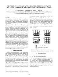
Figure 3: <strong>TE</strong>-<strong>6001</strong>-1 and -3 Dimensions (in./mm)<br />
<strong>TE</strong>-<strong>6001</strong>-2<br />
The <strong>TE</strong>-<strong>6001</strong>-2 is a metal housing used with a<br />
<strong>TE</strong>-<strong>6000</strong> <strong>Temperature</strong> Element in applications<br />
requiring outside air temperature sensing. A factory<br />
mounted plastic clip is provided to hold the <strong>TE</strong>-<strong>6000</strong><br />
sensor in place.<br />
4-1/2<br />
114<br />
7/8<br />
22<br />
1-5/16<br />
33<br />
1-1/4<br />
32<br />
1-5/16<br />
33<br />
Figure 4: <strong>TE</strong>-<strong>6001</strong>-2 Dimensions (in./mm)<br />
<strong>TE</strong>-<strong>6001</strong>-3<br />
The <strong>TE</strong>-<strong>6001</strong>-3 Handi-box (includes packing nut and<br />
fittings) is used with WZ-1000-2, -4, and -5<br />
Immersion Wells to house <strong>TE</strong>-<strong>6000</strong> elements in well<br />
insertion applications.<br />
6-1/2<br />
165<br />
1-3/8<br />
35<br />
5-1/8<br />
130<br />
1<br />
25.4<br />
5/8<br />
16<br />
1/2<br />
13<br />
1/2<br />
14 NPT<br />
13<br />
Figure 5: WZ-1000-2 and -4<br />
Dimensions (in./mm)
4-11/16<br />
119<br />
2-5/16<br />
59<br />
2-3/8<br />
60<br />
7/8<br />
22<br />
1/2 in.<br />
14 NPT<br />
19/64<br />
7.5<br />
3/8<br />
9.5<br />
Figure 6: WZ-1000-5 Dimensions (in./mm)<br />
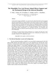
<strong>TE</strong>-<strong>6001</strong>-4<br />
The <strong>TE</strong>-<strong>6001</strong>-4 <strong>Temperature</strong> Element Holder is used<br />
with <strong>TE</strong>-<strong>6000</strong> sensors in room temperature sensing<br />
applications. The <strong>TE</strong>-<strong>6001</strong>-4 can hold up to<br />
two temperature sensors. A mounting bracket and<br />
wallplate adaptor are supplied.<br />
Note: A T-4000 cover is required and must be<br />
ordered separately. (See Table 1 <strong>for</strong><br />
ordering in<strong>for</strong>mation.)<br />
2-3/32<br />
53<br />
3-1/8<br />
79<br />
Clearance: Allow<br />
3-1/2 in. (89 mm) each<br />
side <strong>for</strong> cover screw<br />
removal with<br />
T-4000 Allen wrench.<br />
4-1/2<br />
114<br />
1/16 in.<br />
Allen-head Screw<br />
(Each Side)<br />
2-3/4<br />
70<br />
1-13/16<br />
46<br />
Figure 7: <strong>TE</strong>-<strong>6001</strong>-4 Dimensions (in./mm)<br />
1/8<br />
3<br />
Table 1: T-4000 Plastic Covers <strong>for</strong><br />
<strong>TE</strong>-<strong>6001</strong>-4 <strong>Assemblies</strong><br />
Product<br />
Code<br />
Number<br />
Horizontal<br />
Description<br />
T-4000-2139 without Setpoint Window or<br />
Thermometer, with Johnson Controls<br />
Logo, Silver Faceplate<br />
T-4000-2140 without Setpoint Window, with F/C<br />
Thermometer and Johnson Controls<br />
Logo, Silver Faceplate<br />
T-4000-2639 Concealed Setpoint, without<br />
Thermometer, with Johnson Controls<br />
Logo, Gold Faceplate<br />
T-4000-2640 Concealed Setpoint, with<br />
Thermometer and Johnson Controls<br />
Logo, Gold Faceplate<br />
Horizontal or Vertical<br />
T-4000-2138 without Setpoint Window,<br />
Thermometer, or Johnson Controls<br />
Logo, Silver Faceplate<br />
Vertical<br />
T-4000-2144 without Setpoint Window or<br />
Thermometer, with Johnson Controls<br />
Logo, Silver Faceplate<br />
<strong>TE</strong>-<strong>6001</strong>-5<br />
The <strong>TE</strong>-<strong>6001</strong>-5 Dew Point Sensor Kit is used to seal<br />
a <strong>TE</strong>-<strong>6000</strong> 1000 ohm sensor inside a Foxboro 2761<br />
Dewcel®. The kit consists of a packing nut adaptor,<br />
packing gland, washer, and packing nut.<br />
<strong>TE</strong>-<strong>6001</strong>-6<br />
<strong>TE</strong>-<strong>6001</strong>-6 Adhesive Mounting Pads are used to attach<br />
<strong>TE</strong>-<strong>6000</strong> sensors to T-4100 and T-4110 Pneumatic<br />
Room Thermostats. This provides a means of<br />
electronic temperature indication. (See Figure 1.)<br />
<strong>TE</strong>-<strong>6001</strong>-7<br />
<strong>TE</strong>-<strong>6001</strong>-7 Mounting Clips are used to attach<br />
<strong>TE</strong>-<strong>6000</strong> sensors to single setpoint T-4002 and<br />
T-4003 thermostats, H-4100 humidistats, and<br />
H-5100 humidity transmitters. This provides a<br />
means of electronic temperature indication on<br />
pneumatic room devices. (See Figure 1.)<br />
<strong>TE</strong>-<strong>6001</strong> <strong>Hardware</strong> <strong>Assemblies</strong> <strong>for</strong> <strong>TE</strong>-<strong>6000</strong> <strong>Temperature</strong> <strong>Elements</strong> Product/Technical Bulletin 3
<strong>TE</strong>-<strong>6001</strong>-8<br />
The <strong>TE</strong>-<strong>6001</strong>-8 Mounting Bracket is used with<br />
<strong>TE</strong>-6100 and <strong>TE</strong>-6300 averaging sensors to maintain<br />
the minimum bend radius recommended <strong>for</strong> these<br />
sensors. It mounts to ductwork with a single sheet<br />
metal screw.<br />
Figure 8: <strong>TE</strong>-<strong>6001</strong>-8 Dimensions (in./mm)<br />
<strong>TE</strong>-<strong>6001</strong>-11<br />
The <strong>TE</strong>-<strong>6001</strong>-11 Duct <strong>Temperature</strong> Element Holder<br />
is used with <strong>TE</strong>-<strong>6000</strong> sensors. It has a rigid<br />
aluminum support that extends in the duct to hold<br />
one or two <strong>TE</strong>-<strong>6000</strong> temperature sensing elements.<br />
Figure 9: <strong>TE</strong>-<strong>6001</strong>-11 Dimensions (in./mm)<br />
4 <strong>TE</strong>-<strong>6001</strong> <strong>Hardware</strong> <strong>Assemblies</strong> <strong>for</strong> <strong>TE</strong>-<strong>6000</strong> <strong>Temperature</strong> <strong>Elements</strong> Product/Technical Bulletin<br />
1<br />
25<br />
1/2<br />
13<br />
1/2<br />
13<br />
1-1/2<br />
38<br />
1<br />
25<br />
1/2<br />
13<br />
3/4<br />
19<br />
3/4<br />
19<br />
1-1/2<br />
38<br />
Figure 10: Hole Pattern <strong>for</strong> Installation<br />
of <strong>TE</strong>-<strong>6001</strong> -1 and -11 (in./mm)<br />
<strong>TE</strong>-<strong>6001</strong>-961 and -962<br />
The <strong>TE</strong>-<strong>6001</strong>-961 Momentary Pushbutton Switch is<br />
designed <strong>for</strong> use with the C210A-1 VAV Controller or<br />
the C260A-1 Heat Pump Controller.<br />
The <strong>TE</strong>-<strong>6001</strong>-962 Maintained Toggle Switch is used<br />
with either networked or standalone controllers to<br />
place the zone controller in the occupied mode. The<br />
<strong>TE</strong>-<strong>6001</strong>-962 is wired directly to the unoccupied<br />
terminal on the controller.<br />
<strong>TE</strong>-<strong>6001</strong>-961 and -962 switches are used with either<br />
the <strong>TE</strong>-6100-960 or <strong>TE</strong>-6100-961 room temperature<br />
sensing assemblies, which must be ordered separately.<br />
M ounting<br />
<strong>TE</strong>-<strong>6001</strong>-1 and -11<br />
The <strong>TE</strong>-<strong>6001</strong>-1 and -11 assemblies should be<br />
attached to ducts with No. 6 sheet metal screws.<br />
Both assemblies have factory mounted plastic clips<br />
that <strong>TE</strong>-<strong>6000</strong> temperature elements easily snap into.<br />
Route element leads through the bracket opening.<br />
<strong>TE</strong>-<strong>6001</strong>-2<br />
The <strong>TE</strong>-<strong>6001</strong>-2 should be mounted where the effects<br />
of sunlight and radiant heat are minimal. The<br />
housing is threaded to fit 1/2 inch rigid conduit.<br />
Seal-off fittings must be used to prevent<br />
condensation on the element or in the housing.
<strong>TE</strong>-<strong>6001</strong>-3<br />
The <strong>TE</strong>-<strong>6001</strong>-3 packing nut and fittings are used with<br />
WZ-1000-2 and -5 wells. These wells are factory<br />
filled with thermal compound <strong>for</strong> maximum<br />
conductivity.<br />
IMPORTANT: To prevent condensation of<br />
moisture in the well and failure of<br />
the element, apply plumber’s<br />
putty or some other suitable<br />
sealant (such as silicon rubber<br />
sealant) around the packing nut<br />
adaptor as well as the point<br />
where the two sensor leads pass<br />
through the adaptor.<br />
Note: See Figures 11 and 12 <strong>for</strong> proper positioning<br />
of the <strong>TE</strong>-<strong>6000</strong> sensor.<br />
Packing Nut<br />
Packing Gland<br />
<strong>TE</strong>-<strong>6000</strong><br />
Sensor<br />
Spanner Nut<br />
(Screw tight against<br />
thread relief on<br />
packing nut adaptor.)<br />
Washer<br />
Packing Nut<br />
Adaptor<br />
Handi-box<br />
W ell Assembly<br />
WZ-1000-2 or -4<br />
Figure 11: <strong>TE</strong>-<strong>6001</strong>-3 and WZ-1000-2, -4 Assembly<br />
(with <strong>TE</strong>-<strong>6000</strong> Sensor)<br />
1/2 in. NPS<br />
Star Nut<br />
(Screw tight<br />
against<br />
thread relief<br />
on adaptor.)<br />
Set Screws<br />
(Tighten onto<br />
mating groove<br />
in adaptor.)<br />
Adaptor<br />
Handi-box<br />
Grey Spacer<br />
<strong>TE</strong>-<strong>6000</strong><br />
<strong>Temperature</strong><br />
Sensor<br />
Im mersion Well<br />
WZ-1000-5<br />
Figure 12: <strong>TE</strong>-<strong>6001</strong>-3 and WZ-1000-5 Assembly<br />
(with <strong>TE</strong>-<strong>6000</strong> Sensor)<br />
<strong>TE</strong>-<strong>6001</strong>-4<br />
Mount the <strong>TE</strong>-<strong>6001</strong>-4 assembly on a wall where air<br />
is free to circulate around the elements, but away<br />
from nonrepresentative air conditions such as drafts<br />
or heat radiation. Mount the assembly 5 to 6 feet<br />
(1.5 to 1.8 m) above the floor on a standard electrical<br />
wallbox. Two factory mounted plastic clips are<br />
provided to hold the <strong>TE</strong>-<strong>6000</strong> elements. Route<br />
element leads through the bracket opening. (See<br />
Figure 13.)<br />
<strong>TE</strong>-<strong>6001</strong> <strong>Hardware</strong> <strong>Assemblies</strong> <strong>for</strong> <strong>TE</strong>-<strong>6000</strong> <strong>Temperature</strong> <strong>Elements</strong> Product/Technical Bulletin 5
<strong>TE</strong>-<strong>6001</strong>-5<br />
T-4000<br />
Cover<br />
<strong>TE</strong>-<strong>6001</strong>-4 Element<br />
Holder with<br />
<strong>TE</strong>-<strong>6000</strong> Element<br />
No. 6-32 x 1/4 in.<br />
Flat-head Screws*<br />
No. 6-32 x 7/8 in.<br />
Pan-head Screws*<br />
To install the <strong>TE</strong>-<strong>6001</strong>-5 Dew Point Sensor Kit:<br />
1. Moisten the Dewcel element with lithium chloride<br />
salt upon initial installation or after washing of<br />
the element.<br />
2. Install the Dewcel in the duct, connect to<br />
VQ-5000 power supply, and wait at least<br />
20 minutes <strong>for</strong> the Dewcel to stabilize.<br />
3. Install the <strong>TE</strong>-<strong>6000</strong> sensor as shown in<br />
Figure 14.<br />
White Leads<br />
of <strong>TE</strong>-<strong>6000</strong><br />
Mounting Bracket*<br />
Wallplate Adaptor*<br />
Figure 13: <strong>TE</strong>-<strong>6001</strong>-4 Assembly Mounting Detail<br />
Packing Nut Adaptor*<br />
Packing Gland*<br />
Washer*<br />
Packing Nut*<br />
*All are part of<br />
<strong>TE</strong>-<strong>6000</strong> kit.<br />
Power Supply<br />
Leads<br />
Conduit Box<br />
*Supplied with <strong>TE</strong>-<strong>6001</strong>-4<br />
! CAUTION: Equipment Damage Hazard.<br />
Do not immediately insert the<br />
<strong>TE</strong>-<strong>6000</strong> sensor into the Dewcel<br />
element. <strong>Temperature</strong>s in the<br />
Dewcel cavity may initially rise<br />
above the upper ambient<br />
temperature limit of the<br />
<strong>TE</strong>-<strong>6000</strong> sensor, 250°F (121°C),<br />
as the Dewcel attempts to reach<br />
equilibrium temperature.<br />
<strong>TE</strong>-<strong>6000</strong>-100<br />
<strong>Temperature</strong> Sensor<br />
Figure 14: <strong>TE</strong>-<strong>6001</strong>-5 Foxboro Dewcel Assembly<br />
Dewcel Element<br />
6 <strong>TE</strong>-<strong>6001</strong> <strong>Hardware</strong> <strong>Assemblies</strong> <strong>for</strong> <strong>TE</strong>-<strong>6000</strong> <strong>Temperature</strong> <strong>Elements</strong> Product/Technical Bulletin
<strong>TE</strong>-<strong>6001</strong>-6<br />
A <strong>TE</strong>-<strong>6001</strong>-6 Adhesive Mounting Pad is used to<br />
attach a <strong>TE</strong>-<strong>6000</strong> sensor to a T-4100 thermostat.<br />
When mounting, make certain that the sensor does<br />
not restrict the setpoint adjustment.<br />
On T-4110 thermostats, affix the sensor on the<br />
mounting plate or on the aspirator cover if an<br />
aspirator is used.<br />
<strong>TE</strong>-<strong>6001</strong>-7<br />
The <strong>TE</strong>-<strong>6001</strong>-7 Mounting Clips snap onto a<br />
pneumatic controller on the side opposite the dial (on<br />
side opposite test point <strong>for</strong> H-5100). (See Figure 1.)<br />
Pull the <strong>TE</strong>-<strong>6000</strong> element leads around the side of<br />
the instrument and through the mounting bracket<br />
opening. If a terminal connector is used on the<br />
mounting bracket, route the leads through the slot at<br />
the bottom of the connector or through the unused<br />
hole of the connector if a 3-pipe controller is not<br />
used. If a wallbox is used, the leads may also be run<br />
through a spare hole in the bracket itself.<br />
<strong>TE</strong>-<strong>6001</strong>-8<br />
Attach the <strong>TE</strong>-<strong>6001</strong>-8 Mounting Bracket to ducts with<br />
a No. 6 sheet metal screw. (See Figure 8.)<br />
The <strong>TE</strong>-<strong>6001</strong>-961 (shown)<br />
or <strong>TE</strong>-<strong>6001</strong>-962 Switch Kit <strong>for</strong> use<br />
with <strong>TE</strong>-6100-960 and -961<br />
has to be ordered separately.<br />
Room<br />
Sensing Element<br />
Assembly<br />
T-4000<br />
Cover<br />
No. 6-32 x 7/8 in.<br />
Pan-head Screws<br />
No. 6-32 x 1/4 in.<br />
Flat-head Screws<br />
<strong>TE</strong>-<strong>6001</strong>-961 and -962<br />
The <strong>TE</strong>-<strong>6001</strong>-961 and -962 are furnished with a<br />
No. 6-32 x 1/8 in. pan-head screw <strong>for</strong> mounting the<br />
switches to the <strong>TE</strong>-6100-960 or -961. (See<br />
Figure 15 <strong>for</strong> proper positioning of the <strong>TE</strong>-<strong>6001</strong>-961<br />
and -962.) Depressing the pushbutton on the<br />
<strong>TE</strong>-<strong>6001</strong>-961 connects blue to white/yellow.<br />
Pushing the <strong>TE</strong>-<strong>6001</strong>-962 toggle switch to the right<br />
(front view) connects white/yellow to blue, and<br />
pushing the switch to the left connects blue to<br />
white/orange.<br />
Wiring<br />
! CAUTION: Equipment Damage Hazard.<br />
Check all wiring connections<br />
be<strong>for</strong>e applying power to the<br />
system. Short circuited or<br />
improperly connected wires<br />
will result in permanent<br />
damage to the equipment.<br />
IMPORTANT: Make all wiring connections in<br />
accordance with the National<br />
Electrical Code and all local<br />
regulations.<br />
Wallplate Adaptor<br />
Figure 15: <strong>TE</strong>-6100-960 and -961 Mounting Detail<br />
(with <strong>TE</strong>-<strong>6001</strong>-961 Switch)<br />
Conduit Box<br />
Mounting Bracket<br />
<strong>TE</strong>-<strong>6001</strong> <strong>Hardware</strong> <strong>Assemblies</strong> <strong>for</strong> <strong>TE</strong>-<strong>6000</strong> <strong>Temperature</strong> <strong>Elements</strong> Product/Technical Bulletin 7
Table 2: Dewcel to Dew Point<br />
<strong>Temperature</strong>s<br />
Dewcel<br />
<strong>Temperature</strong><br />
Resistance<br />
(ohms)<br />
Dew Point<br />
<strong>Temperature</strong><br />
°F °C °F °C<br />
93 34 1069 30 -1<br />
99 37 1087 35 2<br />
106 41 1108 40 4<br />
112 44 1127 45 7<br />
119 48 1149 50 10<br />
127 53 1174 55 13<br />
134 57 1196 60 16<br />
141 61 1219 65 18<br />
149 65 1245 70 21<br />
156 69 1268 75 24<br />
163 73 1291 80 27<br />
171 77 1318 85 29<br />
179 82 1345 90 32<br />
188 87 1375 95 35<br />
196 91 1403 100 38<br />
Specifications<br />
Table 3: Models<br />
<strong>TE</strong>-<strong>6001</strong>- Description<br />
Product <strong>TE</strong>-<strong>6001</strong> <strong>Hardware</strong> <strong>Assemblies</strong> <strong>for</strong> <strong>TE</strong>-<strong>6000</strong> <strong>Temperature</strong> <strong>Elements</strong><br />
1 Duct <strong>Temperature</strong> Element Holder<br />
with Handi-box<br />
2 Housing <strong>for</strong> Outside Air <strong>Temperature</strong><br />
Sensing Element<br />
3 Handi-box, Packing Nut, and Fittings<br />
<strong>for</strong> Use with WZ-1000 Wells<br />
4 Single/Dual Element Holder <strong>for</strong> <strong>TE</strong>-<strong>6000</strong><br />
<strong>Elements</strong> in Room <strong>Temperature</strong> Sensing<br />
Applications<br />
5 Dew Point Sensor Kit<br />
6 Ten Adhesive Mounting Pads <strong>for</strong> Use with<br />
T-4100, T-4110<br />
7 Ten Clips <strong>for</strong> Use with T-4002/4003 and<br />
H-4100/5100<br />
8 Mounting Bracket <strong>for</strong> Use with <strong>TE</strong>-6100 and<br />
<strong>TE</strong>-6300 Averaging Sensors<br />
11 Duct <strong>Temperature</strong> Element Holder<br />
(Less Handi-box)<br />
961 Momentary Pushbutton Switch<br />
962 Maintained Toggle Switch<br />
Shipping Weight <strong>TE</strong>-<strong>6001</strong>-1: 1.3 lb (0.590 kg)<br />
<strong>TE</strong>-<strong>6001</strong>-2: 0.5 lb (0.227 kg)<br />
<strong>TE</strong>-<strong>6001</strong>-3: 1.0 lb (0.454 kg)<br />
<strong>TE</strong>-<strong>6001</strong>-4: 0.5 lb (0.227 kg)<br />
<strong>TE</strong>-<strong>6001</strong>-5: 0.3 lb (0.136 kg)<br />
<strong>TE</strong>-<strong>6001</strong>-6: 0.2 lb (0.091 kg)<br />
<strong>TE</strong>-<strong>6001</strong>-7: 0.2 lb (0.091 kg)<br />
<strong>TE</strong>-<strong>6001</strong>-8: 0.8 lb (0.363 kg)<br />
<strong>TE</strong>-<strong>6001</strong>-11: 0.7 lb (0.318 kg)<br />
<strong>TE</strong>-<strong>6001</strong>-961: 0.5 lb (0.227 kg)<br />
<strong>TE</strong>-<strong>6001</strong>-962: 0.2 lb (0.091 kg)<br />
The per<strong>for</strong>mance specifications are nominal and con<strong>for</strong>m to acceptable industry standards. For application at conditions beyond these specifications,<br />
consult the local Johnson Controls office. Johnson Controls, Inc. shall not be liable <strong>for</strong> damages resulting from misapplication or misuse of its products.<br />
Controls Group<br />
507 E. Michigan Street<br />
P.O. Box 423<br />
Milwaukee, WI 53201 Printed in U.S.A.<br />
8 <strong>TE</strong>-<strong>6001</strong> <strong>Hardware</strong> <strong>Assemblies</strong> <strong>for</strong> <strong>TE</strong>-<strong>6000</strong> <strong>Temperature</strong> <strong>Elements</strong> Product/Technical Bulletin