Mechanical Design, Construction and Alignment of the ISAC RFQ ...
Mechanical Design, Construction and Alignment of the ISAC RFQ ...
Mechanical Design, Construction and Alignment of the ISAC RFQ ...

You also want an ePaper? Increase the reach of your titles
YUMPU automatically turns print PDFs into web optimized ePapers that Google loves.
MECHANICAL DESIGN, CONSTRUCTION AND ALIGNMENT OF THE<br />
<strong>ISAC</strong> <strong>RFQ</strong> ACCELERATOR AT TRIUMF<br />
Abstract<br />
G. Stanford, P. Bricault, G. Dutto, R. Laxdal, D. Pearce, R.L. Poirier, R. Roper<br />
TRIUMF, Vancouver, BC, Canada<br />
R. Obidowski, W. Teskey<br />
University <strong>of</strong> Calgary Geomatics Engineering, Calgary, AB, Canada<br />
The <strong>ISAC</strong> <strong>RFQ</strong> is an 8 meter long, 4-rod split-ringstructure<br />
operating at 35 MHz in cw mode. The rods are vane-shaped<br />
<strong>and</strong> supported by 19 rings spaced 40 cm apart. The stringent,<br />
0.08 mm, quadrature positioning tolerance <strong>of</strong> <strong>the</strong><br />
four rod electrodes over <strong>the</strong> 8 m length was met by adopting<br />
a design philosophy based on manufacturing 19 identical<br />
rings <strong>and</strong> mounting <strong>the</strong>m on precision ground plates<br />
which are accurately aligned in <strong>the</strong> vacuum tank prior to<br />
ring installation. The vacuum tank is also unique in that it<br />
is square in cross-section <strong>and</strong> split diagonally to obtain full<br />
unobstructed side access to <strong>the</strong> <strong>RFQ</strong> modules. A seven ring<br />
section <strong>of</strong> <strong>the</strong> <strong>RFQ</strong> has been successfully tested with beam<br />
at full power.<br />
1 INTRODUCTION<br />
The accelerating system <strong>of</strong> <strong>the</strong> <strong>ISAC</strong> radioactive ion beams<br />
facility consists <strong>of</strong> an <strong>RFQ</strong> <strong>and</strong> a post - stripper DTL. Ion<br />
beams with A/q 30, from <strong>the</strong> on line mass separator will<br />
be accelerated from 2 keV/u to 150 keV/u through <strong>the</strong> <strong>RFQ</strong><br />
<strong>and</strong> <strong>the</strong>n to an energy up to 1.5 MeV/u through <strong>the</strong> DTL<br />
structure. The reference design[1] for <strong>the</strong> <strong>RFQ</strong> is a four rod<br />
split ring structure operating cw at 35 MHz. The <strong>RFQ</strong> accelerator<br />
section is 8 meters long <strong>and</strong> is designed in 40 cm<br />
long modules with a peak potential between <strong>the</strong> electrodes<br />
<strong>of</strong> 74 kV. Full power tests on a single module[2] <strong>and</strong> on a<br />
three module assembly[3] enabled us to complete <strong>the</strong> basic<br />
electrical <strong>and</strong> mechanical design for <strong>the</strong> <strong>RFQ</strong> accelerator.<br />
The alignment philosophy was based on manufacturing<br />
19 identical rings <strong>and</strong> mounting <strong>the</strong>m on precision<br />
ground platens which are accurately aligned in <strong>the</strong> vacuum<br />
tank prior to ring installation. The <strong>the</strong>odolite intersection<br />
method was used to align two platen bases in <strong>the</strong> tank to allow<br />
7 <strong>of</strong> <strong>the</strong> 19 rings to be installed in <strong>the</strong> first section <strong>of</strong><br />
<strong>the</strong> vacuum tank. The alignment <strong>of</strong> <strong>the</strong> ring assemblies on<br />
<strong>the</strong> platens was accomplished by <strong>the</strong> same method. Because<br />
<strong>of</strong> <strong>the</strong> manufacturing procedures <strong>and</strong> alignment philosophy<br />
adopted, when <strong>the</strong> electrodes were installed on <strong>the</strong>ir mounting<br />
surfaces <strong>the</strong>y were aligned by definition, assuming that<br />
<strong>the</strong> fabrication tolerances were met.<br />
2 VACUUM TANK<br />
The vacuum tank for <strong>the</strong> <strong>RFQ</strong> accelerator is square in cross<br />
section (approx. 1 m x 1 m) <strong>and</strong> 8 m long. It is welded in<br />
mild steel <strong>and</strong> made in two pieces, a base <strong>and</strong> a lid, with a di-<br />
980<br />
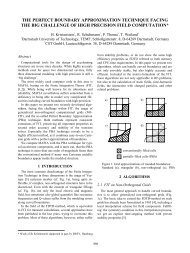
agonal split line (Fig. 1) sealed with an ‘O’ ring. The intent<br />
is to provide a very rigid base <strong>and</strong> heavy back wall on which<br />
to mount <strong>the</strong> turbo pumps, diagnostics, gauges <strong>and</strong> rf coupling<br />
loop; leaving <strong>the</strong> lid a lighter structure easily removable<br />
for access. The diagonal split line provides exceptional<br />
accessibility. Cooling water manifolds run along <strong>the</strong> front<br />
floor <strong>of</strong> <strong>the</strong> tank fed by penetrations in <strong>the</strong> tank floor. The<br />
inside <strong>of</strong> <strong>the</strong> tank is completely cyanide bath copper plated.<br />
This was accomplished by using each half <strong>of</strong> <strong>the</strong> tank as its<br />
own bath vessel – tipped 45 . All <strong>the</strong> mounting pads on <strong>the</strong><br />
floor are machined in one pass to ensure <strong>the</strong>y are co-planar.<br />
The tank base is mounted on a 9 m x 1.5 m x 0.5 m concrete<br />
pad with 22 imbedded studs to match <strong>the</strong> 7 mounting<br />
flanges on <strong>the</strong> tank base. In order to avoid distortion, <strong>the</strong><br />
tank is set down on epoxy grout which is allowed to set before<br />
<strong>the</strong> nuts are torqued. After final adjustment no movement<br />
<strong>of</strong> <strong>the</strong> tank base was observed when <strong>the</strong> lid was bolted<br />
down or when <strong>the</strong> tank was evacuated. Each half <strong>of</strong> <strong>the</strong> tank<br />
has forty-two 500 W heaters uniformly installed, covered<br />
with a glass fiber blanket, for bake out. A tank temperature<br />
<strong>of</strong> 60 C is reached in less than 2 hours creating a longitu-<br />
hinge<br />
rf skin<br />
rf shroud<br />
concrete base<br />
split line<br />
electrodes<br />
Figure 1: End view <strong>of</strong> <strong>RFQ</strong> tank assembly.<br />
electrode<br />
support<br />
strong<br />
back<br />
stem<br />
baseplate<br />
platen<br />
adjusters
dinal growth <strong>of</strong> 2.0 mm. The elasticity <strong>of</strong> <strong>the</strong> mounting<br />
system copes with this <strong>and</strong> growth returns to zero at operating<br />
temperature.<br />
3 ACCELERATOR COMPONENTS<br />
3.1 <strong>Design</strong> Considerations<br />
Each ring is identical <strong>and</strong> consists <strong>of</strong> a base, a stem, a split<br />
strong back, two electrode supports <strong>and</strong> an rf skin (Fig. 1).<br />
To achieve <strong>the</strong>rmal stability all rf surfaces are water cooled<br />
(except for <strong>the</strong> outer rf skin). This is done by using two separate<br />
water circuits. Circuit 1 supplies cooling water from<br />
<strong>the</strong> inlet manifold to a tube array soldered on <strong>the</strong> inside <strong>of</strong><br />
<strong>the</strong> inner rf skin; from <strong>the</strong>re <strong>the</strong> water enters a circuit drilled<br />
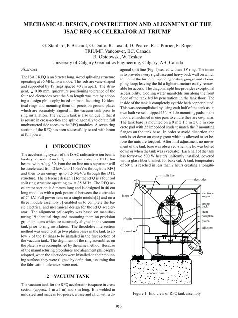
into <strong>the</strong> electrode support (Fig. 2) <strong>and</strong> <strong>the</strong>n returns to <strong>the</strong><br />
outer manifold. Circuit 2 transports water from <strong>the</strong> inlet<br />
manifold to <strong>the</strong> electrode supports through <strong>the</strong> electrodes to<br />
<strong>the</strong> adjacent ring. Hence, with a 3-ring platen, number 2ring<br />
supplies water to <strong>the</strong> 4 electrodes, <strong>and</strong> number 1 <strong>and</strong> 3<br />
rings receive <strong>and</strong> return <strong>the</strong> water. The rf skin encloses <strong>the</strong><br />
strong back but is attached only where it meets <strong>the</strong> electrode<br />
supports, thus allowing for <strong>the</strong>rmal growth <strong>of</strong> <strong>the</strong> skin without<br />
loading <strong>the</strong> structure <strong>and</strong> causing electrode misalignment.<br />
Prototype tests indicate a very small movement during<br />
voltage ramp-up but this returns to zero at steady state.<br />
Tests on <strong>the</strong> seven rings showed no movement at all.<br />
As mentioned <strong>the</strong> philosophy <strong>of</strong> mechanical positioning,<br />
or alignment <strong>of</strong> <strong>the</strong> rings, in order to control <strong>the</strong> accuracy <strong>of</strong><br />
<strong>the</strong> electrodes around a true datum line in space (i.e., beam<br />
centerline), is to make each ring identical such that when<br />
sitting in a jig on its baseplate <strong>the</strong> electrode mounting pads<br />
are within 25 m, <strong>of</strong> true position. In <strong>the</strong> tank <strong>the</strong>re are 6<br />
platens – <strong>the</strong> first supports 4 rings, <strong>and</strong> <strong>the</strong> remaining five 3<br />
rings each. Each platen consists <strong>of</strong> a special steel 63.5 mm<br />
thick with an <strong>of</strong>fset longitudinal rail bolted <strong>and</strong> doweled in<br />
place. The platen <strong>and</strong> rail are accurately ground in one set<br />
up, thus providing accurate datums for mounting <strong>and</strong> locating<br />
<strong>the</strong> ring bases (<strong>the</strong> flatness tolerances, i.e., 12 m).<br />
The platens have 5 adjustable mounting points - 3 vertical<br />
Figure 2: Electrode support showing holes drilled for water<br />
cooling circuits.<br />
981<br />
<strong>and</strong> 2 lateral. Each platen is adjusted in <strong>the</strong> tank using special<br />
targets for each platen <strong>and</strong> aligned by <strong>the</strong> <strong>the</strong>odolite<br />
intersection procedure which is covered in a later section.<br />
Once <strong>the</strong> platens are aligned <strong>the</strong>y are locked in position <strong>and</strong><br />
are ready for installation <strong>of</strong> <strong>the</strong> rings.<br />
3.2 Fabrication Considerations<br />
In order to achieve <strong>the</strong> manufacture <strong>of</strong> identical rings a<br />
philosophy <strong>of</strong> fabrication <strong>and</strong> assembly had to be decided<br />
upon. The key to this is that <strong>the</strong> mounting surface on which<br />
<strong>the</strong> vane shaped electrodes are mounted are machined as <strong>the</strong><br />
last major operation. In order to achieve this with such an<br />
awkward shape it was decided to use Electrical Discharge<br />
Machining (EDM) <strong>and</strong> employ a master fixture that would<br />
engage datum features on <strong>the</strong> ring base (<strong>the</strong> same features<br />
that would eventually engage <strong>the</strong> datums on <strong>the</strong> platen) <strong>and</strong><br />
accurately hold <strong>the</strong> ring in <strong>the</strong> EDM machine for final machining,<br />
thus ensuring that all rings are machined in an identical<br />
set up. This master fixture also had provision for addition<br />
<strong>of</strong> inspection tooling to check <strong>the</strong> result. The same<br />
fixture was also used to manufacture special targets previously<br />
mentioned which are used to align <strong>the</strong> platens. Finally,<br />
each ring is inspected by an independent organization<br />
using a coordinate measuring system. This method <strong>of</strong> ring<br />
manufacture means that individual components can be held<br />
to reasonable tolerances with enough machine allowance on<br />
<strong>the</strong> electrode platform to accommodate <strong>the</strong> accumulated assembly<br />
tolerances. Prior to EDM machining at final assembly,<br />
all components are doweled toge<strong>the</strong>r <strong>and</strong> cleaned.<br />
The electrode support is also <strong>of</strong> some complexity due to<br />
<strong>the</strong> cooling circuits drilled within <strong>the</strong> shape <strong>of</strong> this component<br />
(see Fig. 2). This is a fully NC machined component<br />
produced to a better than 0.80 m surface finish in<br />
chromium copper (tellurium copper was chosen due to a<br />
higher machinability <strong>and</strong> conductivity rating but pieces <strong>of</strong><br />
this size are unavailable).<br />
The only o<strong>the</strong>r components that require special mention<br />
are <strong>the</strong> electrodes <strong>and</strong> <strong>the</strong> rf skin. The electrodes are <br />
13 mm x 38 mm x 120 cm long (except <strong>the</strong> first two sets<br />
which are 80 cm long) <strong>and</strong> made from tellurium copper for<br />
improved machinability <strong>and</strong> good conductivity. The rods<br />
are rough machined, gun drilled for water cooling channels<br />
<strong>and</strong> straightened by <strong>the</strong> supplier. The cooling holes are<br />
plugged at ei<strong>the</strong>r end with silver soldered plugs. They are<br />
<strong>the</strong>n finally machined <strong>and</strong> pr<strong>of</strong>ile cut on an NC machine to<br />
an overall tolerance <strong>of</strong> 25 m. Both <strong>the</strong> electrode <strong>and</strong><br />
electrode support quality <strong>and</strong> accuracy met or exceeded our<br />
expectations.<br />
The rf skin is made from 2.2 mm thick C110 copper <strong>and</strong><br />
<strong>the</strong> u-shaped ring was created by spinning over a m<strong>and</strong>rel<br />
in two pieces that were later brazed toge<strong>the</strong>r. Mounting<br />
frames <strong>and</strong> flanges are soldered <strong>and</strong> finished machined <strong>and</strong><br />
<strong>the</strong> cooling array is <strong>the</strong>n soldered in position.
3.3 Assembly<br />
Rings were assembled in a semi-clean room environment.<br />
The base, stem <strong>and</strong> strong back <strong>and</strong> electrode supports were<br />
bolted toge<strong>the</strong>r <strong>and</strong> aligned in a fixture. These components<br />
were <strong>the</strong>n drilled <strong>and</strong> reamed to allow repeatability during<br />
<strong>the</strong> cleaning <strong>and</strong> subsequent disassembly in order to fit <strong>the</strong><br />
rf skin. Once <strong>the</strong> ring was completely assembled it was<br />
shipped to <strong>the</strong> EDM shop in a special protective container.<br />
H<strong>and</strong>ling was a major issue due to <strong>the</strong> awkward shape, high<br />
centre <strong>of</strong> gravity, <strong>and</strong> fragility <strong>of</strong> <strong>the</strong> rings, hence several<br />
h<strong>and</strong>ling devices were employed to avoid accidents.<br />
After final EDM machining <strong>and</strong> inspection <strong>the</strong> rings were<br />
cleaned <strong>and</strong> installed onto <strong>the</strong> previously aligned platens<br />
<strong>and</strong> <strong>the</strong> accuracy <strong>of</strong> <strong>the</strong>ir placement in situ was measured,<br />
<strong>the</strong> results <strong>of</strong> which are discussed in <strong>the</strong> next section.<br />
4 ALIGNMENT OF PLATENS AND<br />
RINGS<br />
<strong>Alignment</strong> <strong>of</strong> <strong>the</strong> first 2 platens was done as a two step<br />
process involving a direct on beam axis sighting with an<br />
alignment telescope to position <strong>the</strong> platens, <strong>and</strong> confirmation<br />
<strong>of</strong> <strong>the</strong> position using a three dimensional <strong>the</strong>odolite intersection<br />
technique. Four alignment monuments with targets<br />
on <strong>the</strong> beam axis for direct position <strong>and</strong> <strong>of</strong>f <strong>the</strong> beam<br />
axis to eliminate rotation about <strong>the</strong> beam axis were manufactured<br />
in <strong>the</strong> ring assembly jig using EDM. These monuments<br />
which simulated <strong>the</strong> rings were placed on <strong>the</strong> upstream<br />
<strong>and</strong> downstream ends <strong>of</strong> both platens. The platens<br />
were <strong>the</strong>n adjusted so that <strong>the</strong> monument targets were on<br />
beam axis defined by a line <strong>of</strong> sight telescope with a resolving<br />
power <strong>of</strong> 3.4 arc sec (0.08 mm) <strong>and</strong> <strong>of</strong>fset micrometer<br />
resolution <strong>of</strong> 0.001”.<br />
The three dimensional <strong>the</strong>odolite technique involves locating<br />
two <strong>the</strong>odolites within a known grid <strong>the</strong>n measuring<br />
<strong>the</strong> angles to monument targets to compute <strong>the</strong>ir coordinates.<br />
Two 1 sec electronic <strong>the</strong>odolites (KERN E2)<br />
<strong>and</strong> <strong>the</strong>ir in-house s<strong>of</strong>tware, SIMS (SLAC industrial measurements<br />
system), were used to process <strong>the</strong> data. Simulations<br />
using a grid <strong>of</strong> five fixed points <strong>and</strong> two independent<br />
measurements <strong>of</strong> <strong>the</strong> targets with both <strong>the</strong>odolites indicated<br />
measurement accuracy <strong>of</strong> 0.04 mm in <strong>the</strong> vertical <strong>of</strong>f axis<br />
<strong>and</strong> on beam axis directions <strong>and</strong> 0.075 mm in <strong>the</strong> horizontal<br />
<strong>of</strong>f axis direction. Physical constraints that required <strong>the</strong><br />
<strong>the</strong>odolites<strong>and</strong> <strong>the</strong> grid to be onlyalong one side <strong>of</strong> <strong>the</strong> <strong>RFQ</strong><br />
meant that <strong>the</strong> horizontal <strong>of</strong>f axis measurement are less accurate<br />
because <strong>the</strong>y are along <strong>the</strong> <strong>the</strong>odolite sight line.<br />
The grid was established by measuring angles to 17<br />
points with both <strong>the</strong>odolites <strong>and</strong> <strong>the</strong> distance between two<br />
<strong>of</strong> <strong>the</strong> points which was defined by an invar scale with a tolerance<br />
<strong>of</strong> 0.013 mm. All measurements were done twice<br />
to improve <strong>the</strong> accuracy. Five points in <strong>the</strong> concrete base<br />
beneath <strong>the</strong> <strong>RFQ</strong> were used to establish <strong>the</strong> fixed points<br />
for <strong>the</strong> grid. The alignment <strong>of</strong> <strong>the</strong> platens was <strong>the</strong>n confirmed<br />
by <strong>the</strong>odolite intersection <strong>of</strong> <strong>the</strong> alignment monuments<br />
to be on a straight line within 0.010 0.025 mm<br />
982<br />
vertically <strong>and</strong> within 0.080 0.100 mm horizontally. Following<br />
this measurement <strong>the</strong> seven rings were installed on<br />
<strong>the</strong> platens <strong>and</strong> a datum face on one side <strong>of</strong> each ring was<br />
measured with <strong>the</strong> <strong>the</strong>odolites. The relative aligment <strong>of</strong> <strong>the</strong><br />
rings shown in Fig. 3 shows that <strong>the</strong> rings were aligned to<br />
a straight line within 0.060 0.045 mm horizontally <strong>and</strong><br />
0.040 0.010 mm vertically which is well within <strong>the</strong> strident<br />
alignment requirement <strong>of</strong> 0.080 mm. The remaining<br />
12 rings will be aligned by extending <strong>the</strong> grid to <strong>the</strong> adjacent<br />
platen to be aligned <strong>and</strong> <strong>the</strong>n aligning <strong>the</strong> platen to <strong>the</strong><br />
line defined by <strong>the</strong> previously aligned platens. This process<br />
will be repeated as <strong>the</strong> grid is extended to <strong>the</strong> next platen to<br />
be aligned. Each platen will be aligned to <strong>the</strong> new straight<br />
line.<br />
Figure 3: Relative alignment <strong>of</strong> <strong>RFQ</strong> rings.<br />
5 CONCLUSION<br />
The outst<strong>and</strong>ingresults obtained with beam at full power[4]<br />
is a positive indication that <strong>the</strong> mechanical design, construction<br />
<strong>and</strong> alignment philosophy adopted was a success.<br />
6 ACKNOWLEDGEMENT<br />
A special thanks to Bhalwinder Warich, Peter Harmer <strong>and</strong><br />
Tim Emmens for <strong>the</strong> assembly <strong>and</strong> installation <strong>of</strong> <strong>the</strong> <strong>RFQ</strong><br />
components, <strong>and</strong> <strong>the</strong> beam line/alignment group for <strong>the</strong>ir<br />
help in <strong>the</strong> alignment <strong>of</strong> <strong>the</strong> tank, platens <strong>and</strong> rings. TRI-<br />
UMF would also like to thank <strong>the</strong> alignment group at SLAC<br />
for <strong>the</strong> loan <strong>of</strong> <strong>the</strong> two <strong>the</strong>odilites <strong>and</strong> <strong>the</strong>ir in-house s<strong>of</strong>tware.<br />
7 REFERENCES<br />
[1] P.G. Bricault <strong>and</strong> H.R. Schneider, “Simulation <strong>of</strong> <strong>the</strong> TRI-<br />
UMF Split Ring 4-Rod <strong>RFQ</strong> with MAFIA”, Proc. 1995 Particle<br />
Accelerator Conf. <strong>and</strong> Int. Conf. on High-Energy Accelerators,<br />
1125 (1995).<br />
[2] R.L. Poirier, P.J. Bricault, K. Jensen <strong>and</strong> A.K. Mitra, “The<br />
<strong>RFQ</strong> Prototype for <strong>the</strong> Radioactive Ion Beams Facility at TRI-<br />
UMF”, Proc. XVIII LINAC Conference, CERN, 405 (1996).<br />
[3] R.L. Poirier, P. Bricault, G. Dutto, K. Fong, K. Jensen,R. Laxdal,<br />
A.K. Mitra, <strong>and</strong> G. Stanford, “<strong>Construction</strong> Criteria <strong>and</strong><br />
Prototyping for <strong>the</strong> <strong>ISAC</strong> <strong>RFQ</strong> Accelerator at TRIUMF”,<br />
Proc. 1997 Particle Accelerator Conference.<br />
[4] R. Laxdal, “First Beam Tests with <strong>the</strong> <strong>ISAC</strong> <strong>RFQ</strong>”, this conference.