The Monolithic Two Axis Flexure Joined Mirror Support - Advanced ...
The Monolithic Two Axis Flexure Joined Mirror Support - Advanced ...
The Monolithic Two Axis Flexure Joined Mirror Support - Advanced ...

Create successful ePaper yourself
Turn your PDF publications into a flip-book with our unique Google optimized e-Paper software.
2 nd International Workshop on Mechanical Engineering Design of Synchrotron Radiation Equipment and Instrumentation (MEDSI02)<br />
September 5-6, 2002 – <strong>Advanced</strong> Photon Source, Argonne National Laboratory, Argonne, Illinois U.S.A.<br />
<strong>The</strong> <strong>Monolithic</strong> <strong>Two</strong> <strong>Axis</strong> <strong>Flexure</strong> <strong>Joined</strong> <strong>Mirror</strong> <strong>Support</strong> and<br />
the Mechanical Design of the Infrared Beamline<br />
T. Noll, C. Kalus, W. B. Peatman, U. Schade, and W. v. Scheibner<br />
Abstract<br />
BESSY GmbH, Albert-Einstein-Strasse 15, D-12489 Berlin-Adlershof<br />
Phone: + 49 - (30)6392 4655; Fax: + 49 - (30)6392 2990<br />
E-mail: noll@bessy.de<br />
At the electron storage ring BESSY a new and innovative infrared beamline has been designed<br />
and built for experiments in biology, biophysics and material science. In order to fulfill the<br />
stringent stability requirements a basically new mirror moving mechanism had to be developed.<br />
This unit is based on a monolithic body which contains two independent segments of rotational<br />
symmetric flexure hinge patterns [1-3]. <strong>The</strong> design provides two rotational axes which intersect<br />
the midpoint of the mirror surface normal to each other and parallel to the mirror surface. <strong>The</strong><br />
flexure hinge patterns interpenetrate in two orthogonal directions. <strong>The</strong> monolithic body<br />
additionally includes the elastically loaded kinematic mirror mount. Its motion is driven by two<br />
linear feedthroughs.<br />
Advantages over classical mirror moving mechanisms are: it requires only little space, works<br />
very smoothly, producing a high positioning accuracy and is vibrationally stiff. Because of the<br />
monolithic design the UHV compatibility is good.<br />
Keywords: mirror support, weak link mechanism<br />
1. <strong>The</strong> Infrared Beamline: Layout and Configuration<br />
<strong>The</strong> new infrared beamline at BESSY was successfully commissioned in the first<br />
half of 2002 and has since been turned over to user operation [4]. <strong>The</strong> first part of the<br />
beamline is located in the tunnel of the storage ring and the second part on the top of the<br />
storage ring tunnel (Figure 1). <strong>The</strong> related experimental place is also on the concrete<br />
tunnel whose thickness is 0.7 m. <strong>The</strong> first part of the IR- beamline consists of two vertical<br />
optical columns and the transverse section between the columns. <strong>The</strong> first mirror is<br />
located at the bottom of the first column in the dipole chamber. It is vertically movable to<br />
three positions. <strong>The</strong> manual valve between the dipole chamber and the first column can<br />
be closed if the mirror is in the upper position. In the mid position the mirror is out of the<br />
electron storage ring plane and is not thermally loaded from the high energy fan of the<br />
synchrotron radiation. In the lower position the mirror is supported in a conical base<br />
inside the dipole vacuum chamber. It can be aligned in a small range by tipping the lift<br />
rod on the top of the vacuum column. <strong>The</strong> mirror reflects the infrared light vertically out<br />
of the ring plane [5]. <strong>The</strong> mirror was subdivided in two segments to pass the high energy<br />
radiation through to an absorber. To ensure the coincidence of the surfaces of both mirror<br />
segments their edges are pressed onto a planar lapped frame which also gives sufficient<br />
thermal contact. <strong>The</strong> mirror support and the mirror itself are made of OFHC-copper. <strong>The</strong><br />
former is water cooled. <strong>The</strong> outside surface of the mirror support was rhodium coated to<br />
harden it and to reduce friction and abrasion.<br />
65
2 nd International Workshop on Mechanical Engineering Design of Synchrotron Radiation Equipment and Instrumentation (MEDSI02)<br />
September 5-6, 2002 – <strong>Advanced</strong> Photon Source, Argonne National Laboratory, Argonne, Illinois U.S.A.<br />
<strong>The</strong> second mirror is located in the upper part of the first column. It has a<br />
cylindrical surface to focus the light sagittally just in front of the diamond window above<br />
the tunnel ceiling. It reflects the light horizontally through the transverse section to the<br />
third mirror, which focuses the light meridonally at the same point.<br />
infrared microscope<br />
tunnel ceiling of 0,7 meter thickness<br />
two hexapodes to hang the mirror<br />
units rigide to the concret ceiling<br />
columne 2<br />
electron beam of<br />
the storage ring<br />
vibrational isolated transverse<br />
unit with ion getter pumps<br />
spectrometer<br />
dipole vacuum chamber<br />
Fig. 1: <strong>The</strong> infrared beamline, overall view.<br />
leaf spring plate for<br />
a vertical elastic and<br />
lateral stiff connection<br />
to the concret ceiling<br />
columne 1<br />
In total, the infrared system contains eight mirrors. <strong>The</strong> remaining five are in the<br />
second part of the system on top of the tunnel. An important characteristic of an infrared<br />
beamline is its vibrational behavior. <strong>The</strong> typical experiments are extremely sensitive to<br />
vibrations. Hence, the mirrors may not vibrate in the range of 2 Hz - 2 KHz. <strong>The</strong> columns<br />
which are the mirror chambers were mounted on the concrete ceiling with W-type<br />
hexapods. Because of the thickness and monolithic character of the concrete tunnel it is a<br />
suitable base for that beamline.<br />
66
2 nd International Workshop on Mechanical Engineering Design of Synchrotron Radiation Equipment and Instrumentation (MEDSI02)<br />
September 5-6, 2002 – <strong>Advanced</strong> Photon Source, Argonne National Laboratory, Argonne, Illinois U.S.A.<br />
<strong>The</strong> transverse unit of the beamline contains two ion getter pumps to ensure the<br />
ultra-high vacuum. A gate valve divides the frontend into two vacuum sections. <strong>The</strong><br />
pumping unit is separated from the mirror vessels by edge welded bellows on each side<br />
and is fixed apart from the optical columns to the ceiling.<br />
<strong>The</strong> two optical columns must remain in fixed optical alignment with respect to<br />
each other and to the source. In order to compensate for thermal expansion, the first<br />
column, which is rigidly connected to the dipole chamber at the lower end, is centered<br />
and the weight carried by an aluminium plate which provides vertical flexure but is very<br />
stiff in the horizontal translational directions. Thus, the aluminium plate supports the<br />
main weight of the system and does not over constrain the vacuum vessel. <strong>The</strong> lower end<br />
of the second column is rigidly mounted by a hexapod to the tunnel ceiling. <strong>The</strong> upper<br />
end is centered by a guide bushing on top of the tunnel to allow free expansion of the<br />
column in vertical direction. A strut system between the optical columns prevents<br />
rotations.<br />
In Figure 2 the W-type hexapods are visible which fix the vacuum vessels to the<br />
ceiling. <strong>The</strong>se hexapods must be aligned only once when the beamline is assembled and<br />
commissioned. To facilitate the difficult alignment procedure software is used to<br />
calculate the changes of each strut in order to move the chamber a specific distance in<br />
Cartesian directions.<br />
adjustable cross supports<br />
vertical leaf spring support plate<br />
transverse section<br />
(not shown here)<br />
Fig. 2: Structure of the first and second column with cross support.<br />
<strong>The</strong> mid-part of the struts of the W-type hexapods are threaded rods which are<br />
fixed at their ends with two nuts to the heavy sheet metal loops. <strong>The</strong>se nuts were also<br />
used to perform the modifications to the strut length. <strong>The</strong> pitch of the thread needs to be<br />
known in order to apply defined movements in a accuracy of tenths of millimeters.<br />
67
2 nd International Workshop on Mechanical Engineering Design of Synchrotron Radiation Equipment and Instrumentation (MEDSI02)<br />
September 5-6, 2002 – <strong>Advanced</strong> Photon Source, Argonne National Laboratory, Argonne, Illinois U.S.A.<br />
<strong>The</strong> cross supports between the columns are necessary because of the use of edge<br />
welded bellows in the cross section. <strong>The</strong> nominal size of 250 mm of the bellows produces<br />
an air pressure caused force of 4909 N. In addition to preventing rotations of the optical<br />
columns the cross struts counter this compression.<br />
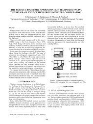
2. Vibration Suspension<br />
<strong>The</strong>re are two possible strategies to passively reduce the amplitudes of vibrations.<br />
It can be worked with large masses when heavy frames are placed on soft damping<br />
mountings. This is the typical method for measuring machines where for example, granite<br />
bodies are used as durable base bed for a precision guide system.<br />
A basically different strategy is to use the massive concrete of the tunnel as a base<br />
for mounting the optical components as stiffly as possible. <strong>The</strong> intention is to reduce the<br />
relative vibrations between the concrete and the mirrors and thus the relative vibrations<br />
between all optical components of the beamline. For this method the maximization of the<br />
stiffness of the support is associated with the minimization of the vibrating mass [6]. That<br />
model becomes clearer through the analytical equation of the first natural frequency. <strong>The</strong><br />
cyclic frequency of a nondamped system is:<br />
2 c<br />
ω = ,<br />
m<br />
while the interrelation between the cyclic frequency and the natural frequency is<br />
ω<br />
f = , where<br />
2π<br />
ω = the cyclic frequency,<br />
m = the vibrating mass,<br />
c = the spring constant of the supporting structure and<br />
f = the first natural frequency.<br />
Following these considerations the vacuum vessel, the frame and the adjustable<br />
mirror mount were optimized in order to reduce their mass and to increase their stiffness.<br />
<strong>The</strong> mirror moving mechanism is based on extensive experience with six strut<br />
arrangements for Cartesian movements [7-9].<br />
3. <strong>The</strong> Movable <strong>Mirror</strong> <strong>Support</strong>s<br />
<strong>The</strong> mirror support consists of a lightweight monolithic aluminium body with<br />
several features. Along with the static support of the mirror and its elastic mount it works<br />
as flexural guidance for two rotations of the mirror. Both rotational axes are parallel to<br />
the surface of the mirror, normal to each other and cross at the midpoint of the mirror<br />
surface.<br />
68
2 nd International Workshop on Mechanical Engineering Design of Synchrotron Radiation Equipment and Instrumentation (MEDSI02)<br />
September 5-6, 2002 – <strong>Advanced</strong> Photon Source, Argonne National Laboratory, Argonne, Illinois U.S.A.<br />
Figure 3 shows the adjustable mirror unit and its rotational axes. Stepper motors<br />
drive linear motion feedthroughs which are connected to the mirror support by struts with<br />
flexure fibre joints at their ends [10,11].<br />
rotational<br />
z-axis<br />
z<br />
y<br />
x<br />
mirror<br />
rotational<br />
x-axis<br />
clamp spring features<br />
driving struts<br />
hold down for the<br />
mirror support<br />
linear motion feedthroughs<br />
Fig. 3: Movable mirror support of the second and third<br />
mirrors of the infrared beamline.<br />
In Fig. 4 the multiple parallel flexure hinge patterns are represented. <strong>The</strong> systems<br />
of each axis interpenetrate in two orthogonal views. <strong>The</strong> figure shows the monolithic<br />
aluminium body without the mirror in two directions. <strong>The</strong> view planes are normal to the<br />
rotational axes to display the mode of action of the strut patterns. <strong>The</strong> thin dashed lines<br />
illustrate the line of action of the single struts and show that the rotational axis of each<br />
motion lies in the intersection of the lines of action.<br />
For the rotation around the z-axis five flexure hinged strut rows are operating in<br />
parallel. <strong>The</strong> rotation around the x-axis is guided by seven rows of flexural hinged struts<br />
which also work in parallel. <strong>The</strong> interpenetration of the weak link arrays produces thirtyfive<br />
single struts where the grooved bending joint zones are located on different positions<br />
along each strut. Thus, the joints are essentially no flexure ball joints. <strong>The</strong> high level of<br />
parallelism leads to a high stiffness and reduces parasitic motions [12].<br />
69
2 nd International Workshop on Mechanical Engineering Design of Synchrotron Radiation Equipment and Instrumentation (MEDSI02)<br />
September 5-6, 2002 – <strong>Advanced</strong> Photon Source, Argonne National Laboratory, Argonne, Illinois U.S.A.<br />
z-axis<br />
dubble rotatable mirror mount<br />
weak link array<br />
for x-rotation<br />
weak link array<br />
for z -rotation<br />
nonmovable base<br />
Fig. 4: <strong>Two</strong> projected views of the flexure mirror support.<br />
<strong>The</strong> length of the struts and the dimensions of their joints were subject of an<br />
optimization in Pro/Mechanica with an enforced displacement of 1° in two axes. <strong>The</strong><br />
maximal von Mises stress in the joints is 144 MPa. <strong>The</strong> modal analysis calculates the first<br />
natural frequency to be 132 Hz. All joints of the flexure hinge patterns are in the elastic<br />
range of the aluminium cast alloy [13] whose ultimate stress is 240 MPa. Thus, there is<br />
no plastic deformation and no hysteresis. Because of the safety factor of 1.66 a high<br />
number of moving cycles is guaranteed until the first fatigue cracks of single joints occur.<br />
Figure 5 shows the exaggerated deformation of a rotation around the x-axis.<br />
Manufacturing by milling and erode processes took place in a specialized workshop [14].<br />
Fig. 5: Deformed pattern of flexure joined struts:<br />
dramatically exaggerated simulation plot of Pro/Mechanica.<br />
70<br />
x-axis
2 nd International Workshop on Mechanical Engineering Design of Synchrotron Radiation Equipment and Instrumentation (MEDSI02)<br />
September 5-6, 2002 – <strong>Advanced</strong> Photon Source, Argonne National Laboratory, Argonne, Illinois U.S.A.<br />
4. <strong>The</strong> <strong>Mirror</strong> Mount<br />
Figure 6 shows the integrated spring clamp for fixing the mirror elastically. On its<br />
backside the mirror lies on three alignment screws with ball contacts. <strong>The</strong> springy ends of<br />
the clamps have coaxial holes in which supporting pieces with a spherical surface are<br />
screwed.<br />
elastic clamping<br />
shanks for definition<br />
in y-direction<br />
elastic shanks<br />
for z- definition<br />
thread hole for<br />
support in<br />
x- direction<br />
elastic shanks<br />
for z- definition<br />
threads for the<br />
support screws<br />
and for the opposing<br />
tips<br />
Fig. 6: <strong>Monolithic</strong> integrated clamp springs for mounting the mirror.<br />
To assemble the mirror the alignment screws must be turned down until they<br />
disappear in the bed. <strong>The</strong> mirror can easily be moved into the t-slot without hitting or<br />
scratching any hindrances. After that the alignment screws are turned out in order to fix<br />
the mirror elastically and pre-align the mirror on its kinematic mount. <strong>The</strong> flexure clamp<br />
shanks are optimized for an elastic deformation of 1.5 mm with a pressure force of 30 N<br />
to assure fixing the Si mirror of a weight of 955 g. <strong>The</strong> t-slot is closed with a leaf spring<br />
(see Fig. 3).<br />
<strong>The</strong> arrangement of the linear motion feedthroughs (Fig. 7) and especially the<br />
strut ends are very important for cartesian movements. <strong>The</strong> turning lever is given by the<br />
distance of the connecting point to the middle of the mirror. <strong>The</strong> lengths of the lever (lx<br />
and lz) influence the load on the feedthrough and the angle increment per linear step of<br />
the drive. <strong>The</strong> rotation around the x-axis has to be arranged so that its extended line of<br />
influence intersects the z- rotational axis. <strong>The</strong> drive for the rotation around the z-axis<br />
needs to be arranged in a way that its line of influence intersects the x-rotational axis. <strong>The</strong><br />
closer the connecting points come to the axis the smaller is the motion deviation.<br />
71
2 nd International Workshop on Mechanical Engineering Design of Synchrotron Radiation Equipment and Instrumentation (MEDSI02)<br />
September 5-6, 2002 – <strong>Advanced</strong> Photon Source, Argonne National Laboratory, Argonne, Illinois U.S.A.<br />
5. Conclusions<br />
point of intersection<br />
z-rotational axis<br />
strut axis for x-drive<br />
l x<br />
z<br />
y<br />
l z<br />
x<br />
x-rotational axis<br />
point of intersection<br />
strut axis for z-drive<br />
Fig. 7: <strong>Mirror</strong> support with driving struts; the line of<br />
influence of each strut needs to intersect the opposite axis<br />
of rotation.<br />
For vibration sensitive infrared experiments at the electron storage ring BESSY a<br />
beamline with new features has been developed and is presently starting user operation.<br />
<strong>The</strong> reduction of the mass of the components leads to an extremely stiff installation with<br />
very small vibration amplitudes and high natural frequencies. An innovative mirror<br />
support with two flexure joined rotational axis and integrated features to elastically clamp<br />
the mirror has been developed.<br />
6. References<br />
[1] D. Shu, “Ultraprecision Motion Control Technique for High-Resolution X-Ray<br />
Instrumentation,” Proceedings of the 1st International Workshop on Mechanical<br />
Engineering Design of Synchrotron Radiation Equipment and Instrumentation,<br />
Paul Scherrer Institute Villingen, Switzerland, July 2000.<br />
[2] S. T. Smith, “<strong>Flexure</strong>s, Elements of Elastic Mechanisms,” Gordon and Breach<br />
Science Publishers 2000.<br />
[3] S. T. Smith, D. G. Chetwynd, “Foundations of Ultraprecision Mechanism<br />
Design,” Gordon and Breach Science Publishers 1992.<br />
[4] U. Schade, A. Röser, E. H. Korte, F. Bartl, K. P. Hofmann, T. Noll, W. B.<br />
Peatman: “New infrared spectroscopy beamline at BESSY II,” Rev. Sci. Instrum.<br />
American Institute of Physics 2002.<br />
[5] W. B. Peatman, U. Schade: “A brilliant infrared light source at BESSY,” Rev.<br />
Sci. Instrum. American Institute of Physics 2001.<br />
[6] D. Holzweissig; “Lehrbuch der Maschinendynamik,” Fachbuchverlag Leipzig<br />
1982, p. 135.<br />
72
2 nd International Workshop on Mechanical Engineering Design of Synchrotron Radiation Equipment and Instrumentation (MEDSI02)<br />
September 5-6, 2002 – <strong>Advanced</strong> Photon Source, Argonne National Laboratory, Argonne, Illinois U.S.A.<br />
[7] T. Noll, “<strong>The</strong> Switching <strong>Mirror</strong> Unit for ID-Beamlines,” Contribution to the<br />
MEDSI-2000 Workshop at the Swiss Light Source in Villingen/ Switzerland; July<br />
2000.<br />
[8] T. Noll, Th. Zeschke, G. Reichardt, H. Lammert, W. Gudat, “Six Strut<br />
Arrangements for Cartesian Movements of <strong>Mirror</strong>s,” Poster auf der SRI 2000 (7 th<br />
International Conference on Synchrotron Radiation Instrumentation Berlin) und<br />
Text in den Proceedings in Nuclear Instruments and Methods in Physics<br />
Research, A, Elsevier Science B. V., p. 775).<br />
[9] Patent DE 100 42 802.5 “Vorrichtung zur mehrachsig feinjustierbaren Lagerung<br />
eines Bauteils,” (Tino Noll, Heiner Lammert, Wolfgang Gudat) 20.8.2000.<br />
[10] Registered Design DE 100 42 801.0, “Flexibles Gelenk hoher axialer Steifigkeit,”<br />
BESSY (Tino Noll, Wolfgang Gudat) 2000.<br />
[11] T. Noll, “<strong>Flexure</strong> Joints of High Axial Stiffness,” Precision Engineering Elsevier<br />
Science B. V. 5298, (2002) p. 1-6.<br />
[12] S. Zelenika, “Parasitic Motion of Cross-Spring Pivots: <strong>The</strong>oretical Analysis and<br />
Experimental Assessment,” Proceedings of the 1st International Workshop on<br />
Mechanical Engineering Design of Synchrotron Radiation Equipment and<br />
Instrumentation, Paul Scherrer Institute Villingen, Switzerland, July 2000.<br />
[13] Aluminium alloy ACP 5080 of ALIMEX GmbH.<br />
[14] Budik Werkzeug und Formenbau GmbH, Breitenfelde, Germany.<br />
73