SD-57 - Sporlan Online
SD-57 - Sporlan Online
SD-57 - Sporlan Online

You also want an ePaper? Increase the reach of your titles
YUMPU automatically turns print PDFs into web optimized ePapers that Google loves.
INSTALLATION & SERVICE INSTRUCTIONS<br />
®<br />
DISCHARGE BYPASS VALVES<br />
ADRI(E)-11/4, ADRS(E)-2, DRS(E)-2, ADRP(E)-3, DRP(E)-3, ADRH(E)-6, DRH(E)-6<br />
To insure proper performance, discharge bypass valves<br />
must be selected and applied correctly. However, proper<br />
installation procedures are equally as important. Complete<br />
selection and application information on the adjustable models<br />
are covered in Bulletin 90-40. For this type of information on<br />
non-adjustable models, contact your <strong>Sporlan</strong> Representative.<br />
VALVE LOCATION - <strong>Sporlan</strong> discharge bypass valves<br />
(DBV) can be installed in horizontal or vertical lines,<br />
whichever best suits the application and permits easy<br />
accessibility of the valves. However, consideration should be<br />
given to locating these valves so they do not act as oil traps<br />
or so that solder cannot run into the internal parts during<br />
brazing.<br />
The discharge bypass valve should always be installed at<br />
the compressor unit rather than at the evaporator section.<br />
Not only will this insure the rated bypass capacity of the<br />
discharge bypass valve but it will eliminate the possibility<br />
of hot gas condensing in the bypass line (especially on<br />
remote systems). In all cases it is important that some<br />
precautions be taken in mounting the valves. While the<br />
heaviest valve only weighs 3-1/2 pounds, it is suggested<br />
that it be adequately supported to prevent excessive stress<br />
on the connections. See the PIPING section for additional<br />
piping suggestions.<br />
When externally equalized valves are used, the equalizer<br />
connection must be connected to the suction line where it<br />
will sense the desired operating pressure.<br />
If the remote bulb type bypass valve is used, the bulb must<br />
be located in a fairly constant ambient temperature<br />
because the element-bulb assembly is air charged. Since<br />
these valves are set at the factory in an 80°F ambient<br />
temperature, any appreciable variation from this temperature<br />
will cause the pressure setting to vary from the factory<br />
setting. For a non-adjustable valve the remote bulb may be<br />
located in an ambient of 80°F ± 10°F while the adjustable<br />
remote bulb model can be adjusted to operate in a temperature<br />
of 80°F ± 30°F. On many units the manufacturer will<br />
have altered the pressure setting to compensate for an<br />
ambient temperature appreciably different than 80°F.<br />
Therefore on some units, it may be necessary to consult<br />
with the equipment manufacturer for the proper opening<br />
pressure setting of the bypass valve.<br />
There are numerous places on a system where the remote<br />
bulb can be located. Two possible locations are the return<br />
air stream and a structural member of the unit if it is<br />
located in a conditioned space. Other locations, where the<br />
temperature is fairly constant but different than 80°F, are<br />
also available. These include the return water line on a<br />
chiller, the compressor suction line, or the main liquid line.<br />
As mentioned above, the pressure setting may be altered to<br />
compensate for the ambient temperature of the remote bulb.<br />
A bulb strap with bolts and nuts is supplied with each<br />
remote bulb type DBV to use in fastening the bulb in place.<br />
PIPING - <strong>Sporlan</strong> recommends that recognized piping references,<br />
such as equipment manufacturers’ literature and<br />
the ASHRAE Handbook, be consulted for assistance with<br />
proper piping procedures. <strong>Sporlan</strong> is not responsible for<br />
system design, any damage arising from faulty system<br />
design, or for misapplication of its products. If these valves<br />
are applied in any manner other than as described in this<br />
bulletin, Bulletin 90-40, and other <strong>Sporlan</strong> product literature,<br />
the <strong>Sporlan</strong> warranty is void.<br />
Actual system piping must be done so as to protect the<br />
compressor at all times. This includes protection against<br />
over-heating, slugging with liquid refrigerant, and trapping<br />
of oil in various system locations. A few piping guidelines<br />
plus some other installation details are given below for the<br />
various components involved.<br />
Piping Guidelines - Since the DBV is applied in a bypass<br />
line between the discharge line and the low side of a<br />
system, the valve may be subjected to compressor vibrations<br />
which result from discharge gas pulses and inertia<br />
forces associated with the moving parts. Pulsations are best<br />
handled by a good muffler placed as close to the compressor<br />
as possible. Vibrations from the moving parts of the<br />
compressor are best isolated by flexible loops or coils<br />
(discharge lines 1/2" or smaller), or flexible metal hoses for<br />
larger lines. For best results, the hoses should be installed<br />
as close to the compressor as possible, and mounted horizontal<br />
and parallel to the crankshaft or vertically upwards.<br />
The hoses should never be mounted horizontal and 90°<br />
from the crankshaft. A rigid brace should be placed on the<br />
outlet end of the hose to prevent vibrations beyond the hose.<br />
Discharge Bypass Valve - Most piping instructions for<br />
DBV’s are covered in the section VALVE LOCATION.<br />
However, some suggestions are given here to cover piping<br />
the DBV with other pressure regulating valves that may be<br />
used on a system for other purposes.<br />
If a DBV is applied on a system with an evaporator pressure<br />
regulating valve (ORIT or other type), the DBV may<br />
bypass either into the evaporator inlet or the suction line<br />
depending on the specific system. The function of each<br />
valve and the best piping method to adequately protect the<br />
compressor should be the deciding factors.<br />
If the DBV is required on a system with a crankcase pressure<br />
regulating valve (CRO or other type), the bypass valve<br />
can bypass to the low side at the evaporator inlet or the<br />
suction line without difficulties. The only decision necessary<br />
is whether an internally or externally equalized valve<br />
is required and this depends on where the hot gas enters<br />
the low side. The pressure setting of the DBV must be lower<br />
than the CRO setting for each valve to function properly.<br />
Hot Gas Solenoid Valve - If a solenoid valve is applied with<br />
FOR USE ON REFRIGERATION and/or AIR CONDITIONING SYSTEMS ONLY<br />
©COPYRIGHT 2003 BY SPORLAN VALVE COMPANY, WASHINGTON, MO 63090
Page 2<br />
the DBV, it should be located upstream of the bypass valve.<br />
If the solenoid valve is installed downstream of the DBV, the<br />
possibility of trapping oil and/or liquid refrigerant between the<br />
two valves exists. And depending on the ambient temperatures<br />
surrounding the valves and piping, this could be dangerous.<br />
If the hot gas solenoid valve is required for pump down<br />
control, it should be wired in parallel with the liquid line<br />
solenoid valve(s) so they are de-energized by a thermostat<br />
or any of the compressor safety devices.<br />
If the hot gas solenoid valve is used for protection against<br />
high superheat conditions because the compressor does not<br />
have an integral temperature protection device, the solenoid<br />
valve is wired in series with a bi-metal thermostat<br />
fastened to the discharge line close to the compressor.<br />
Additional installation instructions are packed with each<br />
solenoid valve.<br />
Desuperheating Thermostatic Expansion Valve - When the<br />
desuperheating TEV is used in conjunction with the bypass<br />
valve, piping the two valves to get good mixing before<br />
reaching the TEV bulb location is vital. This can be accomplished<br />
several ways but the simplest is to tee the liquidvapor<br />
mixture from the TEV and the hot gas from the DBV<br />
together before connecting a common line to the suction<br />
line. The thermostatic bulb of the TEV should be located<br />
downstream of this common suction connection as near to<br />
the compressor as possible.<br />
When an externally equalized TEV is used, the equalizer<br />
line should be connected to the suction line between the<br />
bulb and the compressor.<br />
Depending on whether pump down control is necessary on the<br />
system and if it is, where the main liquid line solenoid valve is<br />
located, a small solenoid valve may be necessary in the desuperheating<br />
TEV liquid line, ahead of the expansion valve.<br />
This solenoid valve should be wired in parallel with the hot<br />
gas solenoid valve and the other liquid line solenoid valve(s).<br />
Refrigerant Distributor with Auxiliary Side Connection or<br />
Auxiliary Side Connector - When hot gas is bypassed to the<br />
evaporator inlet for capacity control, two piping methods<br />
are available: bypass to the 1650R series distributor’s side<br />
connection or to the auxiliary side connection of the ASC<br />
series connector. Complete application data on these devices<br />
is given in Bulletin 90-40. The major concern in piping either<br />
component is that the piping does not form a trap between the<br />
bypass valve and the side connection. For example when the<br />
distributor or ASC is installed in a horizontal position, the<br />
side connection should be located on top to prevent trapping.<br />
When installing an ASC connector, the nozzle must be<br />
removed from the standard distributor and inserted in the<br />
ASC. This places the nozzle in its proper location upstream<br />
of the hot gas bypass connection.<br />
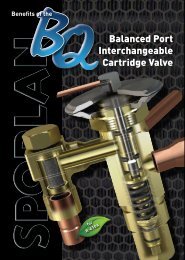
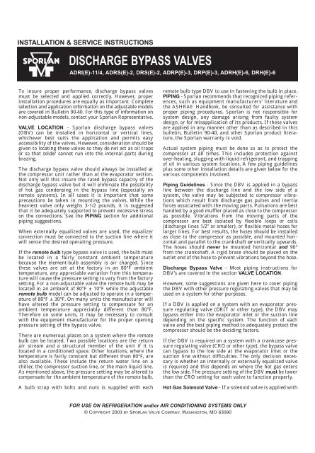
STRAINER - CATCH-ALL FILTER-DRIER - SEE•ALL<br />
MOISTURE and LIQUID INDICATOR - Just as with any<br />
refrigerant flow control device, the need for an inlet<br />
strainer is a function of system cleanliness and proper<br />
installation procedures. When the strainer is used, the<br />
tubing is inserted in the valve connection until the tubing<br />
and the strainer flange ring are up against the tubing stop,<br />
thus locking the strainer in place. See Figure 1. Moisture<br />
and particles too small for the inlet strainer are harmful to<br />
the system and must be removed. Therefore, it is recommended<br />
that a Catch-All Filter-Drier be installed according<br />
to the application recommendations in Bulletin 40-10.<br />
Further system protection is easily and inexpensively<br />
provided with the installation of a See•All Moisture and<br />
Liquid Indicator on every system. Complete information is<br />
ADRH(E)-6<br />
and<br />
DRH(E)-6<br />
MODELS<br />
ALL<br />
OTHER<br />
MODELS<br />
figure 1<br />
given in Bulletin 70-10.<br />
Tubing<br />
Valve<br />
Connection<br />
Tubing Stop<br />
Tubing Stop<br />
Strainer<br />
Valve<br />
Connection<br />
Strainer<br />
Tubing<br />
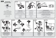
BRAZING PROCEDURES - Any of the commonly used<br />
brazing alloys for high side usage are satisfactory. However,<br />
when soldering or brazing, it is very important that the<br />
internal parts be protected by wrapping the valve with a<br />
WET cloth to keep the body temperature below 300°F. While<br />
the ADRI(E)-1-1/4, ADRS(E)-2, DRS(E)-2, ADRP(E)-3, and<br />
DRP(E)-3 models have metal-to-metal seating material,<br />
the ADRH(E)-6 and DRH(E)-6 valves use synthetic-tometal<br />
seating material and must be protected from overheating.<br />
The extended fittings on the latter models will<br />
adequately protect the synthetic material under normal<br />
conditions. However, when using high temperature solders,<br />
the torch tip should be large enough to avoid prolonged<br />
heating of the copper connections. Always direct the flame<br />
away from the valve body.<br />
TEST and OPERATING PROCEDURES - Inert dry gases<br />
such as nitrogen, CO 2 or helium are often used for leak<br />
detection. Excessive leak testing or operating pressures<br />
may damage these valves and reduce the life of the operating<br />
components. Since a high side test pressure differential<br />
of approximately 350 psig or higher will force the DBV<br />
valve open, the maximum allowable test pressures for our<br />
DBV valves are the same for the high and the low side of<br />
the system. If greater high side test pressures than the<br />
values given in the table below are to be used, some method<br />
must be used to isolate the DBV valve from these high pressures.<br />
CAUTION: Inert gases must be added to the system carefully<br />
through a pressure regulator. Unregulated gas pressure<br />
can seriously damage the system and endanger<br />
human life. Never use oxygen or explosive gases.<br />
The table below lists the maximum values each valve can<br />
withstand without damage. Precautions must be taken to<br />
keep test or operating pressures below these values.<br />
VALVE<br />
TYPE<br />
ADRI(<br />
E)<br />
-1-1/<br />
4<br />
DRS(<br />
E)<br />
-2<br />
ADRS(<br />
E)<br />
-2<br />
DRP(<br />
E)<br />
-3<br />
ADRP(<br />
E)<br />
-3<br />
DRH(<br />
E)<br />
-6<br />
ADRH(<br />
E)<br />
-6<br />
MAXIMUM<br />
ALLOWABLE<br />
PRESSURE<br />
- psig<br />
450<br />
425<br />
425<br />
VALVE SETTING and ADJUSTMENT - A complete discussion<br />
on valve settings is given in the Application Section of<br />
Bulletin 90-40. To determine the proper setting for a<br />
specific system, that section should be reviewed. For application<br />
information on non-adjustable discharge bypass<br />
valves, contact your <strong>Sporlan</strong> Representative.<br />
See the following table for standard factory settings and the<br />
average psi change in setting per one turn of adjustment.
VALVE<br />
ADRI(<br />
E)<br />
ADRS(<br />
E)<br />
-2<br />
ADRP(<br />
E)<br />
-3<br />
ADRH(<br />
E)<br />
-6<br />
ADJ<br />
VALVE<br />
DRH(<br />
E)<br />
-6<br />
ADJUSTABLE<br />
MODELS<br />
ADJUSTMENT<br />
RANGE<br />
STANDARD<br />
SETTING<br />
AVERAGE<br />
psi<br />
CHANGE<br />
PER<br />
TURN<br />
0/ 55<br />
28 9<br />
0/ 75<br />
38 13.<br />
5<br />
0/ 100<br />
50 16<br />
0/ 30<br />
20 3<br />
0/ 80<br />
60 7.<br />
5<br />
USTABLE<br />
REMOTE<br />
BULB<br />
TYPE<br />
( AR<br />
MODELS)<br />
ON<br />
AIR<br />
CONDITIONING<br />
SYSTEMS<br />
ADJUSTMENT<br />
STANDARD<br />
AVERAGE<br />
RANGE<br />
SETTING*<br />
CHANG<br />
PER<br />
TUR<br />
Non-Adjustable Dome<br />
Type Element 4<br />
STANDARD PRESSURE SETTINGS<br />
AVERAGE psi CHANGE PER TURN<br />
25/ 35<br />
30 0.<br />
5<br />
32/ 44<br />
38 0.<br />
75<br />
55/ 70<br />
60 1<br />
65/ 80<br />
70 1<br />
VALVE<br />
TYPE<br />
PART<br />
NUMBER<br />
PART<br />
DESCRIPTION<br />
( A)<br />
DRI(<br />
E)<br />
( A)<br />
DRS(<br />
E)<br />
- 2<br />
( A)<br />
DRP(<br />
E)<br />
- 3<br />
( A)<br />
DRH(<br />
E)<br />
- 6<br />
DRS(<br />
E)<br />
- 2<br />
DRP(<br />
E)<br />
- 3<br />
DRH(<br />
E)<br />
- 6<br />
QUANTITY<br />
REQUIRED<br />
REPLACEMENT<br />
PARTS<br />
SOLD<br />
SEPARATELY<br />
621-024 O-Ring 1 1 1<br />
1373-000 Seal Cap<br />
1 1 1<br />
558-000<br />
1 1<br />
559-000 1<br />
561-000 Lower<br />
Spring<br />
1<br />
696-000 1 1<br />
1031-000 1<br />
1524-000 Inlet Str.<br />
3/<br />
8 ODF<br />
1<br />
877-003 Inlet Str.<br />
3/<br />
8 ODF<br />
1 1<br />
877-004 Inlet Str.<br />
1/<br />
2 ODF<br />
1 1 1 1<br />
877-005 Inlet Str.<br />
5/<br />
8 ODF<br />
1 1 1 1 1 1<br />
877-007 Inlet Str.<br />
7/<br />
8 ODF<br />
1 1<br />
877-009 Inlet Str.<br />
1-1/<br />
8 ODF<br />
1 1<br />
REPLACEMENT<br />
SPRING<br />
KITS<br />
( FOR<br />
ADJUSTABLE<br />
ELEMENTS)<br />
K-1800E-1 0/ 30<br />
Adj.<br />
Range<br />
1 1 1<br />
K-1800E-2 0/ 80<br />
Adj.<br />
Range<br />
1 1 1<br />
A-4-*<br />
* * *<br />
REPLACEMENT<br />
ELEMENTS<br />
1<br />
A-8-* Adjustable<br />
1<br />
A-3-* 1 1<br />
B-3P-* * AR<br />
Adjustable<br />
1<br />
B-3H-* * AR<br />
Remote<br />
Bulb<br />
1<br />
D-8-*<br />
* *<br />
D-3P-* * *<br />
D-3H-* * *<br />
Non-Adjustable<br />
Dome<br />
1<br />
1<br />
1<br />
R-8-*<br />
* *<br />
R-3P-* * *<br />
R-3H-* * *<br />
Non-Adjustable<br />
Bulb<br />
1<br />
1<br />
1<br />
REPLACEMENT<br />
INTERNAL<br />
PARTS<br />
KITS<br />
Includes:<br />
Pushrods,<br />
KH-6<br />
Piston<br />
Assy.<br />
, Lower<br />
Spring,<br />
Bottom<br />
Cap<br />
1 1<br />
p<br />
E<br />
N<br />
si<br />
REPLACEMENTS PARTS AND PARTS KITS<br />
* Specify 0/30 or 0/80 adjustment range.<br />
** Specify 25/35, 32/44, 55/70, 50/65 or 65/80 adjustment range.<br />
*** Specify pressure setting.<br />
**** Specify 0/55, 0/75 or 0/100 adjustment range. Available for replaceable element style valves only.<br />
The design change to replaceable elements began in 1993.<br />
Adjustable Remote<br />
Bulb Type Element 4<br />
Non-Adjustable<br />
Remote Bulb<br />
Type Element 4<br />
Seal Cap 3<br />
O-Ring 3<br />
Adjusting Screw 1<br />
Spring 2<br />
Spring Guide 1<br />
Adjustable 4<br />
Element<br />
(Spring Type)<br />
Pushrods 3<br />
Body 1<br />
Pin Carrier/<br />
Piston Assembly 5<br />
Lower Spring 3<br />
Lower Spring Guide 1<br />
Bottom Cap 5<br />
Page 3<br />
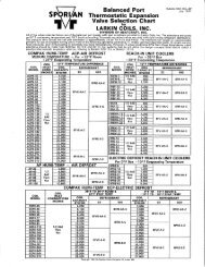
To adjust these valves, remove the cap and turn the adjustment<br />
nut with a 5/16" hex wrench for fully adjustable<br />
models (ADRS(E)-2, ADRP(E)-3, ADRH(E)-6) and 3/16" hex<br />
wrench for the AR models. The fully adjustable model<br />
ADRI(E)-1-1/4 has a 3/8” adjustment screw on top of the<br />
adjustment housing. A clockwise rotation increases the setting<br />
and a counterclockwise rotation decreases the setting.<br />
CAUTION: Because of possible damage to the adjustment<br />
assembly (AR type), do not force the adjustment screw<br />
beyond the stops. Also, due to the air charge in the AR<br />
models, the remote bulb must be properly located. See<br />
the discussion on VALVE LOCATION.<br />
Adjusting these valves can be complicated because the load<br />
must be varied during the setting procedure and it is difficult<br />
to determine exactly when the bypass valve opens<br />
unless a pressure gauge can be located at the valve outlet.<br />
Therefore, sufficient load must be available in some form to<br />
raise the suction pressure above the desired valve setting.<br />
Once this is accomplished, the load can be slowly decreased<br />
until the DBV opens (a hissing sound and/or an accompanying<br />
pressure rise at the outlet connection will indicate<br />
that the bypass valve has opened).<br />
1 Replacement part not available.<br />
2 Part is not available separately, but is included<br />
with the Replacement Springs Kits.<br />
3 Part is available separately. See chart above.<br />
4 Part is available as a replacement element.<br />
See chart above.<br />
5 Part available for (A)DRHE-6 only in KH-6 kit.<br />
Adjustable Element
Page 4<br />
SERVICE INSTRUCTIONS<br />
There are several possible causes for system malfunction<br />
when hot gas bypass for capacity controls is used. As with<br />
any form of troubleshooting, it is essential to know the<br />
existing operating temperatures and pressures before the<br />
malfunction can be determined. Once the actual malfunction<br />
is pinpointed, it is easier to isolate the cause and then<br />
take appropriate corrective action.<br />
There are two basic malfunctions of a discharge bypass<br />
valve: failure to open and failure to close. And since all<br />
<strong>Sporlan</strong> DBV’s can be disassembled, many “causes” can be<br />
easily remedied. Replacement elements are available for all<br />
types. ADRI(E)-1-1/4 models manufactured prior to July<br />
1994 do not have a replaceable element. The entire valve<br />
must be replaced.<br />
VALVE<br />
TYPE<br />
ADRI-1-1/<br />
4<br />
ADRIE-1-1/<br />
4<br />
ADRS-2<br />
ADRSE-2<br />
ADRP-3<br />
ADRPE-3<br />
ADRH-6<br />
ADRHE-6<br />
DRP-3-AR<br />
DRPE-3-AR<br />
DRH-6-AR<br />
DRHE-6-AR<br />
DRS-2<br />
DRSE-2<br />
DRP-3<br />
DRPE-3<br />
DRH-6<br />
DRHE-6<br />
FULLY<br />
ADJUSTABLE<br />
SERVICE TIPS<br />
Due to the design of each valve type, it is easiest to consider<br />
them separately. The table below shows the various valve<br />
types, the possible causes, and the remedies for the two<br />
possible malfunctions.<br />
Hot gas may be required for other system functions besides<br />
hot gas bypass capacity control, e.g., hot gas defrost and<br />
head pressure control. Normally, these functions will not<br />
interfere with each other. However, compressor cycling on<br />
low suction pressure may be experienced on system startup<br />
when the discharge bypass valve is operating and other<br />
functions require hot gas. For example, the head pressure<br />
control valve (e.g., <strong>Sporlan</strong> ORD-4 type) requires hot gas to<br />
adequately pressurize the receiver and liquid line to get the<br />
thermostatic expansion valve operating properly. In this<br />
case, the discharge bypass valve should be prevented from<br />
functioning by keeping the hot gas solenoid valve closed<br />
until adequate liquid line or suction pressure is obtained.<br />
PRINTED IN U. S. OF A. FORM <strong>SD</strong>-<strong>57</strong>-803<br />
.<br />
M<br />
ODELS<br />
- ADR<br />
TYPE<br />
MALFUNCTION CAUSE REMEDY<br />
Failure to<br />
open<br />
1. Dirt<br />
or<br />
foreign<br />
material<br />
in<br />
valve<br />
1.<br />
Disassemble<br />
valve<br />
and<br />
clean<br />
1.<br />
Dirt<br />
or<br />
foreign<br />
material<br />
in<br />
valve<br />
1.<br />
Disassemble<br />
valve<br />
and<br />
clean<br />
2.<br />
Diaphragm<br />
failure<br />
2.<br />
Replace<br />
element<br />
only<br />
Failure<br />
to<br />
close<br />
3.<br />
Equalizer<br />
passageway<br />
plugged<br />
3.<br />
Disassemble<br />
valve<br />
and<br />
clean<br />
4.<br />
External<br />
equalizer<br />
not<br />
connected<br />
or<br />
equalizer<br />
line<br />
pinched<br />
shut<br />
4.<br />
Connect<br />
or<br />
replace<br />
equalizer<br />
line<br />
5.<br />
Internal<br />
spring<br />
overheated<br />
5.<br />
Replace<br />
valve<br />
1.<br />
Dirt<br />
or<br />
foreign<br />
material<br />
in<br />
valve<br />
1.<br />
Disassemble<br />
valve<br />
and<br />
clean<br />
Failure<br />
to<br />
open<br />
2.<br />
Equalizer<br />
passageway<br />
plugged<br />
2.<br />
Disassemble<br />
valve<br />
and<br />
clean<br />
3.<br />
External<br />
equalizer<br />
not<br />
connected<br />
or<br />
equalizer<br />
line<br />
pinched<br />
shut<br />
3.<br />
Connect<br />
or<br />
replace<br />
equalizer<br />
line<br />
Failure<br />
to<br />
close<br />
1.<br />
Dirt<br />
or<br />
foreign<br />
material<br />
in<br />
valve<br />
2.<br />
Diaphragm<br />
failure<br />
1.<br />
Disassemble<br />
valve<br />
and<br />
clean<br />
2.<br />
Replace<br />
element<br />
only<br />
" LIMITED"<br />
ADJUSTABLE<br />
MODELS<br />
- DR<br />
- AR<br />
TYPE<br />
1.<br />
Dirt<br />
or<br />
foreign<br />
material<br />
in<br />
valve<br />
1.<br />
Disassemble<br />
valve<br />
and<br />
clean<br />
Failure<br />
to<br />
open<br />
2.<br />
Diaphragm<br />
failure<br />
2.<br />
Replace<br />
element<br />
only<br />
3.<br />
Air<br />
charge<br />
in<br />
element<br />
lost<br />
3.<br />
Replace<br />
element<br />
only<br />
1.<br />
Dirt<br />
or<br />
foreign<br />
material<br />
in<br />
valve<br />
1.<br />
Disassemble<br />
valve<br />
and<br />
clean<br />
Failure<br />
to<br />
close<br />
2.<br />
Equalizer<br />
passageway<br />
plugged<br />
3.<br />
External<br />
equalizer<br />
not<br />
connected<br />
or<br />
equalizer<br />
line<br />
pinched<br />
shut<br />
2.<br />
Disassemble<br />
valve<br />
and<br />
clean<br />
3.<br />
Connect<br />
or<br />
replace<br />
equalizer<br />
line<br />
4.<br />
Internal<br />
spring<br />
overheated<br />
4.<br />
Replace<br />
valve<br />
1.<br />
Dirt<br />
or<br />
foreign<br />
material<br />
in<br />
valve<br />
1.<br />
Disassemble<br />
valve<br />
and<br />
clean<br />
2.<br />
Diaphragm<br />
failure<br />
2.<br />
Replace<br />
element<br />
only<br />
Failure<br />
to<br />
open<br />
3.<br />
Equalizer<br />
passageway<br />
plugged<br />
3.<br />
Disassemble<br />
valve<br />
and<br />
clean<br />
4.<br />
External<br />
equalizer<br />
not<br />
connected<br />
or<br />
equalizer<br />
line<br />
pinched<br />
shut<br />
4.<br />
Connect<br />
or<br />
replace<br />
equalizer<br />
line<br />
5.<br />
Air<br />
charge<br />
in<br />
element<br />
lost<br />
5.<br />
Replace<br />
element<br />
only<br />
Failure to<br />
close<br />
1. Dirt<br />
or<br />
foreign<br />
material<br />
in<br />
valve<br />
1.<br />
Disassemble<br />
valve<br />
and<br />
clean<br />
NON-ADJUSTABLE<br />
MODELS<br />
- REMOTE<br />
BULB<br />
and<br />
DOME<br />
TYPE<br />
1.<br />
Dirt<br />
or<br />
foreign<br />
material<br />
in<br />
valve<br />
1.<br />
Disassemble<br />
valve<br />
and<br />
clean<br />
Failure<br />
to<br />
open<br />
2.<br />
Diaphragm<br />
failure<br />
2.<br />
Replace<br />
element<br />
only<br />
3.<br />
Air<br />
charge<br />
in<br />
element<br />
lost<br />
3.<br />
Replace<br />
element<br />
only<br />
1.<br />
Dirt<br />
or<br />
foreign<br />
material<br />
in<br />
valve<br />
1.<br />
Disassemble<br />
valve<br />
and<br />
clean<br />
Failure<br />
to<br />
close<br />
2.<br />
Equalizer<br />
passageway<br />
plugged<br />
3.<br />
External<br />
equalizer<br />
not<br />
connected<br />
or<br />
equalizer<br />
line<br />
pinched<br />
shut<br />
2.<br />
Disassemble<br />
valve<br />
and<br />
clean<br />
3.<br />
Connect<br />
or<br />
replace<br />
equalizer<br />
line<br />
4.<br />
Internal<br />
spring<br />
overheated<br />
4.<br />
Replace<br />
valve<br />
1.<br />
Dirt<br />
or<br />
foreign<br />
material<br />
in<br />
valve<br />
1.<br />
Disassemble<br />
valve<br />
and<br />
clean<br />
2.<br />
Diaphragm<br />
failure<br />
2.<br />
Replace<br />
element<br />
only<br />
Failure<br />
to<br />
open<br />
3.<br />
Equalizer<br />
passageway<br />
plugged<br />
3.<br />
Disassemble<br />
valve<br />
and<br />
clean<br />
4.<br />
External<br />
equalizer<br />
not<br />
connected<br />
or<br />
equalizer<br />
line<br />
pinched<br />
shut<br />
4.<br />
Connect<br />
or<br />
replace<br />
equalizer<br />
line<br />
5.<br />
Air<br />
charge<br />
in<br />
element<br />
lost<br />
5.<br />
Replace<br />
element<br />
only<br />
Failure to<br />
close<br />
1. Dirt<br />
or<br />
foreign<br />
material<br />
in<br />
valve<br />
1.<br />
Disassemble<br />
valve<br />
and<br />
clean<br />
WARNING: Serious injury could result from an explosion caused by the rapid expansion of trapped liquid refrigerant subjected to high temperature.<br />
ALWAYS REMOVE THE REFRIGERANT FROM THE SYSTEM BY USING REFRIGERANT RECOVERY/RECYCLING EQUIPMENT BEFORE<br />
APPLYING HEAT TO REMOVE SYSTEM COMPONENTS. Break the element charging cap tube on valve dome by hand or with a clean cut tool to eliminate<br />
any trapped refrigerant. DO NOT use side cutters which may seal the opening.