THERMOSTATIC EXPANSION VALVES ... - Sporlan Online
THERMOSTATIC EXPANSION VALVES ... - Sporlan Online
THERMOSTATIC EXPANSION VALVES ... - Sporlan Online

Create successful ePaper yourself
Turn your PDF publications into a flip-book with our unique Google optimized e-Paper software.
<strong>THERMOSTATIC</strong> <strong>EXPANSION</strong> <strong>VALVES</strong><br />
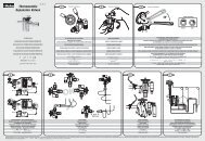
IDENTlFlCATlON<br />
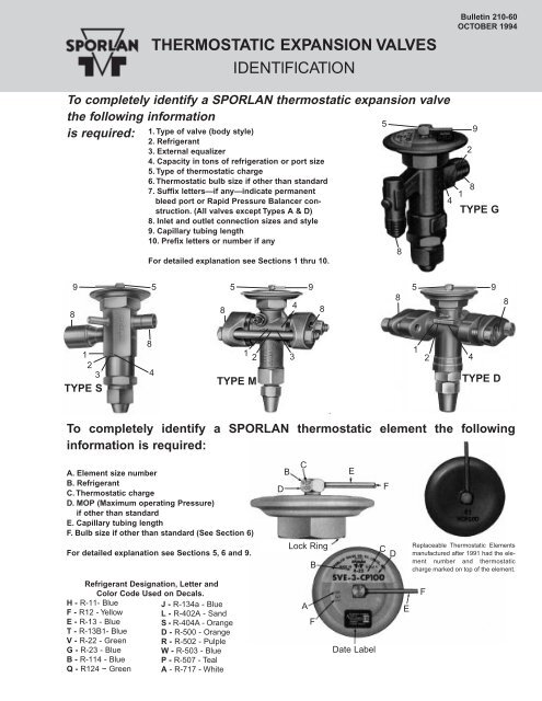
To completely identify a SPORLAN thermostatic expansion valve<br />
the following information<br />
5<br />
is required:<br />
8<br />
9<br />
1<br />
2<br />
3<br />
TYPE S<br />
1.Type of valve (body style)<br />
2. Refrigerant<br />
3. External equalizer<br />
4. Capacity in tons of refrigeration or port size<br />
5.Type of thermostatic charge<br />
6.Thermostatic bulb size if other than standard<br />
7. Suffix letters—if any—indicate permanent<br />
bleed port or Rapid Pressure Balancer construction.<br />
(All valves except Types A & D)<br />
8. Inlet and outlet connection sizes and style<br />
9. Capillary tubing length<br />
10. Prefix letters or number if any<br />
For detailed explanation see Sections 1 thru 10.<br />
8<br />
Bulletin 210-60<br />
OCTOBER 1994<br />
To completely identify a SPORLAN thermostatic element the following<br />
information is required:<br />
A. Element size number<br />
B. Refrigerant<br />
C.Thermostatic charge<br />
D. MOP (Maximum operating Pressure)<br />
if other than standard<br />
E. Capillary tubing length<br />
F.Bulb size if other than standard (See Section 6)<br />
For detailed explanation see Sections 5, 6 and 9.<br />
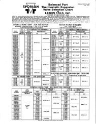
Refrigerant Designation, Letter and<br />
Color Code Used on Decals.<br />
H -R-11- Blue<br />
J -R-134a -Blue F -R12 -Yellow L -R-402A -Sand E -R-13 -Blue S -R-404A -Orange<br />
T -R-13B1- Blue D -R-500 -Orange V -R-22 -Green R -R-502 -Pulple G -R-23 -Blue W -R-503 -Blue B -R-114 -Blue P -R-507 -Teal Q -R124 ~ Green A -R-717 -White 5<br />
4<br />
8<br />
5<br />
TYPE M<br />
1 2 3<br />
D<br />
B<br />
4<br />
C<br />
9<br />
8<br />
Lock Ring<br />
A<br />
B<br />
F<br />
E<br />
Date Label<br />
F<br />
C D<br />
8<br />
8<br />
E<br />
5<br />
1<br />
2<br />
4<br />
1 8<br />
TYPE G<br />
TYPE D<br />
Replaceable Thermostatic Elements<br />
manufactured after 1991 had the element<br />
number and thermostatic<br />
charge marked on top of the element.<br />
F<br />
2<br />
4<br />
9<br />
9<br />
8
Page 2 — Bulletin 210-60<br />
1.TYPE VALVE -<strong>Sporlan</strong> thermostatic expansion valves<br />
are available in three body styles — SAE flare, ODF solder,<br />
or flange. The first letter or letters stamped on the<br />
valve body and shown on the label designates the valve<br />
type. Valve types are listed below.<br />
Valve Types (STANDARD)<br />
BF SAE Flare<br />
C SAE Flare<br />
D FPT or Socket Weld<br />
EBF Extended ODF Solder<br />
EBS Extended ODF Solder<br />
F SAE Flare<br />
G SAE Flare<br />
EG ODF Solder<br />
H ODF Solder Flange<br />
M ODF Solder Flange<br />
Nl SAE Flare<br />
O ODF Solder<br />
P ODF Solder<br />
2.REFRIGERANT -<strong>Sporlan</strong> valves are available for use with<br />
most popular refrigerants. The letter stamped on the valve<br />
body following the valve type and shown on the label designates<br />
the refrigerant. Refrigerant designations are as follows:<br />
H -R-11-Blue<br />
F -R-12 - Yellow<br />
E -R-13 - Blue<br />
T -R-13B1 - Blue<br />
v -R22 - Green<br />
G -R-23 - Blue<br />
B -R-114-Blue<br />
Q -R-124 - Green<br />
3. EXTERNAL EQUALIZER -The letter “E” immediately<br />
following the letter designating the refrigerant is used to<br />
denote an external equalizer connection. Physical inspection<br />
of the valve will reveal whether or not an external<br />
equalizer connection has been provided.<br />
4. CAPACITY IN TONS of REFRIGERATlON or PORT<br />
SIZE -For all current production valves except the Types<br />
(E)BF & SBF, the number following the letters indicates<br />
the valve’s nominal capacity rating in tons. For example, a<br />
valve marked GF-1 is a Type G valve for Refrigerant 12<br />
with a one ton nominal capacity rating. A valve marked<br />
SVE-5 is an externally equalized Type S valve for<br />
Refrigerant 22 with a five ton nominal capacity rating.<br />
All current production Types (E)BF and SBF valves, and Type<br />
(E)BS valves, manufactured prior to 1992 use a letter code<br />
designation to indicate its capacity rating. Letter codes are<br />
listed in Table A along with their nominal capacity ranges.<br />
TABLE-A — (E)BF & (E)BS CAPACITY CODES<br />
Valve Type<br />
(E)BF<br />
SBF<br />
Capacity<br />
Code<br />
RIVE SAE Flare or ODF Solder<br />
S ODF Solder<br />
SBF Extended ODF Solder<br />
V ODF Solder Flange<br />
W ODF Solder Flange<br />
A FPI or Socket Weld<br />
Valve Types (OEM)<br />
Bl SAE Flare or ODF Solder<br />
FB SAE Flare or ODF Solder<br />
K ODF Solder<br />
I SAE Flare or ODF Solder<br />
X SAE Flare or ODF Solder<br />
J -R-134a - Blue<br />
L -R-402A - Sand<br />
S -R-404A - orange<br />
D -R-500 - orange<br />
R -R-502 - Purple<br />
W -R-503 - Blue<br />
P -R-507 - Teal<br />
A -R-717-White<br />
Nominal Capacity Range<br />
R-12 R-22 R-502<br />
AA 1/8 — 1/3 1/8 — 2/3 1/8 — 1/3<br />
A 1/2 — 1 3/4 — 1-1/2 1/2 — 1<br />
B 1-1/4 — 1-3/4 1-3/4 — 3 1-1/4 — 2<br />
C 2 — 3 3-1/4 — 5-1/2 2-1/4 — 3<br />
(E)BS D 4 — 7 7 — 11 4 — 7-1/2<br />
For ammonia valves, (Types A & D) the valve’s nominal<br />
capacity rating is determined by the outlet discharge tube<br />
size and the port size in the valve body. Therefore, the rating<br />
can be read from the valve label as shown in Figure 1,<br />
or it can be determined by the port and discharge tube size.<br />
Ammonia valves are the only valves which have their port<br />
size stamped on the body. Prior to January 1954, the valve<br />
type and port size were stamped on the topside of the outlet<br />
flange for both the Types A & D valve. After this time, this<br />
marking was relocated to a boss on the side of the valve<br />
body for the Type D valve only. See Page 1.<br />
Listed in Table B are the port and discharge tube sizes,<br />
and their associated nominal capacity ratings for the<br />
Types A & D valves.<br />
TABLE-B — DISCHARGE TUBE & PORT SIZES<br />
Valve Type<br />
D<br />
A<br />
Nominal Capacity<br />
Rating (R-717)<br />
Port<br />
Size (in)<br />
Discharge<br />
Tube Orifice (in)<br />
1 1/16 1/32<br />
2 1/16 1/16<br />
5 7/64 5/64<br />
10 3/16 7/64<br />
15 3/16 5/32<br />
20 5/16 1/8<br />
30 5/16 5/32<br />
50 3/8 3/16<br />
75 3/8 none<br />
100 7/16 none<br />
5. REFRIGERANT and <strong>THERMOSTATIC</strong> CHARGE IN ELE-<br />
MENT -The label on the power element diaphragm case<br />
carries designations pertaining to type — charge — capacity<br />
and refrigerant. Immediately below the label and<br />
stamped in the top of the diaphragm case is a number<br />
which indicates the lock ring thread size of the element.<br />
This number designates the “element size.” See Figure 1.<br />
Prior to 1959 a single digit was used — e.g. 8 — after that<br />
time and prior to 1960 a second digit was added to indicate a<br />
modified construction — e.g. 81. Subsequent to 1960 this second<br />
digit was changed from “1” to “2” and in 1966 from “2” to<br />
“3” — e.g. 83 — to indicate further modifications. All current<br />
elements are designated with the suffix “3” with the exception<br />
of numbers 7 and 1 — their designations are 7 and 12<br />
respectively. See the valve availability guide, Table-F, Page<br />
4, for a cross reference between valves and element sizes.<br />
Further identification of the element is provided by the use<br />
of two or three letters and sometimes two or three numbers<br />
marked on top of the element. The first letter indicates the<br />
refrigerant and the second letter (and third if used) the<br />
selective charge of the element. Numbers, if used, indicate<br />
a special MOP or maximum operating pressure. (For<br />
refrigerant identification refer to Section 2). Prior to 1992,<br />
the refrigerant code and selective charge designation were<br />
stamped on the side of the capillary button on top of the<br />
diaphragm case. See Figure 1. The Selective Charges C,<br />
CP, Z, ZP, VGA, and X are generally applied in the range<br />
of temperatures shown in Table-C.<br />
TABLE-C<br />
RECOMMENDED <strong>THERMOSTATIC</strong> CHARGES<br />
REFRIGERANT<br />
AIR CONDITIONING<br />
OR<br />
HEAT PUMP<br />
COMMERCIAL<br />
REFRIGERATION<br />
+50°F. to -10°F.<br />
LOW TEMPERATURE<br />
REFRIGERATION<br />
0°F. to -40°F.<br />
EXTREME TEM-<br />
PERATURE<br />
REFRIGERATION<br />
-40°F. to -100°F.<br />
12 FCP60 FC FZ, FZP —<br />
22 VCP100, VGA VC VZ, VZP40 VX<br />
134a JCP60 JC — —<br />
401A XCP60 XC — —<br />
402A — LC LZ, LZP LX<br />
404A SCP115 SC SZ, SZP SX<br />
502 RCP115 RC RZ, RZP RX<br />
507 — PC PZ, PZP PX<br />
The <strong>Sporlan</strong> Type ZP thermostatic charges have essentially the same<br />
characteristics as the conventional Z Cross charges with one exception.<br />
They produce a pressure limit or MOP without the use of<br />
mechanical devices used in double diaphragm valves. The ZP<br />
charges are not intended as replacements for the Z charges — they<br />
should only be used where a definite pressure limit is required to prevent<br />
motor overloading.<br />
A conventional Type L liquid charge is also available for all commonly<br />
used refrigerants in most of our element sizes.<br />
The Types U, O, and K charges formerly used on Ammonia<br />
valves have been redesignated Types L, C, and Z respectively,<br />
to make them conform with the corresponding<br />
charges used on other refrigerants.
A Type VCP, Refrigerant 22 air conditioning or heat pump<br />
charge with a 100 psig limit is stamped “VCP100.” See<br />
Figure-1 Page 1.<br />
Table D lists the standard Type “P” charge MOP’s.<br />
Refrigerant<br />
TABLE-D<br />
GA, CP,and ZP Charged Valves<br />
① Thermostatic<br />
Charge<br />
Mop-PSIG<br />
Factory<br />
Air Test<br />
Nominal<br />
System<br />
12<br />
FCP60<br />
FZP<br />
60<br />
20<br />
50<br />
12<br />
VGA 110 ② 100<br />
22<br />
VCP100<br />
VCP40<br />
100<br />
40<br />
90<br />
30<br />
VZP 30 20<br />
134a JCP60 60 50<br />
401A XCP60 60 50<br />
402A LZP 45 35<br />
404A<br />
SCP115<br />
SZP<br />
115<br />
45<br />
105<br />
35<br />
502<br />
RCP115<br />
RZP<br />
115<br />
45<br />
105<br />
35<br />
507 PZP 45 35<br />
①A numerical suffix on a thermostatic charge designation indicates a<br />
special MOP.Omission of the number indicates standard MOP as<br />
shown.<br />
②Not as well defined as the other Type “P”charges listed in this table.<br />
Example: VCP100 charge has a special air test MOP of 100.<br />
The above system of identification of elements has been in<br />
effect since 1936. However, from 1936 to 1943 the letters<br />
indicating “refrigerant” and “type of charge” were stamped<br />
on the top of the diaphragm case along with the element<br />
size number, instead of on the diaphragm case button.<br />
Prior to 1936 elements were identified by a serial number.<br />
Beginning in 1948 a decal was affixed to the thermostatic<br />
element. Therefore, element identification must include<br />
lock ring size number, refrigerant, charge, capillary tubing<br />
length and pressure limit where applicable.<br />
6.<strong>THERMOSTATIC</strong> BULB SIZE - The following bulb sizes<br />
listed in Table E are standard and are supplied in the<br />
TABLE-E<br />
STANDARD BULB SIZES — Inches<br />
Bulletin 210-60 — Page 3<br />
majority of instances. When a non-standard oversized<br />
bulb is used on a thermostatic element a third digit, “1”, is<br />
added to the “element size” designation — e.g. “831” for a<br />
Number 83 element with a large bulb. (See Section 5, Page<br />
2 for complete explanation of element nomenclature).<br />
7.PERMANENT BLEED PORT or RAPID PRESSURE BAL-<br />
ANCER CONSTRUCTION — Air conditioning or refrigeration<br />
systems employing split phase or PSC motors which<br />
have low starting torques, require high to low side pressure<br />
equalization prior to restarting.<br />
A permanent bleed port valve incorporates an internal<br />
bypass or bleed that remains open at all times. Even when the<br />
valve closes on system shut down, the bleed permits a continued<br />
flow of refrigerant until the pressures are equalized.<br />
In addition to the usual body stampings signifying body<br />
type, refrigerant etc., the permanent bleed rate is also<br />
stamped on the body for percent bleeds up to and including<br />
50%. For example a bleed rate equivalent to 10% of nominal<br />
capacity is shown as “BP/10.”<br />
Permanent bleeds in excess of 50% of nominal capacity are<br />
not stamped on the body — a Y number prefix is used to<br />
signify this special feature. (See Section 10, Page 4).<br />
The RPB Valve presents a major change in the design of<br />
thermostatic expansion valves. The RPB bleed is actuated<br />
only on the off cycle. Immediately after shut down the<br />
evaporator pressure rises and the pin carrier moves to the<br />
closed position as in a conventional valve. However, with<br />
the RPB design the pin carrier continues its motion and<br />
opens the secondary spring loaded bleed port allowing<br />
rapid equalization of high and low side pressures. Upon<br />
restarting the compressor the secondary bleed port closes<br />
and the valve functions in the normal manner. If the RPB<br />
feature is incorporated in a valve, the letters “RPB” are<br />
stamped on the body. For example—SVE-3-CPl00-RPB.<br />
8. INLET and OUTLET CONNECTION SIZES and STYLE-<br />
The style — flare, flanged or solder — and the size of the<br />
inlet and outlet connections can be determined visually.<br />
9. CAPILLARY TUBING LENGTH - <strong>Sporlan</strong> Thermostatic<br />
Expansion Valves are generally supplied with elements<br />
having capillary tubing in increments of 30” and 5 feet.<br />
other capillary tube lengths are also available. The length<br />
of the capillary tubing can be easily measured.<br />
Refrigerant Charge<br />
NI (non-replaceable) Number 43<br />
Element Size<br />
Number 53 Number 83 Number 33 Number 63<br />
12<br />
FCP60<br />
FC<br />
FZ<br />
0.50 OD X 3.00<br />
0.50 OD X 3.00<br />
0.38 OD X 4.50<br />
0.50 OD X 3.50<br />
0.75 OD X 4.00<br />
0.50 OD X 5.00<br />
0.50 OD X 5.00<br />
0.88 OD X 6.00<br />
FZP 0.50 OD X 3.50 0.75 OD X 4.00<br />
VGA<br />
VCP100<br />
0.75 OD X 2.00 0.75 OD X 2.00 0.75 OD X 2.00 0.75 OD X 4.00 0.75 OD X 4.00<br />
22<br />
VC<br />
VZ<br />
0.50 OD X 3.00 0.50 OD X 3.50 0.50 OD X 3.50<br />
0.75 OD X 4.00 0.88 OD X 6.00<br />
VZP 0.50 OD X 3.00<br />
VX N/A 0.75 OD X 4.00 0.75 OD X 4.00<br />
134a<br />
JCP60<br />
JC<br />
RCP115<br />
0.50 OD X 3.00 0.50 OD X 3.50 0.50 OD X 3.50<br />
0.75 OD X 4.00<br />
0.50 OD X 5.00<br />
0.88 OD X 6.00<br />
502<br />
RC<br />
RZ<br />
RZP<br />
0.50 OD X 3.00 0.50 OD X 3.50 0.50 OD X 3.50<br />
0.75 OD X 4.00 0.88 OD X 6.00<br />
RX N/A 0.75 OD X 4.00 0.75 OD X 4.00
Page 4 — Bulletin 210-60<br />
10.PREFIX LETTERS -N -Indicates non-adjustable superheat<br />
construction when used as prefix to basic valve type<br />
specification. — e.g. NSVE-3-GA. Adjustable bottom cap<br />
assembly kits are available for field conversion to a standard<br />
adjustable valve. See Page 5.<br />
H - Indicates hermetic construction and Manufacturer’s<br />
Warranty generally is void if the valve is removed from system<br />
or disassembled. Therefore, replacements and repair parts are<br />
NOT available. All valves of this type are also nonadjustable.<br />
Y-Number -When a basic valve type is preceded by the<br />
prefix Y and a number, it indicates a special construction<br />
made for a particular equipment manufacturer. While<br />
some of the parts may be standard and interchangeable,<br />
complete valves are generally available only through the<br />
equipment manufacturer. A typical designation would be<br />
Y335-CVE-2-CP100. This particular valve has a 60% permanent<br />
bleed and a special superheat spring and should<br />
not be replaced by a standard valve.<br />
VALVE DATE -All new valves are marked to show the week<br />
and year in which they were manufactured. The date code<br />
consists of either three or four digits: a one or two digit week<br />
code, and a two digit year code. Thus, “889” and “1189” refer<br />
to the eighth and eleventh week of 1989. Since a full year<br />
exceeds 52 weeks by either one or two days, a 53rd week will<br />
occasionally be assigned, extending into the following year.<br />
These markings indicate the date of manufacture of the<br />
③ Valve<br />
Type<br />
VALVE AVAILABILITY GUIDE<br />
TABLE-F — CURRENT VALVE TYPES<br />
12, 134a, 401A<br />
NOMINAL CAPACITY<br />
Tons of Refrigeration<br />
22 402A, 404A, 502 507 717<br />
valve only and have no reference to valve type, refrigerant,<br />
capacity, or type of charge. Prior to 1989, a sticker placed on<br />
the thermostatic element indicated what quarter and year<br />
the valve was manufactured. Thus, D87 indicates the last<br />
quarter of 1987 and C89 indicates the third quarter of 1989.<br />
DATE CODE STICKER PRIOR TO 1989<br />
TO REPLACE ELEMENT<br />
SPECIFY-<br />
SIZE NUMBER<br />
REFRIGERANT<br />
CHARGE<br />
TUBING LENGTH<br />
CURRENT DATE CODE STICKER<br />
(See Figure-1, Page 1, for location on element.)<br />
FURTHER AIDS TO IDENTIFICATlON - Valve identification<br />
markings illustrated on Page 1 apply to all types presently<br />
manufactured by <strong>Sporlan</strong> Valve Company. Types G, S,<br />
M and D are used as examples. As an aid in identifying discontinued<br />
types of valves which are still in operation, the<br />
following data applies. From 1934 through 1936, all valves<br />
were identified by means of a serial number. Since 1937<br />
the valve type and refrigerant have been stamped on the<br />
body of the valve. Capacities of valves from 1936 to 1944<br />
were shown in either port sizes or tons capacity. However,<br />
since January 1944, all valves except Ammonia valves<br />
have been marked in tons capacity rather than port sizes.<br />
Numbers cast into the external valve parts merely indicate<br />
the pattern number of the valve body and are of no value<br />
in determining refrigerant, capacity or type of thermostatic<br />
charge. They are listed in the valve availability guide<br />
Table F, below.<br />
Connection<br />
Style<br />
Element<br />
Size No.<br />
① Body<br />
Casting<br />
No.<br />
⑧ NI 1/8, 1/4, 1/2, 1 1/4, 1/2, 1 1/4, 1/2, 1<br />
SAE Flare<br />
SAE Flare<br />
⑧ RIVE — 2, 3, 4, 5 —<br />
or<br />
ODF Solder<br />
F 1/8, 1/4, 1/2, 1, 1-1/2, 2 1/4, 1/2, 1, 1-1/2, 2, 2-1/2, 3 1/8, 1/4, 1/2, 1, 1-1/2, 2<br />
43<br />
⑦ (E)BF<br />
and SBF<br />
NOMINAL CAPACITY CODES AA, A, B, & C<br />
SAE Flare<br />
or<br />
Q<br />
1/6, 1/4, 1/2, 1, 1-1/2, 2,<br />
2-1/2<br />
1/3, 3/4, 1, 1-1/2, 2-1/2, 3-<br />
1/2, 5<br />
1/6, 1/4, 1/2, 1, 1-1/2,<br />
2, 3<br />
ODF Solder<br />
—<br />
⑥ G<br />
EG<br />
1/8, 1/4, 1/2, 1-1/2, 2<br />
1/5, 1/3, 1/2, 1, 1-1/2, 2, 2-<br />
1/2, 3<br />
1/8, 1/4, 1/2, 1, 1-1/2, 2<br />
SAE Flare<br />
ODF Solder<br />
53<br />
⑥ C<br />
S<br />
EBS<br />
2-1/2, 3, 5<br />
2, 2-1/2, 3, 5, 6<br />
7<br />
4, 5, 8<br />
2, 3, 4, 5, 8, 10<br />
11<br />
3, 4, 6<br />
2, 3, 4, 6, 7<br />
7-1/2<br />
—<br />
SAE Flare<br />
ODF Solder<br />
83<br />
④ P<br />
④ H<br />
1-1/2, 3, 4, 5, 8, 12 2-1/2, 5-1/2, 7, 11, 16, 20 1-1/2, 3, 4, 6-1/2, 9, 12 ODF<br />
Solder<br />
33<br />
M<br />
5, 7-1/2, 11, 13, 15, 20,<br />
25<br />
8, 12, 18, 21, 26, 34, 42 9, 15, 20, 25, 30 Flange 63 107-E<br />
O<br />
83<br />
33<br />
6, 9, 12, 16<br />
23, 32, 40<br />
10, 15, 20, 30<br />
40, 55, 70<br />
6, 9, 12, 21<br />
30, 35, 45 ODF Solder<br />
83<br />
33<br />
—<br />
K<br />
V<br />
35, 45, 55 52, 70, 100 38, 50, 70<br />
ODF Solder<br />
63 707-A<br />
W 80, 110 135, 180 100, 130 Flange ② 63 and 7 707-B<br />
D<br />
A<br />
— — —<br />
1, 2, 5, 10,<br />
15<br />
20, 30, 50,<br />
75, 100<br />
Pipe Flange<br />
23<br />
12<br />
⑤ 207A<br />
107<br />
NOTE:Adapter Kit K-1178 allows the use of current Type large H to replace obsoleted Types small T and small H and also earlier obsoleted Types U, C and small O<br />
① Body casting number CANNOT be used for ordering.<br />
② Number 63 element used on WFE-80, WDE-95, WVE-135 and WRE-100.Number 7 element used on WFE-110, WDE-130, WVE-180, and WRE-130.<br />
③ In addition to the standard line of thermostatic expansion valves listed here, special valve types are manufactured to fill OEM requirements.These valves<br />
include Types Bl, I, X and FB valves.For replacement valves, contact either the OEM, your <strong>Sporlan</strong> Wholesaler or <strong>Sporlan</strong> Valve Company.<br />
④ The Types P and H valves were re-rated october 1970 in conformance with ARI Standard 750 as shown in the table.<br />
⑤ Casting number appears on early models only<br />
⑥ Types G and C valves which use the mechanical pressure limit ( PL-type) thermostatic element will have the MOP stamped on the diaphragm case button.The<br />
PL- type element is now obsolete.Refer to Bulletin 210-10-17 for additional information.<br />
⑦ Refer to Bulletins 10-10 and 10-10-3 for information on the application of Types (E) BF and SBF valves.<br />
⑧ During 1994, Types Nl and Rl valves were modified from a non-replaceable to a replaceable No.43 element design.<br />
DATE<br />
C-89<br />
TO REPLACE ELEMENT<br />
SPECIFY-<br />
SIZE NUMBER<br />
REFRIGERANT<br />
CHARGE<br />
TUBING LENGTH<br />
DATE<br />
889
REPLACEMENT PARTS ORDERING INFORMATlON<br />
INTERNAL VALVE PARTS KITS<br />
Internal valve parts kits are available for all <strong>Sporlan</strong> Thermostatic Expansion Valves — Both current and discontinued types — with the exception<br />
of the Types NI, AIF, X, I, and early models of the Types V and W, and some models of Types G, S, & C. These valves are constructed<br />
so that field replacement of internal parts is not recommended.<br />
VALVE<br />
TYPES<br />
Internal or<br />
External<br />
Equalizer<br />
TABLE-G — INTERNAL VALVE PARTS KITS for Current Valve Types<br />
NOMINAL CAPACITY<br />
Tons of Refrigeration<br />
12, 134a,<br />
402A, 404A,<br />
22<br />
401A<br />
502, 507<br />
KIT No.<br />
The following Kits contain: 1 Seat, 1 Pin & Carrier, 2 Push Rods, Push Rod Gauge.<br />
Type G valves with external equalizer, Type S valves dated B69 or later and<br />
Type C valves dated C70 or later have packless push rod construction. Due to<br />
the close tolerances, kits are not available for packless valves. The following<br />
internal parts kits are not to be used with packless valves.<br />
G Internal<br />
C<br />
S<br />
1/4 1/2 1/4 KP01 0002<br />
1/2 1 1/2 KP01 0005<br />
1 1-1/2 1 KP01 0010<br />
1-1/2 2-1/2 1-1/2 KP01 0015<br />
External 1 1-1/2 1 KP02 0010<br />
Internal<br />
KP03 0015<br />
1-1/2 2 1-1/2<br />
External KP02 0015<br />
Internal<br />
KP03 0020<br />
2 3 2<br />
External KP02 0020<br />
Internal<br />
KP03 0025<br />
2-1/2 4 3<br />
External KP02 0025<br />
Internal<br />
KP03 0030<br />
3 5 4<br />
External KP02 0030<br />
External 5 8 6 KP02 0050<br />
Internal 1/4 1/2 1/4 KP03 0002<br />
Internal<br />
KP03 0005<br />
1/2 1 1/2<br />
External KP02 0005<br />
Internal<br />
KP03 0010<br />
1 1-1/2 1<br />
External KP02 0010<br />
Internal<br />
KP03 0015<br />
1-1/2 2 1-1/2<br />
External KP02 0015<br />
Internal<br />
KP03 0020<br />
2 3 2<br />
External KP02 0020<br />
Internal<br />
KP03 0025<br />
2-1/2 4 3<br />
External KP02 0025<br />
Internal<br />
KP03 0030<br />
3 5 4<br />
External KP02 0030<br />
External 5 8 6 KP02 0050<br />
External 6 10 7 KP02 0060<br />
The following Kits contain: 1 Seat, 1 Pin & Carrier, 2 Push Rods, 1 Seal Cap Gasket,<br />
Push Rod Gauge.<br />
Int. or Ext. 1-1/2 2-1/2 1-1/2 KP12 0015<br />
P<br />
Int. or Ext. 3 5-1/2 3 KP12 0030<br />
Int. or Ext. 4 7 4 KP12 0040<br />
Int. or Ext. 5 11 6-1/2 KP12 0050<br />
Int. or Ext. 8 16 9 KP12 0080<br />
External 12 20 12 KP12 0120<br />
The following Kits contain: 1 Seat, 1 Pin & Carrier, 2 Push Rods, 2 Flange Gaskets,<br />
1 Seal Cap Gasket, Push Rod Gauge.<br />
Int. or Ext. 1-1/2 2-1/2 1-1/2 KP13 0015<br />
H<br />
Int. or Ext. 3 5-1/2 3 KP13 0030<br />
Int. or Ext. 4 7 4 KP13 0040<br />
Int. or Ext. 5 11 6-1/2 KP13 0050<br />
Int. or Ext. 8 16 9 KP13 0080<br />
External 12 20 12 KP13 0120<br />
VALVE<br />
TYPES<br />
Internal or<br />
External<br />
Equalizer<br />
NOMINAL CAPACITY<br />
Tons of Refrigeration<br />
12, 134a,<br />
402A, 404A,<br />
22<br />
401A<br />
502, 507<br />
KIT No.<br />
The following Kits contain: 1 Push Rod and Seal Assembly, Piston, Bottom Cap,<br />
Spring Guide, Seal Cap, (models with No. 33 elements include a Gasket), Push Rod<br />
Gauge, and set of instructions.<br />
6 10 6 KP19 0060<br />
O<br />
83<br />
33<br />
External<br />
9 15 9 KP19 0090<br />
12 20 12 KP19 0120<br />
16 30 21 KP19 0160<br />
23 40 30 KP20 0230<br />
32 55 35 KP20 0320<br />
40 70 45 KP20 0400<br />
The following Kits contain: 1 Seat, 1 Pin & Carrier, 2 Push Rods; the following<br />
gaskets: 1 Element, 2 Flanges, 1 Bottom Cap, 1 Seal Cap, Push Rod Gauge.<br />
M External<br />
5 8 — KP08 0050<br />
7-1/2 12 9 KP08 0075<br />
11 18 — KP08 0110<br />
13 21 15 KP08 0130<br />
15 26 20 KP08 0150<br />
20 34 25 KP08 0200<br />
25 42 30 KP08 0250<br />
The following Kits contain: 1 Eiement Gasket, 2 Flange Gaskets, 1 Bottom Cap<br />
Gasket, 1 Seal Cap Gasket, 1 Push Rod, 1 Push Rod Gauge, 1 Piston Assembly, 1<br />
Seat Refinishing Tool with Grit Cloth, 1 Set of Instructions. These Kits are for use<br />
with V Valves dated B65 or later and for W Valves dated A66 or later See Bulletin<br />
210-40-2.<br />
35 52 38 KP16 0350<br />
V, K External<br />
W External<br />
45 70 50<br />
55 100 70<br />
80 135 100<br />
110 180 130<br />
REFRIGERANT 717 (Ammonia)<br />
KP16 0450<br />
KP17 0800<br />
The following Kits contain: 1 Seat, 1 Pin & Carrier, 2 Push Rods; the following<br />
gaskets: 1 Element, 2 Flanges, 1 Bottom Cap, 1 Seal Cap, Push Rod Gauge.<br />
D<br />
A<br />
Int. or Ext. 1, 2 KP10 0010<br />
Int. or Ext. 5 KP10 0050<br />
Int. or Ext. 10, 15 KP10 0100<br />
Int. or Ext. 20, 30 KP09 0200<br />
Int. or Ext. 50, 75 KP09 0500<br />
Int. or Ext. 100 KP09 1000<br />
BOTTOM CAP ASSEMBLY KITS<br />
The following Kits allow field conversion from a non-adjustable to an adjustable valve<br />
type. See Section 10 on Page 4.<br />
VALVE TYPE KIT No. CONTENTS<br />
G, G(PL), C, C(PL), S, T KA-8<br />
P, H, U KA-3<br />
F, (E) BF, SBF KA-4<br />
*X KA-5X<br />
Bulletin 210-60 — Page 5<br />
Adjustable bottom cap<br />
assembly and seal cap<br />
*For Type-X Valve with Straight Through Connections only
9<br />
10<br />
11<br />
12<br />
Page 6 — Bulletin 210-60<br />
Valve Type<br />
A<br />
B<br />
9 12 C<br />
E<br />
F<br />
H<br />
(small)<br />
H<br />
(large)<br />
9 H<br />
(small)<br />
10<br />
11<br />
9<br />
J, K<br />
L<br />
O<br />
P<br />
Q<br />
14 R<br />
(small)<br />
13 R<br />
(large)<br />
13<br />
S<br />
11 T<br />
(small)<br />
10 T<br />
(large)<br />
11 U<br />
(small)<br />
U<br />
(large)<br />
12<br />
NOMINAL CAPACITY<br />
Tons of Refrigeration<br />
22 500<br />
Port<br />
Size<br />
Inches<br />
10 — — 5/16<br />
15 — — 3/8<br />
20 — — 7/16<br />
2 3 — 3/16<br />
3 5 — .209<br />
Connection<br />
Type<br />
ODF Solder<br />
Flange<br />
3 — — 3/16 ODF Solder<br />
6 — — 1/4<br />
Flange<br />
1 1-1/2 — 7/64<br />
2 3-1/2 — 3/16<br />
3 5 — .209<br />
1 1-1/2 — 7/64<br />
2 3-1/2 — 5/32<br />
3 5 — 3/16<br />
1/2 — — 1/16<br />
1 — — 7/64<br />
⑨ Element<br />
No.<br />
Body<br />
Casting No.<br />
1 107<br />
Body Material<br />
Prior to 1959 a single digit was used — e.g.8 — after that time and prior to 1960 a second digit was added to indicate a modified construction.Refer to Table J for current thermostatic elements.<br />
For the following valve types the flanges are DIRECTLY INTERCHANGEABLE, therefore the current valve type may be directly substituted tor the discontinued type.<br />
Discontinued Type Current Type<br />
Large O (9/32” Port) H<br />
P & Large T M & V<br />
Adapter Kit K-1178 allows the use of current Flanged Type H to replace obsoleted Flanged Types small T and small H and also earlier obsoleted Types U, C and small O ( ‘/4”Port and smaller)<br />
Manulactunsd prior to 1944. Manufactured prior to 1945. Manufactured prior to 1960.<br />
Grey<br />
Cast<br />
Iron<br />
ODF Solder 4 — Brass Bar S<br />
2 207<br />
Grey<br />
Cast<br />
Iron<br />
Replaced by<br />
Current<br />
Valve Type<br />
M<br />
H<br />
SAE Flare 4 — Brass Forging G, C<br />
SAE Flare 2 — Brass Forging G, C<br />
SAE Flare<br />
4 407-A<br />
Brass Forging<br />
3 — — 3/16 2 307-C CFE-3<br />
5 8 6 7/32<br />
— 10 — .228<br />
7-1/2 12 9 1/4<br />
— 15 — 17/64<br />
— 1/2 — 1/32<br />
1/2 1 — 1/16<br />
1 1-1/2 — 7/64<br />
1-1/2 2-1/2 — 1/8<br />
1/2 — — 1/16<br />
1 1-1/2 — 7/64<br />
2 3-1/2 — 5/32<br />
3 5 — 3/16<br />
6 11 — 1/4<br />
10 17 — 9/32<br />
2 3-1/2 — 5/32<br />
3 5 — 3/16<br />
6 10 — 1/4<br />
10 16 — 9/32<br />
10 — — 5/16<br />
15 — — 3/8<br />
20 — — 7/16<br />
— 21 — 11/32<br />
— 26 — 5/16<br />
— 34 — 3/8<br />
— 42 — 7/16<br />
— 1/2 — 1/32<br />
1/2 1 1/2 1/16<br />
1 1-1/2 1 7/64<br />
1-1/2 2-1/2 1-1/2 1/8<br />
ODF Solder<br />
Flange<br />
ODF Solder<br />
3 — Brass Bar H<br />
J-4<br />
K-5<br />
— Brass Bar S<br />
ODF Solder 2 — Brass Bar S, Small O<br />
ODF Solder<br />
Flange<br />
ODF Solder<br />
Flange<br />
2 — Brass Bar H<br />
1 107-C<br />
ODF Solder 6 —<br />
Grey<br />
Cast<br />
Iron<br />
Grey<br />
Cast<br />
Iron or Brass<br />
ODF Solder 8 — Brass Bar S<br />
3 — — 3/16<br />
ODF Angle<br />
807<br />
6 — — 1/4<br />
2<br />
Solder Flange<br />
10 — — 9/32 807-A<br />
10 — — 5/16<br />
15 — — 3/8<br />
20 — — 7/16<br />
1-1/2 2 — 5/32<br />
2 3 2-1/2 1/8<br />
2-1/2 4 3 5/32<br />
3 5 3-1/2 .209<br />
ODF Angle<br />
Solder Flange<br />
ODF Solder<br />
Flange<br />
1 507<br />
Grey<br />
Cast<br />
Iron<br />
Grey<br />
Cast<br />
Iron<br />
8 — Brass Bar S<br />
50 — — Double Port 1 707 Bronze Casting VFE-55<br />
2 3-1/2 — 3/*16 ODF Solder<br />
3 5 — .209<br />
Flange<br />
12 22 15<br />
17 30 21<br />
23 40 28<br />
TABLE-H — DISCONTINUED VALVE TYPES<br />
Double<br />
Port ODF Solder<br />
4 — Brass Bar H<br />
3<br />
— Brass Bar<br />
Z SEE PAGE 7 Permanent RI<br />
13 14<br />
G<br />
M<br />
M<br />
H<br />
M<br />
Small O,<br />
Large O
Valve<br />
Type<br />
NOMINAL CAPACITY<br />
Tons of Refrigeration<br />
717<br />
For footnote 11 ~ information, see bolltom of Page 6.<br />
TABLE-H (Con’t) — REFRIGERANT 717 (Ammonia)<br />
Port<br />
Size<br />
Inches<br />
Discharge<br />
Tube Orifice<br />
Inches<br />
CROSS-REFERENCE FOR CURRENT TYPES C, S, P, H, M, & V<br />
The Types P, H, M, and V valves were re-rated in August 1957 as shown in the table below. The re-rated Types P and H valves<br />
were later obsoleted or re-rated in October 1970 (with the exception of the PFE-5 and HFE-5), and replaced with the Types<br />
P and H valves listed below.<br />
15 In May 1966 the small T and small H valves were discontinued and the large H was made<br />
available in the lower nominal capacity ranges also.The large H may be adapted to existing<br />
small T and small H flanges by using adapter kit K-1178.<br />
Connection<br />
Type<br />
Element<br />
No.<br />
Body<br />
Casting No.<br />
Body<br />
Material<br />
1 1/16 1/32<br />
11 C,<br />
E, F, N<br />
2<br />
5<br />
10<br />
1/16<br />
7/64<br />
3/16<br />
1/16<br />
5/64<br />
7/64<br />
FPT (E)<br />
FPT Flange<br />
(C, F, N)<br />
—<br />
D<br />
15 3/16 1/8<br />
Grey<br />
J, K 100 7/16 — FPT Flange — — Cast AA(E)-100<br />
1 1/16 1/32<br />
Iron<br />
2 1/16 1/16<br />
PC, PN<br />
5 7/64 5/64 FPT Flange (AEV) —<br />
10 3/16 7/64<br />
15 3/16 1/8<br />
PORT<br />
SIZE<br />
Inches<br />
Prior to<br />
Aug 1957<br />
REFRIGERANT-12 REFRIGERANT-22 REFRIGERANT-500<br />
Aug 1957 to<br />
Oct 1970<br />
Current Prior to<br />
Aug 1957<br />
Aug 1957 to<br />
Oct 1970<br />
Current Prior to<br />
Aug 1957<br />
Aug 1957 to<br />
Oct 1970<br />
Replaced by<br />
Current<br />
Valve Type<br />
Current<br />
7/32 — PFE-5 PFE-5 PVE-8 PVE-8 PVE-11 PDE-5 PDE-6 PDE-5<br />
0.228 — — — — PVE-10 — — — —<br />
0.277 — — PFE-8 — — PVE-16 — — PDE-8<br />
1/4 PFE-6 PFE-7-1/2 PFE-12 PVE-11 PVE-12 PVE-20 PDE-8 PDE-9 PDE-14<br />
17/64 — — — — PVE-15 — — — —<br />
9/32 PFE-10 PFE-11 — PVE-17 PVE-18 — PDE-13 PDE-13 —<br />
15 7/32 — HFE-5 HFE-5 HVE-8 HVE-8 HVE-11 HDE-5 HDE-6 HDE-5<br />
0.228 — — — — HVE-10 — — — —<br />
0.277 — — HFE-8 — — HVE-16 — — HDE-8<br />
15 1/4 HFE-6 HFE-7-1/2 HFE-12 HVE-10 HVE-12 HVE-20 HDE-7-1-2 HDE-9 HDE-14<br />
17/64 — — — — HVE-15 — — — —<br />
9/32 HFE-10 HFE-11 — HVE-16 HVE-18 — HDE-12 HDE-13 —<br />
PORT<br />
SIZE<br />
Inches<br />
REFRIGERANT-12 REFRIGERANT-22 REFRIGERANT-500<br />
Prior to<br />
Aug 1957<br />
Current Prior to<br />
Aug 1957 Current<br />
Prior to<br />
Aug 1957 Current<br />
5/16 MFE-12 MFE-15 MVE-21 MVE-26 MDE-14 MDE-18<br />
3/8 MFFE-17 MFE-20 MVE-30 MVE-34 MDE-20 MDE-25<br />
7/16 MFE-22 MFE-25 MVE-40 MVE-42 MDE-26 MDE-30<br />
Small VFE-35 VFE-35 WE-52 WE-52 VDE-42 VDE-40<br />
Medium — VFE-45 — WE-70 — VDE-55<br />
Large VFE-50 VFE-55 WE-90 WE-100 VDE-60 VDE-65<br />
Small WFE-75 WFE-80 WVE-135 WVE-135 WDE-90 WDE-95<br />
Large WFE-100 WFE-110 WVE-180 WVE-180 WDE-120 WDE-130<br />
The Types C and S valves were re-rated in January 1957 as<br />
shown in the following table<br />
Refrigerant Port Size<br />
Nominal Tons<br />
Old New<br />
12<br />
1/8<br />
5/32<br />
1-1/2<br />
2<br />
2<br />
2-1/2<br />
22<br />
1/8<br />
5/32<br />
2-1/2<br />
3<br />
3<br />
4<br />
500<br />
1/8<br />
5/32<br />
1-1/2<br />
2<br />
2-1/2<br />
3<br />
Z VALVE NOMENCLATURE<br />
Bulletin 210-60 — Page 7<br />
The Type Z valve was a special TEV manufactured from<br />
1969 to 1983 for certain small capacity R-22 air conditioning<br />
applications. This valve featured an integral refrigerant<br />
distributor. In addition, its nomenclature differs from<br />
the other TEVs, and an explanation is provided below.<br />
To replace a Type Z valve, a TEV and a refrigerant distributor<br />
must be selected. The Type RI valve is normally<br />
recommended as the replacement TEV.<br />
Z V E B 4 3 B 3 50<br />
Factory<br />
air test<br />
setting<br />
(psig)<br />
Bleed port code<br />
B1 = BP/10<br />
B2 = BP/20<br />
B3 = BP/30<br />
B4 = BP/40<br />
B5 = BP/50<br />
Circuit size in 1/16th of an inch<br />
Number of outlets<br />
Nominal Capacity Code B = 3 tons R-22<br />
C = 5 tons R-22<br />
External Equalizer (omit if internally equalized)<br />
Refrigerant V = R-22<br />
Valve Type<br />
Continued next page
Page 8 — Bulletin 210-60<br />
TYPES BS & CS SUBCOOLING VALVE<br />
NOMENCLATURE<br />
The Types BS and CS subcooling valves were special thermostatically<br />
controlled expansion devices designed to control<br />
the amount of subcooling at the outlet of the condenser.<br />
They were first manufactured in 1970 for the<br />
Westinghouse Hi-Re-Li air conditioning and heat pump systems.<br />
The operation of these valves differ from conventional<br />
thermostatic expansion valves. As a result, they must be<br />
replaced with the same type of valve.<br />
VALVE<br />
TYPES<br />
TABLE-I<br />
INTERNAL VALVE PARTS KITS<br />
for Discontinued Valve Types<br />
Internal or<br />
External<br />
Equalizer<br />
NOMINAL CAPACITY<br />
Tons of Refrigeration KIT No.<br />
12 22 500 502<br />
The following Kits contain: 2 Seats, 1 Pin~& Carrier 2 Push Rods, Push Rod gauge.<br />
1/4 1/2 — 1/4 K-14-1/32<br />
K Internal<br />
1/2<br />
1<br />
1<br />
1-1/2<br />
1/2<br />
1<br />
1/2<br />
1<br />
K-14-1-16<br />
K-14-7/64<br />
1-1/2 2-1/2 — 1-1/2 K-14-1/8<br />
The following Kits contain: 1 Seat, 1 Pin & Carrier 2 Push Rods, Push Rod Gauge.<br />
Internal — 1/2 —<br />
DK-11-1/32<br />
Internal<br />
External<br />
1/2<br />
—<br />
1 1/2<br />
DK-11-1/16<br />
DK-11E-1/16<br />
R Internal<br />
External<br />
1 1-1/2 1<br />
— DK-11-7/64<br />
DK-11E-7/64<br />
Internal<br />
External<br />
1-1/2 2-1/2 1-1/2<br />
DK-11-1/8<br />
DK-11E-1/8<br />
NO LONGER<br />
NO LONGER<br />
The following Kits contain: 1 Seat, 1 Pin & Carrier 2 Push Rods, 2 Flange Gaskets, Push Rod<br />
Gauge.<br />
Internal<br />
External<br />
1-1/2 2 —<br />
DK-15-5/32T<br />
DK-15E-5/32T<br />
T<br />
Internal<br />
External<br />
Internal<br />
External<br />
2<br />
2-1/2<br />
3<br />
4<br />
2-1/2<br />
3<br />
—<br />
DK-15-1/8<br />
DK-15E-1/8<br />
DK-15-5/32<br />
DK-15E-5/32<br />
Internal<br />
External<br />
3 5 3-1/2<br />
DK-15-.209<br />
DK-15E-.209<br />
The following Kits contain: 1 SealCup Gasket, 1 Pushrod, 1 Pushrod Gauge, 1 Piston Assembly,<br />
1 Seat Refinishing Tool with Grit Cloth, 1 Set of Instructions.<br />
12 22 15 16 DKP-18-0120<br />
U External 17<br />
23<br />
30<br />
40<br />
21<br />
28<br />
22<br />
30<br />
DKP-18-0170<br />
The following Kits contain: 1 Seat, 1 Pin & Carrier, 2 Push Rods, 1 Seat Cap Gasket, Push<br />
Rod Gauge.<br />
Int. or Ext. 5 8 6 6 DK-12-7/32<br />
External — 10 — 7-1/2 DK-12-0.228<br />
P Int. or Ext. 7-1/2 — 9 — DK-12-1/4<br />
External<br />
—<br />
11<br />
15<br />
18<br />
—<br />
13<br />
11<br />
13<br />
DK-12-17/64<br />
DK-12-9/32<br />
NO LONGER<br />
NO LONGER<br />
AVAILABLE<br />
AVAILABLE<br />
AVAILABLE<br />
AVAILABLE<br />
The subcooling valve nomenclature also differs from the<br />
other TEVs, and an explanation is provided below:<br />
BS 838 35 RA<br />
valve type<br />
thermostatic charge<br />
bleed port code<br />
pin and port code<br />
TABLE-I (Cont.)<br />
The following Kits contain: 1 Seat, 1 Pin & Carrier, 2 Push Rods, 4 Flange Gaskets (2 for Small<br />
H and 2 for Large H), 1 Seal Cap Gasket, Push Rod Gauge.<br />
Int. or Ext. 1-1/2 2 — — DK-13-7/64<br />
Int. or Ext. 3 5 — — DK-13-5/32<br />
Int. or Ext. 5 8 6 6 DK-13-7/32<br />
H External — 10 — 7-1/2 DK-13-0.228<br />
Int. or Ext. 7-1/2 12 9 — DK-13-1/4<br />
External<br />
—<br />
11<br />
15<br />
18<br />
—<br />
13<br />
11<br />
13<br />
DK-13-17/64<br />
DK-13-9/32<br />
The following Kits contain: 1 Seat, 1 Pin & Carrier, 2 Push Rods; the following Gaskets: 1<br />
Element. 2 Flanges 1 Bottom Cap. 1 Seal Cap, Push Rod Gauge.<br />
M External<br />
12 21 18<br />
DK-8-5/16<br />
17 30 25 — DK-8-3/8<br />
22 40 30 DK-8-7/16<br />
TABLE-J<br />
<strong>THERMOSTATIC</strong> ELEMENT KITS<br />
Specify Refrigerant,Thermostatic Charge<br />
& Tubing Length<br />
Refer to Seclions 5, 6 and 9 for detailed information.<br />
CURRENT VALVE TYPES<br />
VALVE TYPE KIT NUMBER KIT CONTENTS<br />
A KT-12<br />
16<br />
D KT-23<br />
P, H, Large O KT-33<br />
F, (E)BF KT-43<br />
17<br />
G, X KT-53<br />
② M, V, K, W KT-63<br />
C, S, Small O KT-83<br />
DISCONTINUED VALVE TYPES<br />
VALVE TYPE KIT NUMBER KIT CONTENTS<br />
K KT-53<br />
Small R & T KT-83<br />
U KT-33<br />
2 No. 63 element used on WFE-80, WDE-95 and WVE-135. No. 7 element used on WFE-110,<br />
WDE-130 and WVE-180.<br />
16 1 Thermostatic Element, 2 Bulb Clamps, 1 Top Gasket, Instruction Bulletin.<br />
17 1 Thermostatic Element, 2 Bulb Clamps, Instruction Bulletin.<br />
16<br />
17<br />
17