Case Controller Supermarket Control Solutions - Sporlan Online
Case Controller Supermarket Control Solutions - Sporlan Online
Case Controller Supermarket Control Solutions - Sporlan Online

Create successful ePaper yourself
Turn your PDF publications into a flip-book with our unique Google optimized e-Paper software.
<strong>Case</strong> <strong><strong>Control</strong>ler</strong><br />
<strong>Supermarket</strong> <strong>Control</strong> <strong>Solutions</strong><br />
Installation Guide<br />
Bulletin 100-50-10.1/52013
⚠WARNING – USER RESPONSIBILITY<br />
Failure or improper selection or improper use of the products described herein or related items can cause death, personal injury and<br />
property damage.<br />
This document and other information from Parker Hannifin Corporation, its subsidiaries and authorized distributors provide product or system options<br />
for further investigation by users having technical expertise.<br />
The user, through its own analysis and testing, is solely responsible for making the final selection of the system and components and assuring that<br />
all performance, endurance, maintenance, safety and warning requirements of the application are met. The user must analyze all aspects of the<br />
application, follow applicable industry standards, and follow the information concerning the product in the current product catalog and in any other<br />
materials provided from Parker or its subsidiaries or authorized distributors.<br />
To the extent that Parker or its subsidiaries or authorized distributors provide component or system options based upon data or specifications<br />
provided by the user, the user is responsible for determining that such data and specifications are suitable and sufficient for all applications and<br />
reasonably foreseeable uses of the components or systems.<br />
For safety information see the Safety Guide at www.parker.com/safety or call 1-800-CParker.<br />
OFFER OF SALE<br />
The items described in this document are hereby offered for sale by Parker Hannifin Corporation, its subsidiaries or its authorized distributors. This offer<br />
and its acceptance are governed by the provisions stated in the detailed “Offer of Sale” elsewhere in this document or available at www.parker.com.<br />
FOR USE ON REFRIGERATION and/or AIR CONDITIONING SYSTEMS ONLY<br />
For more information about our products visit us at www.sporlanonline.com
T<br />
Table of Contents<br />
1. Introduction<br />
<strong>Case</strong> <strong><strong>Control</strong>ler</strong> ............................1<br />
System Integration .........................2<br />
Features ..................................2<br />
2. Installation<br />
Requirements .............................4<br />
Hardware Installation ......................4<br />
Mounting the <strong>Case</strong> <strong><strong>Control</strong>ler</strong> .............4<br />
Wiring the <strong>Case</strong> <strong><strong>Control</strong>ler</strong> ................4<br />
Mounting / Wiring the MT504 Board. ......6<br />
Configuring the Defrost Scheduler from<br />
MT Alliance ...............................6<br />
Getting Started ..........................6<br />
Installing the Node .......................7<br />
Creating the Plug-In ......................7<br />
Configuring Defrost Scheduler ............8<br />
Configuring the <strong>Case</strong> <strong><strong>Control</strong>ler</strong> from<br />
MT Alliance ............................. 10<br />
Getting Started. ........................ 10<br />
Creating a Lineup ...................... 11<br />
Installing the Node ..................... 12<br />
Configuration Parameters. .............. 13<br />
System Tab ............................ 13<br />
Config Tab. ............................ 14<br />
Inputs / Outputs Tab ................... 15<br />
Alarm Settings Tab ..................... 16<br />
<strong>Control</strong> Tab. ........................... 17<br />
Saving Changes ........................ 20<br />
Starting Refrigeration Mode. .............. 21<br />
3. Operation<br />
Overview. ............................... 22<br />
<strong><strong>Control</strong>ler</strong> Status. ........................ 22<br />
In MT Alliance Software .................. 24<br />
Viewing Detailed Status. ................ 25<br />
Overriding Outputs. .................... 26<br />
View / Modify Alarm Values ............. 26<br />
View Historical Graphs ................. 27<br />
View Change Log ...................... 29<br />
4. Replacing a <strong>Case</strong> <strong><strong>Control</strong>ler</strong><br />
Replacing Original Hardware ............. 30<br />
Configuring Alliance ..................... 31<br />
5. Decommissioning a <strong>Case</strong><br />
<strong><strong>Control</strong>ler</strong>. ......................... 32<br />
6. Technical Specifications<br />
Electrical. ............................... 33<br />
Mechanical. ............................. 33<br />
Dimensions ............................. 33<br />
Compliance ............................. 33<br />
7. Appendices<br />
Wiring Diagram / Dimensions ............ 34<br />
Example System Schematic ............... 35<br />
Accessories. ............................. 36<br />
8. Terms of Sale with Warranty<br />
Limitations ........................ 39
<strong>Case</strong> <strong><strong>Control</strong>ler</strong><br />
1 Introduction<br />
The MT <strong>Case</strong> <strong><strong>Control</strong>ler</strong> is an all-in-one<br />
controller for display cases and cold<br />
rooms, providing a single point of<br />
control for all aspects of the unit.<br />
CO 2<br />
<strong>Case</strong> <strong><strong>Control</strong>ler</strong><br />
The <strong>Case</strong> <strong><strong>Control</strong>ler</strong> manages<br />
the electric expansion valve,<br />
fan, defrost cycles, lights and<br />
antisweat. This simplifies<br />
wiring, reduces components, and<br />
concentrates all aspects<br />
of case management in<br />
one location.<br />
The <strong>Case</strong> <strong><strong>Control</strong>ler</strong> is part of the<br />
Micro Thermo Platform<br />
of refrigeration and supermarket<br />
controls, and integrates with the<br />
MT Alliance software (version 7.1<br />
and higher). Through Alliance,<br />
the <strong>Case</strong> <strong><strong>Control</strong>ler</strong> provides<br />
real-time monitoring and alarms,<br />
comprehensive configuration<br />
parameters for customizing<br />
operation, and historical data<br />
logging to track precise<br />
operation of the system.<br />
This document contains<br />
installation instructions for<br />
mounting and wiring,<br />
integrating the controller<br />
into the Micro Thermo<br />
system, and configuring<br />
the controller through MT<br />
Alliance. This document<br />
also includes operating<br />
details, including<br />
controller specifications.<br />
The <strong>Case</strong> <strong><strong>Control</strong>ler</strong> is<br />
compatible with many of<br />
today’s most common<br />
refrigerants, including<br />
R-744 (CO 2 ). The controller<br />
has several built in features<br />
specifically designed for optimal<br />
control of CO 2 systems. These<br />
control features will be denoted<br />
in the Installation and<br />
Operation sections.<br />
Please ensure all valves,<br />
pressure transducers, and<br />
other system components<br />
are rated correctly for the<br />
system application.<br />
1
1<br />
Features<br />
Introduction<br />
System Integration<br />
The <strong>Case</strong> <strong><strong>Control</strong>ler</strong> is one piece of<br />
the Alliance Platform, sharing and<br />
receiving data across the system to<br />
optimize control. While the <strong>Case</strong><br />
<strong><strong>Control</strong>ler</strong> will maintain basic<br />
functionality during temporary<br />
network outages, the full operation<br />
is dependent on the complete<br />
Alliance System.<br />
The <strong>Case</strong> <strong><strong>Control</strong>ler</strong>’s algorithms<br />
have been designed to optimize<br />
system control. This includes<br />
utilizing sensor data from other<br />
controllers, shared across the<br />
LonWorks® network. The controller<br />
improves efficiency of the<br />
expansion valve by incorporating<br />
ambient air conditions and liquid<br />
temperature/pressure into the<br />
refrigeration calculations.<br />
Most importantly, the defrost<br />
scheduling and coordination is<br />
handled for the entire circuit by<br />
a separate controller operating<br />
Alliance’s “DTSecCool” plug-in.<br />
Each <strong>Case</strong> <strong><strong>Control</strong>ler</strong> has an<br />
onboard relay for localized electric<br />
defrost control, and can terminate<br />
defrost based on a dedicated<br />
temperature sensor. However, the<br />
additional controller (most often<br />
an MT-504 <strong>Control</strong> Board) can<br />
be used to: schedule the defrost<br />
timing and details, call for the<br />
start of a defrost cycle, recognize<br />
when all <strong>Case</strong> <strong><strong>Control</strong>ler</strong>s in a<br />
circuit have completed their<br />
individual defrosts, and call for all<br />
the start of refrigeration. Without<br />
this additional controller, the<br />
<strong>Case</strong> <strong><strong>Control</strong>ler</strong> will maintain<br />
temperature control but cannot<br />
initiate defrost.<br />
Features<br />
The Micro Thermo <strong>Case</strong><br />
<strong><strong>Control</strong>ler</strong> offers advanced control<br />
functionality combined with MT<br />
Alliance’s easy to use graphical<br />
interface. Together, they offer<br />
features that help streamline<br />
installation, improve system<br />
efficiency and reduce operating<br />
costs, simplify monitoring and<br />
oversight, and more.<br />
The <strong>Case</strong> <strong><strong>Control</strong>ler</strong>’s Dual Temp<br />
Setting allows multipurpose cases<br />
to be configured with two separate<br />
and complete operational settings.<br />
With the click of a button, the <strong>Case</strong><br />
<strong><strong>Control</strong>ler</strong> will toggle between<br />
modes, minimizing setup time and<br />
reducing the potential for errors<br />
during changeover periods. Micro<br />
Thermo has also simplified the<br />
setup for similar cases in a lineup.<br />
The new Create A Lineup option<br />
allows up to 16 <strong>Case</strong> <strong><strong>Control</strong>ler</strong>s to<br />
be automatically linked together<br />
in the Alliance software. During<br />
installation, all configurations<br />
done for one controller will be<br />
copied to the other controllers<br />
created in the lineup. This<br />
drastically reduces installation<br />
time by eliminating redundant<br />
programming. Need to customize<br />
one setting? Simply disconnect<br />
an individual parameter so<br />
2
Features<br />
that modifications don’t affect<br />
other controllers, and all other<br />
parameters remain shared.<br />
Micro Thermo stands behind<br />
the principle that better control<br />
means better temperature;<br />
better temperature increases<br />
refrigeration efficiency and<br />
reduces food loss. Micro<br />
Thermo controllers feature the<br />
Temperature <strong>Control</strong> with<br />
Superheat Limit option that offer<br />
many advantages of standard<br />
superheat only control. In addition<br />
to adding flexibility applications,<br />
this setting stabilizes the case<br />
temperature and refrigerant flow<br />
to optimize the system.<br />
To utilize the full refrigeration<br />
capacity, the <strong>Case</strong> <strong><strong>Control</strong>ler</strong> also<br />
features a Smart Fan <strong>Control</strong><br />
scheme. During defrost, turning<br />
the evaporator fans off while the<br />
coil is still cold wastes potential<br />
cooling. Following defrost,<br />
turning the fans on while the<br />
coil is warmer than the air puts<br />
unnecessary heat into the case.<br />
The <strong>Case</strong> <strong><strong>Control</strong>ler</strong> monitors coil<br />
temperature and switches the<br />
fans to maximize refrigeration,<br />
which also reduces temperature<br />
variations in the case during<br />
defrost periods.<br />
From the Alliance software,<br />
Cleaning Mode can be activated<br />
with two clicks of a mouse. During<br />
cleaning, the <strong>Case</strong> <strong><strong>Control</strong>ler</strong> stops<br />
refrigeration, closing the valve and<br />
turning off the fans. This allows<br />
maintenance to be performed on<br />
the case, easily and safely.<br />
One of the most important<br />
features of a refrigeration control<br />
system is system monitoring<br />
and alarming. All Micro Thermo<br />
controllers feature Advanced<br />
Alarming schemes that provide<br />
added protection against food<br />
loss and predictive alarming for<br />
potential equipment failures. The<br />
<strong>Case</strong> <strong><strong>Control</strong>ler</strong> has two alarm<br />
sets that can be configured with<br />
different alarm priorities. Set<br />
correctly, this tiered alarm can<br />
be used to indicate imminent<br />
food loss or a dirty case that is<br />
having difficulty maintaining<br />
temperature. In addition to the<br />
two alarm sets, the <strong>Case</strong> <strong><strong>Control</strong>ler</strong><br />
features cumulative alarming.<br />
Based on the HACCP standards for<br />
food safety, the cumulative alarm<br />
monitors long-term temperature<br />
variations from the optimal<br />
temperature and alarms when the<br />
case cannot maintain the correct<br />
temperature range.<br />
1<br />
3
2<br />
Hardware Installation<br />
Installing the <strong>Case</strong> <strong><strong>Control</strong>ler</strong><br />
Requirements<br />
Hardware:<br />
a<strong>Case</strong> <strong><strong>Control</strong>ler</strong><br />
aTemperature Sensors (1 to 4)<br />
aPressure Transducer (1)<br />
aFour #6 screws for<br />
wall mounting<br />
aDIN Rail or SnapTrack with two<br />
#6 screws for mounting<br />
(if not wall mounted)<br />
a18 AWG 7/26 stranded,<br />
unshielded twisted pair network<br />
cable (Belden 8461<br />
or equivalent)<br />
aSolid State Relay for<br />
Anti-Sweat element<br />
(if present)<br />
Software:<br />
aMT Alliance, Version 7.1<br />
or higher<br />
Tools:<br />
aPhilips and Flat screwdrivers<br />
aSmall Flat screwdriver for<br />
terminal connections<br />
aWire cutters / strippers<br />
Hardware Installation<br />
Mounting the <strong>Case</strong> <strong><strong>Control</strong>ler</strong><br />
The <strong>Case</strong> <strong><strong>Control</strong>ler</strong> should be mounted in a non-condensing location, away<br />
from excess debris, water, and vibration. Options include atop a display<br />
case, inside the mechanical space of a case, an outside wall of a cold room,<br />
inside an electrical panel, etc. The front of the controller needs to be easily<br />
accessible to complete the setup process on site.<br />
The controller can be wall mounted directly in place, or can be mounted<br />
using a SnapTrack or DIN rail. To begin, locate an open space for mounting:<br />
For Wall Mounting:<br />
Holding the <strong>Case</strong> <strong><strong>Control</strong>ler</strong> in the desired location, mark the top of each<br />
screw hole (one at each corner). Drill holes for each marked location.<br />
Insert #6 screws to the top two holes, and tighten halfway. Hang the<br />
controller on the two screws, and tighten each. Insert and secure the<br />
two remaining screws.<br />
For SnapTrack Mounting:<br />
Holding the track in the desired location, mark the two screw holes.<br />
Drill holes for each marked locations. Reposition the track, and<br />
insert and tighten the two screws. Place the bottom edge of the<br />
controller’s feet into the SnapTrack and apply gentle pressure to the top<br />
edge of the controller. The top feet should snap into the track easily.<br />
For DIN Rail Mounting:<br />
Holding the DIN rail in the desired location, mark the two screw holes.<br />
Drill holes for each marked locations. Reposition the DIN rail, and<br />
insert and tighten the two screws. Align the grooved track on back of<br />
the controller with the DIN rail. Position the lower edge securely to the<br />
bottom of the DIN rail, and apply gentle pressure to the top edge of the<br />
controller. The top should snap onto the rail easily.<br />
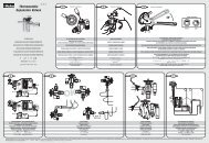
Wiring the <strong>Case</strong> <strong><strong>Control</strong>ler</strong><br />
Following the wiring diagram shown to the right, make the following<br />
connections. If not specified, connections are not polarized.<br />
If more than 5 amps are required for the fans, lights, or defrost heaters,<br />
the <strong>Case</strong> <strong><strong>Control</strong>ler</strong> relays can be used as the control signal for external<br />
relays. Use SPDT relays with the coil voltage matched to the supply voltage<br />
(120VAC or 230VAC) and a contact rating above the required current.<br />
4
Hardware Installation<br />
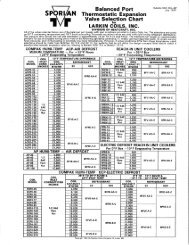
Wiring the <strong>Case</strong> <strong><strong>Control</strong>ler</strong> (cont.)<br />
In this case, the connections described below will be made to the external relay instead of the on-board relay.<br />
The <strong>Case</strong> <strong><strong>Control</strong>ler</strong>’s relays will be connected from the NO contact to the external relay as depicted on the<br />
following page.<br />
Note: See Technical Specifications (page 33) for relay ratings and output details.<br />
• Connect the fan to Relay #1.<br />
Connect L1 to the relay COM<br />
terminal. Connect L2 to one<br />
terminal on the fan. Connect<br />
an additional wire from the<br />
relay NC terminal to the other<br />
terminal on the fan.<br />
• Connect the defrost element<br />
to Relay #2. Connect L1 to the<br />
relay COM terminal. Connect<br />
L2 to one terminal on the<br />
defrost element. Connect<br />
an additional wire from the<br />
relay NO terminal to the other<br />
terminal on the defrost element.<br />
• Connect the lighting to Relay<br />
#3. Connect L1 to the relay<br />
COM terminal. Connect L2<br />
to one terminal on the lights.<br />
Connect an additional wire<br />
from the relay NC terminal to<br />
the other terminal on the lights.<br />
• Connect the network cable to<br />
the “Network” terminals on the<br />
controller. Connect the other<br />
end to the network terminals<br />
on the nearest Micro Thermo<br />
controller.<br />
• Connect the pressure<br />
transducer cable to “Pevap.”<br />
The three colored wires must be<br />
connected as shown.<br />
• Connect the evaporator<br />
temperature sensor to “Tevap.”<br />
• Connect the air temperature (or<br />
control temperature)<br />
sensor to “Tair.”<br />
• Connect the defrost<br />
termination sensor to “Tdef.”<br />
• Connect the optional auxiliary<br />
input temperature sensor<br />
to “Taux.”<br />
• Connect the external antisweat<br />
relay to the “Antisw”<br />
connection.<br />
• Connect dry-contact or<br />
switch to digital inputs<br />
“DI1” and/or “DI2.”<br />
• Connect the stepper motor<br />
valve to the “Valve” terminals.<br />
The four colored wires must be<br />
connected as shown.<br />
F1<br />
F2<br />
F3<br />
F4<br />
120/240V Power<br />
L N Earth<br />
FAN ELEC. DEFROST LIGHTING<br />
COM<br />
NO COM NC NO COM NC<br />
NO NC<br />
NETWORK RS485 DC OUT<br />
A B A B 26V Gnd<br />
P evap T evap T air T def T aux Di1 Di2 Antisw Valve<br />
5V S Gnd + - + - + - 2 3 1 4<br />
PWR<br />
PWR<br />
PWR<br />
120/240V<br />
Power<br />
Fan<br />
Electric Defrost<br />
Observe all local electrical codes.<br />
Use caution when working around<br />
high voltage components.<br />
Lighting<br />
Network<br />
Pressure Transducer<br />
NET<br />
RED<br />
WHITE<br />
P/N 023-0076 (Blue)<br />
Temperature Sensor (T° COIL)<br />
BLACK<br />
SHIELD<br />
BLACK<br />
WHITE<br />
GREEN<br />
RED<br />
Switch<br />
P/N 023-0072 (Orange)<br />
Temperature Sensor (T° DEF)<br />
P/N 023-0073 (Green)<br />
Temperature Sensor (T° AIR)<br />
SER or SEI<br />
Typical<br />
Stepper<br />
Motor Valve<br />
5
2<br />
Hardware Installation/Configuring the Defrost Scheduler From Alliance<br />
Installing the <strong>Case</strong> <strong><strong>Control</strong>ler</strong><br />
Wiring the <strong>Case</strong> <strong><strong>Control</strong>ler</strong> (cont.)<br />
When routing wires, please<br />
follow good wiring practices to<br />
avoid undesired interference<br />
on the network cable. High<br />
voltage wires should be routed<br />
at least 12” away from the<br />
communication cable, and<br />
the two should never be run<br />
through the same conduit. If a<br />
communication cable needs<br />
to cross a high voltage cable,<br />
make sure the two wires NO COMcross<br />
NC<br />
and are secured perpendicular<br />
to each other to reduce<br />
L1<br />
noise.<br />
Finally, connect the L2 120/240V<br />
to the power input’s removable<br />
NO COM<br />
L1<br />
L2<br />
terminal connector, and plug in<br />
to the board. Make sure leads<br />
are connected as shown.<br />
NC<br />
NO COM<br />
NC<br />
After all connections are made<br />
and the protective<br />
L1<br />
covers of the<br />
controller are L2 installed, apply<br />
power to the controller.<br />
Antisw<br />
Solid State Relay<br />
On-Board Relay Connections<br />
FANS LIGHTS DEFROST<br />
HEATERS<br />
External Relay Connections<br />
NO COM<br />
NC<br />
NO COM<br />
NC<br />
NO COM<br />
NC<br />
NO COM<br />
NC<br />
NO COM<br />
NC<br />
NO COM<br />
NC<br />
Tdef<br />
mperature Sensor<br />
ount per Manufacturer’s<br />
pecifications (optional)<br />
L1<br />
L2<br />
L1<br />
L2<br />
L1<br />
L2<br />
L1<br />
L2<br />
COM<br />
L1<br />
L2<br />
COM<br />
L1<br />
L2<br />
COM<br />
FANS LIGHTS DEFROST<br />
HEATERS<br />
NO NC<br />
NO NC<br />
NO NC<br />
V<br />
lation, are not shown.<br />
NO COM<br />
Mounting / Wiring the MT-504 Board<br />
L1<br />
NC<br />
The MT-504 control COM board should COM be mounted COM in an electrical panel, and can be located anywhere on the<br />
L2<br />
L2<br />
L2<br />
LonWorks® network.<br />
NO NC<br />
Connect the 18AWG network cable to the network terminals on the controller. The connections are not polarized.<br />
Connect the other end of the cable to the network terminal on another controller in the electrical panel.<br />
FANS<br />
LIGHTS<br />
DEFROST<br />
Connect 24VAC to the power input’s removable terminal block, and plug in to the board. After all connections are made,<br />
HEATERS<br />
apply power to the controller.<br />
Configuring the Defrost Scheduler From Alliance<br />
Getting Started<br />
NO COM<br />
In order to begin the software<br />
setup, the installer will need<br />
proper credentials to access the<br />
Configuration Mode in Alliance.<br />
© 2013 Parker Hannifin Corporation<br />
The DTSecCool installation<br />
requires setting up a ‘Node’ to<br />
program the controller, and a<br />
‘Plug-In’ to configure the settings<br />
used by the controller.<br />
After logging into Alliance, select<br />
the Refrigeration System and<br />
Configuration Mode. Select the<br />
L1<br />
NC<br />
NO NC<br />
L1<br />
NO COM<br />
NC<br />
NO NC<br />
FANS<br />
appropriate view, based upon<br />
the location of the DTSecCool<br />
node. Click-and-Drag the “Node”<br />
component from the list and<br />
drop it in the desired location on<br />
the active view. The icon can be<br />
moved at any time by holding<br />
the “CTRL” key and dragging the<br />
node to the new desired location.<br />
In the “Pick Node Type and<br />
Model” dialog box, select the<br />
communications channel that<br />
the node is connected to. For<br />
LIGHTS<br />
DEFROST<br />
HEATERS<br />
node type, select “Custom Node.”<br />
For manufacturer, select “Micro<br />
Thermo.” And for model, select<br />
“Dual Temp Sec Cool V7.0.”<br />
6
Configuring the Defrost Scheduler From Alliance<br />
Installing the Node:<br />
Click on the new node icon. On<br />
the Details tab, the node can be<br />
renamed if desired. To install the<br />
program on the controller, select<br />
the “Commands/Status” tab and<br />
click the “Install” button. A second<br />
window will appear. Alliance<br />
now requires the unique network<br />
identification number (known as<br />
Neuron ID) for the controller that<br />
is being installed.<br />
By default, Alliance waits for the<br />
controller to transmit its own<br />
Neuron ID. This is accomplished<br />
by pressing the Service button<br />
on the board. Alternatively, the<br />
installer can choose to manually<br />
enter the 12-digit, alpha-numeric<br />
ID and then continue by pressing<br />
“OK.” The Neuron ID can be<br />
found on the identification sticker<br />
adhered to the controller.<br />
Alliance is now installing the<br />
node. This may take several minutes.<br />
Once complete, click the<br />
“OK” button on the node window<br />
to return the Alliance main view.<br />
If prompted, click “Yes” to save<br />
changes.<br />
Micro Thermo recommends<br />
using the Service Button<br />
method. This eliminates<br />
the possibility of an input<br />
error and confirms network<br />
communication, both of<br />
which may be difficult to<br />
diagnose later.<br />
Creating the Plug-In<br />
With the node created and<br />
installed, an Alliance plug-in<br />
must be configured. Click-and-<br />
Drag the “Plug-In” component<br />
and drop it adjacent to the newly<br />
created node. In the “Choose<br />
a plug-in type” box, select the<br />
“Dual Temp Secondary Cooling”<br />
plug-in, version “6.1,” and select<br />
the name of the recently created<br />
node from the Node Ident<br />
drop-down box. Change the<br />
Identification field to a unique,<br />
easy to understand name.<br />
7
2<br />
Configuring the Defrost Scheduler From Alliance<br />
Installing the <strong>Case</strong> <strong><strong>Control</strong>ler</strong><br />
Configuring Defrost Schedules (cont.)<br />
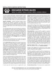
The DTSecCool plug-in is now created. Open the plug-in and go to the<br />
Configuration tab. Each DTSecCool node can support up to four circuits<br />
with defrost schedules. For each circuit to be controlled, complete the<br />
following:<br />
• Select the “Use Circuit” checkbox<br />
• Give the circuit a unique, easily identifiable name<br />
• Select the Defrost Type: Hot Gas, Electric, or Off Time<br />
• Since the <strong>Case</strong> <strong><strong>Control</strong>ler</strong>s will be controlling individual fans,<br />
select “” for Fan Relay.<br />
• Select the output for the Defrost Relay: select “” if the <strong>Case</strong><br />
<strong><strong>Control</strong>ler</strong> will be controlling an individual element, or the appropriate<br />
relay if the MT-504 controller will be controlling<br />
defrost for the circuit.<br />
8
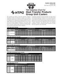
Configuring the Defrost Scheduler From Alliance<br />
(cont.)<br />
Next, set the defrost schedule for each circuit. Select the<br />
Defrost tab, and click the “Timing” button next to the first<br />
circuit. The Defrost Timing Window appears. Set the defrost<br />
parameters as desired for the circuit, and press “OK.”<br />
Repeat the Defrost Timing configuration for each circuit.<br />
The defrost time can be changed for each circuit<br />
individually to avoid simultaneous defrosts.<br />
The red/gray boxes on the time graph indicate when each<br />
circuit will be in defrost. Click-and-Drag any of the red/<br />
gray boxes to adjust the defrost time earlier<br />
or later. If the “Distributed evenly over 24h” option was<br />
selected in the previous step, all defrosts for a given<br />
circuit will move together to maintain spacing.<br />
After the timing has been set up, the DTSecCool set up<br />
is complete. Press “OK” to save the settings and update<br />
the controller.<br />
9
2<br />
Configuring the <strong>Case</strong> <strong><strong>Control</strong>ler</strong> From MT Alliance<br />
Installing the <strong>Case</strong> <strong><strong>Control</strong>ler</strong><br />
Configuring the <strong>Case</strong> <strong><strong>Control</strong>ler</strong> From MT Alliance<br />
Getting Started<br />
In order to begin the software<br />
setup, the installer will need<br />
proper credentials to access the<br />
Configuration Mode in Alliance.<br />
Click-and-Drag the “<strong>Case</strong> Ctrl”<br />
component from the list and drop it<br />
in the desired location on the active<br />
view. The icon can be moved within<br />
the current view at any time. While<br />
holding the “CTRL” key, click-anddrag<br />
the <strong>Case</strong> <strong><strong>Control</strong>ler</strong> icon to the<br />
new desired location.<br />
Click on the new <strong>Case</strong> <strong><strong>Control</strong>ler</strong><br />
icon to begin the installation<br />
process. The <strong>Case</strong> <strong><strong>Control</strong>ler</strong><br />
Configuration Window, shown<br />
below, will open.<br />
The <strong>Case</strong> <strong><strong>Control</strong>ler</strong> Configuration Window before creating the <strong>Case</strong> <strong><strong>Control</strong>ler</strong> Lineup.<br />
10
Configuring the <strong>Case</strong> <strong><strong>Control</strong>ler</strong> From MT Alliance<br />
Creating a Lineup<br />
Before configuring, Alliance must<br />
first create the nodes that will be<br />
installed to the <strong>Case</strong> <strong><strong>Control</strong>ler</strong>.<br />
To simplify installation and future<br />
configuration changes, multiple<br />
<strong>Case</strong> <strong><strong>Control</strong>ler</strong>s can be created<br />
as a Lineup.<br />
A lineup can include up to 16<br />
<strong>Case</strong> <strong><strong>Control</strong>ler</strong>s, which will share<br />
many or all configuration parameters.<br />
This feature streamlines<br />
installation and reduces time on<br />
future modifications. Configurations<br />
made to one controller will<br />
be automatically propagated to<br />
all controllers in the lineup.<br />
Give the <strong>Case</strong> <strong><strong>Control</strong>ler</strong> and<br />
Lineup unique names in the<br />
“Identification” and “Lineup<br />
Identification” fields, respectively.<br />
Select the Lineup Size.<br />
To create the node(s) that will<br />
later be downloaded to the <strong>Case</strong><br />
<strong><strong>Control</strong>ler</strong>(s), click “Create CCtrl.”<br />
A new window will appear asking<br />
to specify the network channel.<br />
After clicking OK, Alliance will<br />
create additional <strong>Case</strong> <strong><strong>Control</strong>ler</strong><br />
icons according the lineup size<br />
specified, and the Configuration<br />
window will expand with additional<br />
parameters.<br />
Shared Parameters<br />
can be in one of<br />
three states:<br />
Permanently Shared<br />
Some basic settings are<br />
permanently shared and cannot<br />
be disconnected. Changes made to<br />
any <strong>Case</strong> <strong><strong>Control</strong>ler</strong> in the<br />
lineup will always be applied to the<br />
entire lineup. These settings include:<br />
network configuration,<br />
circuit specifications, lighting<br />
settings, and others.<br />
Currently Shared<br />
The majority of settings are initially<br />
shared throughout the lineup,<br />
but can be disconnected at any<br />
time. Changes made to any <strong>Case</strong><br />
<strong><strong>Control</strong>ler</strong> in the lineup will be<br />
applied to the entire lineup. Single<br />
clicking on this icon offers two<br />
options. Clicking “Highlight group<br />
parameters” highlights all of the<br />
parameters that will be affected if<br />
this group is disconnected. Clicking<br />
“Shared” will disconnect the group<br />
of parameters within the lineup.<br />
The <strong>Case</strong> <strong><strong>Control</strong>ler</strong> Configuration Window after creating the <strong>Case</strong><br />
<strong><strong>Control</strong>ler</strong> Lineup.<br />
Disconnected<br />
Settings are no longer shared<br />
across the lineup. Only nonpermanently<br />
shared parameters<br />
can be disconnected; and once<br />
disconnected, these settings<br />
cannot be shared again. The<br />
current values stored at the time<br />
of disconnecting will remain saved.<br />
However, all future changes made<br />
to a <strong>Case</strong> <strong><strong>Control</strong>ler</strong> will affect only<br />
that specific device.<br />
11
2<br />
Configuring the <strong>Case</strong> <strong><strong>Control</strong>ler</strong> From MT Alliance<br />
Installing the <strong>Case</strong> <strong><strong>Control</strong>ler</strong><br />
Programming the<br />
<strong>Case</strong> <strong><strong>Control</strong>ler</strong><br />
occurs in two steps:<br />
1. Installing the Node<br />
2. Sending Configuration<br />
Parameters<br />
(Abbreviated CPs)<br />
Installing the Node:<br />
aThis step can be completed at any point before, during, or after the<br />
setpoint parameters are configured.<br />
aThese steps must be repeated for each individual <strong>Case</strong> <strong><strong>Control</strong>ler</strong><br />
being added to the system.<br />
Installing the node entails several internal processes that setup both<br />
Alliance and the new controller for proper operation, including<br />
transmitting the <strong>Case</strong> <strong><strong>Control</strong>ler</strong> program to the hardware. This occurs<br />
one time during initial setup, and must be completed for each <strong>Case</strong><br />
<strong><strong>Control</strong>ler</strong> added to the system. Configuration parameters (discussed<br />
later in this section) assign the controller’s inputs and outputs, set<br />
system information, and update all setpoints. These parameters can be<br />
either shared among multiple controllers or configured independently,<br />
and are automatically retransmitted whenever settings are saved in<br />
Alliance.<br />
To install the <strong>Case</strong> <strong><strong>Control</strong>ler</strong> program to the controller, click on the<br />
highlighted “Install” button. After the new window appears, select the<br />
“Commands/Status” tab. Next, click the “Install” button. A third window<br />
will appear. Alliance now requires the unique network identification<br />
number (known as Neuron ID) for the <strong>Case</strong> <strong><strong>Control</strong>ler</strong> that is being<br />
installed.<br />
By default, Alliance waits for the <strong>Case</strong><br />
<strong><strong>Control</strong>ler</strong> to transmit its own Neuron<br />
ID. This is accomplished by pressing<br />
the Service button on the controller.<br />
Alternatively, the installer can choose<br />
to manually enter the 12-digit, alphanumeric<br />
ID and then continue by<br />
pressing “OK.” The Neuron ID can be<br />
found by removing the <strong>Case</strong> <strong><strong>Control</strong>ler</strong>’s<br />
cover and locating the identification<br />
sticker on the raised printed circuit board.<br />
Micro Thermo<br />
recommends using the<br />
Service Button method.<br />
This eliminates the possibility<br />
of an input error<br />
and confirms network<br />
communication, both of<br />
which may be difficult<br />
to diagnose later.<br />
Alliance is now installing the node. Once complete, click the “OK” button<br />
on the second window to return to the <strong>Case</strong> <strong><strong>Control</strong>ler</strong> configuration<br />
window.<br />
Reminder: You must repeat the previous steps to install<br />
the node on each individual <strong>Case</strong> <strong><strong>Control</strong>ler</strong> being added<br />
to the system.<br />
12
Configuring the <strong>Case</strong> <strong><strong>Control</strong>ler</strong> From MT Alliance<br />
Configuration<br />
Parameters<br />
Upon initial setup, the <strong>Case</strong><br />
<strong><strong>Control</strong>ler</strong> starts in “Vacuum<br />
Mode.” The controller does<br />
not begin normal operation<br />
until the installer activates<br />
“Refrigeration Mode.”<br />
The <strong>Case</strong> <strong><strong>Control</strong>ler</strong> or lineup<br />
parameters can now be modified<br />
to achieve the desired operation.<br />
Across the top, the Configuration<br />
Window is divided into 10 tabs.<br />
The contents of the first five<br />
tabs are detailed below. The<br />
remaining tabs are explained in<br />
more detail in Section 3 – <strong>Case</strong><br />
<strong>Control</strong> Operation.<br />
Many of the parameters available will only be used for advanced configurations or to achieve unique behavior<br />
on some systems. Common parameters used during installation are listed below. For a complete list of<br />
parameter definitions, see Appendix A.<br />
Alliance highlights certain fields in yellow to indicate key settings that need to be set (or confirmed) before<br />
operation can begin. A tab marked by a yellow diamond indicates the presence of highlighted fields. Other<br />
fields may be grayed-out, indicating values which cannot be changed at this time.<br />
The Configuration Window is dynamic. As certain selections are made, other options will become available<br />
or be removed from the configuration window.<br />
System Tab<br />
The System tab provides an overview of the refrigeration system to which the <strong>Case</strong> <strong><strong>Control</strong>ler</strong> is connected.<br />
Many settings are built into the system and cannot be changed.<br />
Load Type<br />
Specify the type of case being controlled; this determines certain preset parameter control values and may<br />
disable parameters that do not apply.<br />
Circuit ID<br />
Specify the circuit for the <strong>Case</strong> <strong><strong>Control</strong>ler</strong>; this configures some shared network data and determines the<br />
defrost scheme. To add/edit circuits in the dropdown list, see “Configuring DTSecCool Node for Defrosts.”<br />
Refrigerant<br />
Specify the refrigerant being used.<br />
13
2<br />
Configuring the <strong>Case</strong> <strong><strong>Control</strong>ler</strong> From MT Alliance<br />
Installing the <strong>Case</strong> <strong><strong>Control</strong>ler</strong><br />
Config Tab<br />
The Config tab provides detailed settings for how the <strong>Case</strong> <strong><strong>Control</strong>ler</strong><br />
is being used. Many of these settings impact other parameters and setpoints<br />
later in the configuration process.<br />
If any changes are made, all settings on Inputs / Outputs tab and<br />
<strong>Control</strong> tab must verified.<br />
Process <strong>Control</strong> Type<br />
Specify the control scheme desired:<br />
Temperature <strong>Control</strong> with Superheat Limit controls the expansion<br />
valve to optimize case temperature, as long as the superheat is at<br />
an acceptable level. If superheat falls to the specified threshold,<br />
the controller will begin closing the valve. Once superheat returns<br />
above the threshold, the controller will resume maintaining case<br />
temperature.<br />
Superheat <strong>Control</strong> Only controls the expansion valve to maintain the<br />
specified superheat.<br />
Temperature <strong>Control</strong> Only controls the expansion valve to maintain<br />
a specified case temperature.<br />
End Defrost Source<br />
Specify the temperature input that will trigger the controller to end<br />
defrost. By default, the controller uses the dedicated defrost termination<br />
sensor.<br />
14
Configuring the <strong>Case</strong> <strong><strong>Control</strong>ler</strong> From MT Alliance<br />
Config Tab (cont.)<br />
Light & Curtains<br />
Specify whether the lighting<br />
schedule will be configured on<br />
the controller (locally), over the<br />
network from the main scheduler<br />
(remotely), or neither. If selecting<br />
Remote, specify the source and<br />
schedule the <strong>Case</strong> <strong><strong>Control</strong>ler</strong><br />
should use.<br />
Anti-Sweat<br />
If anti-sweat heaters are present,<br />
specify whether the <strong>Case</strong><br />
<strong><strong>Control</strong>ler</strong> will be controlling<br />
based upon a constant pulse<br />
method or based upon the dew<br />
point provided from the Anti-<br />
Sweat board.<br />
Dual Use<br />
If the case is used at two different<br />
temperatures, a switch can be<br />
used to quickly change between<br />
two configured setpoints. Select<br />
“Dual Temp. Unit” and specify<br />
the DUS source that will select the<br />
temperature:<br />
Software Switch will enable<br />
an icon on the Process<br />
tab for switching between<br />
temperatures.<br />
Local Switch will select<br />
temperature based upon the<br />
position of a physical switch<br />
connected to one of the digital<br />
inputs.<br />
Remote Switch will select<br />
temperature based upon<br />
a signal from another device on<br />
the network.<br />
Door Ajar<br />
If a door ajar switch is present,<br />
select the type of switch (local<br />
or remote) and then specify the<br />
location where the <strong>Case</strong> <strong><strong>Control</strong>ler</strong><br />
should monitor.<br />
Inputs / Outputs Tab<br />
The Inputs / Outputs tab<br />
provides the controller with<br />
the necessary details to<br />
accurately interact with all<br />
sensors, switches, network<br />
connections, and the<br />
electric valve.<br />
Evaporator Pressure<br />
Select the Manufacturer and<br />
Model for the pressure transducer<br />
installed on the suction line.<br />
Temperature Sensors<br />
Select the Manufacturer and<br />
Models for each temperature<br />
sensor listed; select “None” for<br />
any input that is not connected.<br />
15
2<br />
Configuring the <strong>Case</strong> <strong><strong>Control</strong>ler</strong> From MT Alliance<br />
Installing the <strong>Case</strong> <strong><strong>Control</strong>ler</strong><br />
Inputs / Outputs Tab (cont.)<br />
Digital Inputs<br />
Verify the digital input settings (or absence) based upon selections made<br />
on the Config tab.<br />
Outputs<br />
Select the valve output, Manufacturer, and Model for the connected<br />
valve from the drop-down lists.<br />
Environmental Variables<br />
The <strong>Case</strong> <strong><strong>Control</strong>ler</strong> factors in environmental/system parameters<br />
to optimize valve control. Select the network locations for any/<br />
all of the four variables (if present). Once the first <strong>Case</strong> <strong><strong>Control</strong>ler</strong>’s<br />
Environmental Variables are configured, this group of settings will be<br />
shared across the network. All future <strong>Case</strong> <strong><strong>Control</strong>ler</strong> setups can be<br />
expedited by selecting the grouped environmental variable, and these<br />
settings will automatically be replicated.<br />
Alarm Settings Tab<br />
Alarm settings can be fully customized to meet the operational needs of<br />
the case and its contents. A list of commonly used, pre-set alarm settings<br />
are available to use as a starting point. To begin, click the “Pick Alarm<br />
Settings” button. Choose one that closely meets the needs for this <strong>Case</strong><br />
<strong><strong>Control</strong>ler</strong>; or if none apply, press “Cancel” to return to the previous<br />
screen.<br />
16
Configuring the <strong>Case</strong> <strong><strong>Control</strong>ler</strong> From MT Alliance<br />
Alarm Settings Tab (cont.)<br />
Alarm Settings<br />
Specify the case temperature set point in the Optimal Temperature field.<br />
Set 1 Settings<br />
Specify the operation of the primary alarm:<br />
High/Low Limits: the temperature thresholds which constitute an<br />
alarm condition.<br />
Set Time: the time delay during which the temperature must remain<br />
outside of the high/low limit before the alarm signal is activated.<br />
Recall Time: if an alarm is Acknowledged in Alliance but the alarm<br />
condition persists, the alarm signal will be reactivated after the delay<br />
specified by the recall time. This feature ensures alarm conditions are<br />
not dismissed or forgotten without being resolved.<br />
Priority Level: the severity indicated in the alarm message.<br />
Temperature alarms should be considered high priority.<br />
Relay: the external output relay to activate when the alarm is<br />
triggered, if desired.<br />
Set 2 Settings<br />
Select the “Set 2 Active” checkbox to activate the secondary alarm.<br />
Follow the same convention as Set 1 Settings.<br />
Cumulative Alarm<br />
To activate the cumulative alarm, select which alarm set to use as<br />
boundary threshold. Next, specify the time outside of range that will<br />
activate the alarm and the cumulative period over which to monitor.<br />
Note: If the <strong>Case</strong> <strong><strong>Control</strong>ler</strong> is configured for Dual Temperature,<br />
then Alarm Set 1 is the alarm thresholds for Temperature Set 1;<br />
Alarm Set 2 is the alarm thresholds for Temperature Set 2; and<br />
the Cumulative alarm is disabled.<br />
<strong>Control</strong> Tab<br />
The <strong>Control</strong> tab provides settings that precisely configure the controller<br />
operation. Default values have been calculated for optimal control in<br />
most system configurations. For most installations, the “Basic View”<br />
will provide all of the necessary settings. Should more control options<br />
become needed, select the “Advanced View” button.<br />
The <strong>Control</strong> tab is divided into additional tabs, itemized down the left<br />
side of the window. The following parameters should be configured or<br />
verified to meet the system needs.<br />
The <strong>Case</strong> <strong><strong>Control</strong>ler</strong><br />
provides three<br />
alarm options<br />
for each case:<br />
Set 1 - Primary<br />
Set 1 is the primary alarm setting,<br />
usually used to alert when the case<br />
reaches a temperature<br />
at which food loss/damage<br />
is imminent.<br />
Set 2 - Secondary<br />
Set 2 allows for a second<br />
temperature range to be set and<br />
is usually used to alert when the<br />
case reaches a temperature that will<br />
decrease product quality or shelf life.<br />
Set 2 is often set with a narrower<br />
high/low limit, but a longer delay than<br />
Set 1.<br />
Cumulative Alarm<br />
On occasion, the case temperature<br />
may exceed the alarm boundaries<br />
(e.g., during defrost). Delays are built<br />
in to most refrigeration controllers<br />
to avoid nuisance alarms, while still<br />
ensuring that temperatures return to<br />
normal within an acceptable time.<br />
However, frequent temperature<br />
variations can still have a negative<br />
impact on the product quality over<br />
time. Micro Thermo’s Cumulative<br />
Alarm is based on the HACCP<br />
standard for food safety and tracks<br />
the total time that a case temperature<br />
exceeds the alarm boundaries.<br />
17
2<br />
Configuring the <strong>Case</strong> <strong><strong>Control</strong>ler</strong> From MT Alliance<br />
Installing the <strong>Case</strong> <strong><strong>Control</strong>ler</strong><br />
<strong>Control</strong> Tab (cont.)<br />
Valve<br />
Base %Open is the approximate position of the valve under steady<br />
state condition with a normal load. This value is used in many<br />
calculations. Improving the accuracy of this value will improve<br />
the efficiency of the control scheme and reduce valve hunting.<br />
Max %Open is the maximum position the controller will place the<br />
valve. Specify the position as a multiple of Base %Open, and confirm<br />
the percentage value.<br />
Superheat<br />
While controlling case temperature, the controller disregards the current<br />
superheat as long as it remains above the “Threshold.”<br />
Cut Off is the minimum allowable superheat. At this temperature, the<br />
valve will be positioned at the minimum valve position, in order to<br />
protect the compressor.<br />
18
2<br />
Configuring the <strong>Case</strong> <strong><strong>Control</strong>ler</strong> From MT Alliance<br />
<strong>Control</strong> Tab (cont.)<br />
Band is the temperature range over which the controller will<br />
progressively close the valve, in attempt to raise the superheat. The<br />
“Threshold” value is the sum of the cut off temperature and the band.<br />
Pulldown<br />
Initial %Open specifies the initial placement of the valve when<br />
refrigeration resumes after defrost. The standard control scheme is<br />
ignored until temperature returns to an acceptable range.<br />
Temperature <strong>Control</strong><br />
Allows for advanced configuration of temperature response. PID settings<br />
should only be changed by experienced professionals.<br />
Minimum %Open located in the “Advanced View,” is the minimum<br />
position the controller will place the valve.<br />
Defrost<br />
%Open in Defrost specifies the position of the valve during defrost.<br />
End Defrost Temperature specifies the temperature at which defrost<br />
will be ended for this controller. This setting will not terminate defrost<br />
on any other <strong>Case</strong> <strong><strong>Control</strong>ler</strong>.<br />
%Open on End Defrost specifies the position of the valve after defrost.<br />
The controller will hold this position while it awaits signal that all<br />
other controllers on the circuit have completed defrost.<br />
%Open in Pumpdown specifies the valve position during pumpdown.<br />
%Open in Drip specifies the valve position after the circuit has<br />
completed defrost, before refrigeration mode is activated.<br />
Door Ajar<br />
Allows the controller to stop refrigeration when the door ajar switch is<br />
activated.<br />
%Open on Door Ajar specifies the position of the valve while the door<br />
ajar switch is activated.<br />
Fans<br />
Stop Fans on Door Ajar specifies when to stop fans if the door ajar<br />
switch is activated.<br />
Stop Fans on Defrost intelligently starts/stops the evaporator fan to<br />
maximize the residual cooling effect of refrigerant in the evaporator.<br />
19
2<br />
Configuring<br />
the <strong>Case</strong> <strong><strong>Control</strong>ler</strong> From MT Alliance<br />
Installing the <strong>Case</strong> <strong><strong>Control</strong>ler</strong><br />
<strong>Control</strong> Tab (cont.)<br />
Stop Fans on Defrost (cont.)<br />
The controller will leave the fans running until the case temperature<br />
begins to rise (or for the maximum duration specified by Timeout).<br />
The <strong><strong>Control</strong>ler</strong> will leave the fans off after defrost until the evaporator<br />
temperature has been pulled down (or for the maximum duration<br />
specified by Timeout).<br />
Lighting<br />
Specifies a basic lighting schedule for this case, if Local was selected on<br />
the Config tab.<br />
Anti-Sweat<br />
Specifies the function of the Anti-Sweat pulsed output.<br />
Default Anti-Sweat specifies the percentage of time the heaters will be<br />
on, if Constant Pulse Method was selected on the Config Tab.<br />
Saving Changes<br />
At any point during the configuration, the current progress can be saved<br />
and resumed at a later time. Press the “Apply” button to save without<br />
closing the current window; press the “OK” button to save<br />
and exit the configuration. Clicking either button will cause the<br />
Configuration Parameters to download to the controller. This may<br />
take a few minutes.<br />
20
Configuring the <strong>Case</strong> <strong><strong>Control</strong>ler</strong> From MT Alliance<br />
Starting Refrigeration Mode<br />
After all settings have been configured, the <strong>Case</strong> <strong><strong>Control</strong>ler</strong> is ready for<br />
operation. However, the controller will remain in Vacuum Mode until<br />
activated.<br />
If the steps for “Installing the Node” were skipped earlier, this must be<br />
completed before activating Refrigeration Mode.<br />
When the system is ready to be started and the controllers are ready to begin<br />
Refrigeration mode, open any <strong>Case</strong> <strong><strong>Control</strong>ler</strong> Configuration Window. On the<br />
System tab, select the blue “Vacuum / Refrig. Mode” button. A second dialog<br />
window will open with a list of <strong>Case</strong> <strong><strong>Control</strong>ler</strong>s on the network. Select the <strong>Case</strong><br />
<strong><strong>Control</strong>ler</strong>s on the system that are still in Vacuum Mode and are ready to be<br />
activated. Click the Refrigeration Mode button to begin normal operation.<br />
21
3<br />
Overview / <strong><strong>Control</strong>ler</strong> Status<br />
<strong>Case</strong> <strong>Control</strong> Operation<br />
Overview<br />
The <strong>Case</strong> <strong><strong>Control</strong>ler</strong> and Alliance<br />
software offer historical and<br />
comprehensive real-time<br />
information about the device’s<br />
operation. Alliance’s graphical<br />
user interface allows an<br />
approved user, from technician<br />
to corporate executive, access to<br />
the information they need to keep<br />
equipment running correctly and<br />
efficiently. The controller also<br />
features ten LED indicators for a<br />
visual status update.<br />
<strong><strong>Control</strong>ler</strong> Status<br />
Status Key:<br />
RS485 Rx/Tx<br />
LON Rx/Tx<br />
Off<br />
Unused at this time.<br />
On<br />
Flashing<br />
Indicates activity on the LonWorks network; the controller<br />
is either sending or receiving data.<br />
Status<br />
During normal operation, the status indicator will flash<br />
twice followed by a one second delay.<br />
In wink mode, the status indicator will flash quickly. After<br />
one minute, wink mode will automatically end, and the<br />
indicator will return to normal.<br />
Air Temp<br />
The <strong>Control</strong> Temperature input is set to ,<br />
and the controller is not monitoring this input.<br />
<strong>Case</strong> temperature is currently 4.5° (or more)<br />
above set point.*<br />
<strong>Case</strong> temperature is currently between<br />
2.5° and 4.5° above set point.*<br />
<strong>Case</strong> temperature is currently within 2.5° of set point.*<br />
<strong>Case</strong> temperature is currently 2.5° (or more)<br />
below set point.*<br />
*These temperature thresholds can be changed in <strong>Case</strong> <strong><strong>Control</strong>ler</strong><br />
plug-in by clicking the “Indicator” button on the Alarm tab.<br />
22
<strong><strong>Control</strong>ler</strong> Status<br />
Temp Alarm<br />
Other Alarm<br />
Valve<br />
No alarm present.<br />
The <strong>Case</strong> Temperature alarm is active. This light will remain<br />
lit until the alarm is acknowledged in Alliance.<br />
No alarm present.<br />
An alarm, other than case temperature, is currently active.<br />
This light will remain lit until the alarm is acknowledged in<br />
Alliance.<br />
The valve is not connected, or is connected incorrectly.<br />
The valve is connected and idle.<br />
Defrost<br />
Fan<br />
Lights<br />
Anti-Sweat<br />
The controller is currently moving the valve.<br />
The controller is in refrigeration mode.<br />
The controller is waiting for pumpdown<br />
or drip time to complete.<br />
The controller is in defrost mode.<br />
The fan is currently off.<br />
The fan is currently on.<br />
The lights are currently off.<br />
The lights are currently on.<br />
The Anti-Sweat output is off.<br />
The Anti-Sweat output is on.<br />
23
3<br />
MT Alliance<br />
<strong>Case</strong> <strong>Control</strong> Operation<br />
MT Alliance<br />
The three modes in the<br />
Alliance software provide<br />
different levels of access<br />
to controller data and<br />
configuration.<br />
After logging in to the Alliance software, all users<br />
will have access to the Overview mode. Based<br />
on assigned credentials, some users will have<br />
access to the Maintenance mode. And a few<br />
select users will have the highest level privileges<br />
with Configuration mode.<br />
After logging in to the Alliance software, locate<br />
the <strong>Case</strong> <strong><strong>Control</strong>ler</strong> on the building floor plan<br />
and select the icon. The <strong>Case</strong> <strong><strong>Control</strong>ler</strong> plug-in<br />
window will open. Depending on the current<br />
mode, some tabs will not be accessible.<br />
In Overview mode:<br />
The user will be able to view alarm settings, view<br />
details of current state of the controller, view<br />
historical graphs, and view the change log for<br />
the controller.<br />
In Maintenance mode:<br />
The plug-in will show an additional five tabs that<br />
allow the user to view configuration settings.<br />
The alarm settings can also be modified in<br />
Maintenance mode.<br />
In Configuration mode:<br />
All tabs will be shown and configuration<br />
parameters can be modified to customize the<br />
operation of the controller.<br />
24
MT Alliance<br />
Viewing Detailed Status<br />
Details of the controller’s operation can be viewed in any mode. After opening the <strong>Case</strong> <strong><strong>Control</strong>ler</strong> plug-in,<br />
select the Process tab.<br />
If the <strong>Case</strong> <strong><strong>Control</strong>ler</strong> is configured for Dual Temperature, the Setpoint section at the top will show both<br />
temperature setpoints. Further, if the temperature is selected by Software Switch, a light switch icon will<br />
be shown between the two setpoints. The position of the switch in the image indicates the current setpoint<br />
selected; clicking the icon will toggle between the two setpoints.<br />
If the bottom half of the window is blank, click the “More” button to expand the view. The Process tab shows<br />
all real-time data reported from the controller. This includes temperature set point, input readings (including<br />
door ajar and environmental variables, if present), all outputs, and system mode. Alliance incorporates<br />
a graphical display, representing the components of the system, in addition to the numerical readings:<br />
Lights<br />
The light bulb icon at the top is illuminated yellow when the lights are on; the yellow disappears when the<br />
lights are off.<br />
Door Ajar<br />
The door icon will show an open or closed door, to match the reading of the door ajar switch.<br />
Fans<br />
The fan blade icon spins while the fan is turned on, and remains stationary while the fan is off.<br />
25
3<br />
MT Alliance<br />
<strong>Case</strong> <strong>Control</strong> Operation<br />
Viewing Detailed Status (cont.)<br />
During normal operation, a green circle beside an input indicates the value is within the alarm limits and<br />
functioning as expected. If any values trigger an alarm, this icon will change to red and easily identify the<br />
source of the alarm. After acknowledging the alarm condition, the icon changes to yellow to indicate the<br />
recall period. After the recall time has passed, if no alarm is present, the icon will return to green. A blue icon<br />
indicates the alarm is temporarily disabled. This includes the superheat alarm automatically being disabled<br />
during defrost.<br />
Overriding Outputs<br />
From the Process tab, the user can manually override each of the<br />
outputs. Use caution when overriding outputs. If not done correctly,<br />
serious system damage can occur. Overriding outputs requires either<br />
Maintenance mode or Configuration mode be selected. Locate the<br />
button on the left edge of the Process tab to override a specific output.<br />
Clicking the button will open a new window. Activate the override from<br />
the drop down box and select the end time when the controller will<br />
resume normal operation. For EEV override, fill in the percent open to<br />
position the valve.<br />
Click Ok to close the window.<br />
Reminder: The override will not take effect until the settings are<br />
downloaded to the controller. Click Apply to activate the override.<br />
View / Modify Alarms<br />
From the Alarm tab, all alarm<br />
thresholds can be viewed. If<br />
Maintenance or Configuration<br />
mode is selected, these values<br />
can also be modified. For<br />
definitions of Set 1, Set 2, and<br />
Cumulative alarms, see the<br />
“Alarm Tab” section under<br />
Installation. To disable all<br />
alarms on the controller, select<br />
“Disable Alarm Permanently” or<br />
“Disable Alarm Temporarily.” Fill<br />
in the reason and the end time<br />
for the alarms to be automatically<br />
reactivated (for temporary).<br />
Individual alarms can be<br />
configured through the buttons<br />
along the right edge. To activate/<br />
deactivate, temporarily disable,<br />
and customize the settings, click<br />
on the button for the appropriate<br />
alarm. A new window will open.<br />
Fill in the fields, as desired.<br />
Use Alarm: permanently<br />
enable/disable the alarm.<br />
Set Time: the time delay<br />
during which the alarm<br />
condition must remain before<br />
the alarm signal is activated.<br />
Recall Time: if an alarm is<br />
Acknowledged in Alliance but<br />
the alarm condition persists, the<br />
alarm signal will be reactivated<br />
after the delay specified by<br />
the recall time. This feature<br />
ensures alarm conditions are not<br />
dismissed or forgotten without<br />
being resolved.<br />
Priority Level: the severity<br />
indicated in the alarm message.<br />
The superheat alarm should be<br />
considered high priority.<br />
Relay: the external output relay<br />
to activate when the alarm is<br />
triggered, if desired.<br />
Disable Alarms Temporarily:<br />
temporarily disable the alarm.<br />
The alarm will be automatically<br />
reactivated at the time specified.<br />
Provide a reason to be recorded in<br />
the controller’s log.<br />
The superheat alarm contains two<br />
additional parameters that specify<br />
when the alarm is activated. The<br />
superheat alarm is cumulative.<br />
The <strong>Case</strong> <strong><strong>Control</strong>ler</strong> keeps a “Time<br />
in Overflow” timer for the time<br />
superheat is below the low limit.<br />
Rising above the low limit will<br />
not “reset” the timer. Instead, the<br />
timer counts up while superheat<br />
is below the low limit and counts<br />
down while superheat is above<br />
the low limit. When “Time in<br />
26
MT Alliance<br />
View / Modify Alarms (cont.)<br />
Overflow” exceeds the set time,<br />
the alarm is activated.<br />
Low Limit: the superheat<br />
threshold that constitutes an<br />
alarm condition.<br />
Overflow Tolerance:<br />
Overflow tolerance is the rate at<br />
which time is subtracted from the<br />
alarm timer. For example: with<br />
the default 25%, every 4 seconds<br />
above the low limit decreases<br />
the timer by 1 second (25%). This<br />
value can be set between 1% and<br />
50%. The higher the value, the<br />
faster the alarm timer will reset;<br />
the lower the value, the slower<br />
the timer will reset.<br />
The Air Temp indicator on<br />
the <strong>Case</strong> <strong><strong>Control</strong>ler</strong> can be<br />
customized from the Alarm tab.<br />
Click the “Indicator LEDs” button.<br />
In the new window that opens, the<br />
thresholds for the color/flash pattern on<br />
the controller’s face can be set. Select<br />
the temperature error that causes the<br />
red LED to flash, indicating very high<br />
temperature; the temperature error that<br />
causes the red LED to stay lit, indicating<br />
high temperature; and the temperature<br />
error that causes the green LED to flash,<br />
indicating low temperature.<br />
View Historical Graphs<br />
The Graphs tab provides access to all historical data saved on the data logger. By default, Alliance shows the<br />
<strong>Control</strong> Temp graph, which includes the alarm thresholds in red and the optimal temperature in blue. Graphs can<br />
be viewed for Alarm Set 1, Alarm Set 2, or both simultaneously by selecting the desired option located to the right<br />
of the graph.<br />
27
3<br />
MT Alliance<br />
<strong>Case</strong> <strong>Control</strong> Operation<br />
View Historical Graphs (cont.)<br />
The graph will indicate in red the time when the alarm for this sensor was active. Also, if the Cumulative alarm<br />
is set, Alliance will highlight the graph where the temperature is outside of range.<br />
Using “Sensor” drop down box at<br />
the top, you can view the history<br />
for any other stored variable.<br />
The two drop down boxes<br />
below the graph can be used to<br />
adjust the vertical scale and the<br />
horizontal time frame of graph.<br />
The Graph Info along the right<br />
edge provides specific values for<br />
the point in time marked by the<br />
blue vertical line. This vertical<br />
line can be moved, either by<br />
clicking on another location on<br />
the graph or by dragging the<br />
gray slider above the graph. All<br />
events corresponding to the<br />
selected variable appear in the<br />
table below the graph. The log<br />
can be filtered or printed using<br />
the buttons along the ridge edge.<br />
New notes can also be added for<br />
future reference.<br />
Multiple variables can be<br />
viewed on side by side graphs,<br />
for instance to assist in system<br />
troubleshooting. First, click the<br />
“Trend Graphs” button near<br />
the top of the Graphs tab. In<br />
the new window, up to seven<br />
stored variables can be plotted<br />
separately, or combined onto one<br />
graph for easy viewing. Click the<br />
Ellipsis button beside the variable<br />
name to select a different variable,<br />
from any node connected to<br />
Alliance. Graphs can be added,<br />
removed, reordered on the screen,<br />
printed, and saved for quick<br />
viewing in the future.<br />
28
MT Alliance<br />
View Change Log<br />
The Alliance software records every<br />
change made to any setting in every<br />
plug-in. This information can be<br />
particularly valuable later when<br />
diagnosing a recent problem or to<br />
find details of a change to the system.<br />
The log for each device is saved<br />
separately, and can be accessed<br />
through the plug-in window. From<br />
any mode, simply select the Log tab<br />
at the top. The table includes every<br />
change made to this <strong>Case</strong> <strong><strong>Control</strong>ler</strong><br />
since its installation.<br />
To filter the list, simply select a start<br />
and end date and the type of change<br />
made from the options below the<br />
table. Notes can be added to the log<br />
for future reference by using the Add<br />
button. And the Print Log button<br />
allows the user to print the filtered<br />
list, if desired.<br />
When Maintenance mode is selected,<br />
the <strong>Case</strong> <strong><strong>Control</strong>ler</strong> plug-in window<br />
allows access to the System tab,<br />
Config tab, Inputs/Outputs tab,<br />
<strong>Control</strong> tab, and History tab. All<br />
configuration settings for the <strong>Case</strong><br />
<strong><strong>Control</strong>ler</strong> can be viewed through<br />
the plug-in. However, the settings on<br />
these tabs cannot be modified.<br />
To change any configuration settings<br />
on these tabs, the user must have<br />
the proper credentials to access<br />
the Configuration mode. When<br />
Configuration mode is selected, the<br />
<strong>Case</strong> <strong><strong>Control</strong>ler</strong> plug-in window<br />
allows these settings to be modified.<br />
For details on these settings, see<br />
Configuring the <strong>Case</strong> <strong><strong>Control</strong>ler</strong> in<br />
Alliance section in Chapter 2 or<br />
a complete list of parameters in<br />
Appendix C.<br />
29
4<br />
Replacement<br />
Replacing a <strong>Case</strong> <strong><strong>Control</strong>ler</strong><br />
Under certain circumstances, it may<br />
become necessary to replace a faulty<br />
controller. Bringing a new controller<br />
online involves:<br />
1. Installing the new hardware<br />
2. Sending the configuration settings<br />
from the Alliance interface<br />
Replacing Original Hardware<br />
To remove the original controller, first disconnect power from the unit.<br />
The power leads do not need to be disconnected from the terminal<br />
block. The extractable connector can be lifted off of the board, and later<br />
be reapplied to the new controller.<br />
Next, disconnect the remaining wire connections on the <strong>Case</strong> <strong><strong>Control</strong>ler</strong>.<br />
Carefully label each wire, noting the specific location from which it was<br />
removed. Detach the controller from its mounting:<br />
If the controller is wall mounted:<br />
With the cover off, loosen the two screws on each side of the controller.<br />
Gently slide the controller upwards, aligning the screw heads with the<br />
lower opening, and lift the controller free.<br />
If the controller is DIN Rail mounted:<br />
With the cover off, insert a flat screwdriver into the slotted tab at the<br />
top of the controller. Gently lift the tab upwards while pulling the top<br />
of the controller away from the mounting surface. Once the top is free<br />
from the DIN rail, lift the controller free.<br />
If the controller is SnapTrack mounted:<br />
If space permits, the <strong>Case</strong> <strong><strong>Control</strong>ler</strong> can be slid off one end of the<br />
SnapTrack. The controller can also be pulled directly off the track.<br />
Starting at one corner of the controller, gently pull the lip of the<br />
SnapTrack away from the controller. The mounting leg will come free<br />
easily. Repeat this for each remaining mounting leg.<br />
Mount the new <strong>Case</strong> <strong><strong>Control</strong>ler</strong>, reversing the previous steps<br />
taken to remove the original device. See Section 2 for complete<br />
installation instructions.<br />
30
Replacement<br />
Configuring Alliance<br />
The Alliance software saves the program and settings for all configured<br />
hardware, and will send the existing configuration to the new<br />
controller in a few steps. From the Refrigeration view in Alliance,<br />
click on the icon for <strong>Case</strong> <strong><strong>Control</strong>ler</strong> that is being replaced. Go to the<br />
“System” tab and click the “Install” button. On the new window that<br />
opens, select the “Commands/Status” tab and click the “Replace”<br />
button. A third window will appear. Alliance now requires the unique<br />
network identification number (known as Neuron ID) for the <strong>Case</strong><br />
<strong><strong>Control</strong>ler</strong> that is being installed.<br />
By default, Alliance waits for the <strong>Case</strong> <strong><strong>Control</strong>ler</strong> to transmit its own<br />
Neuron ID. This is accomplished by pressing the Service button on the<br />
controller. Alternatively, the installer can choose to manually enter the<br />
12-digit, alpha-numeric ID and then continue by pressing “OK.” The<br />
Neuron ID can be found by removing the <strong>Case</strong> <strong><strong>Control</strong>ler</strong>’s cover and<br />
locating the identification sticker on the raised printed circuit board.<br />
Micro Thermo recommends using the Service Button method.<br />
This eliminates the possibility of an input error and confirms<br />
network communication, both of which may be difficult to<br />
diagnose later.<br />
Alliance is now installing the program on the new controller, and<br />
sending existing configuration parameters. This may take several<br />
minutes. Once complete, click the “OK” button on the second window<br />
to return to the <strong>Case</strong> <strong><strong>Control</strong>ler</strong> configuration window.<br />
If no further changes are desired, click the “OK” button to<br />
return to Alliance.<br />
31
5<br />
Decommissioning a <strong>Case</strong> <strong><strong>Control</strong>ler</strong><br />
Under certain circumstances, it may be desirable to<br />
remove a <strong>Case</strong> <strong><strong>Control</strong>ler</strong> from the refrigeration system.<br />
In order to prevent nuisance alarms, the controller<br />
must be removed from the Alliance software.<br />
Removing the controller<br />
from Alliance will also<br />
remove all historical<br />
data associated with<br />
this device.<br />
From the Refrigeration view, click on the icon of the <strong>Case</strong> <strong><strong>Control</strong>ler</strong><br />
that is being removed. On the “System” tab, click the “Delete PlugIn”<br />
button. Click “OK” to confirm deleting the <strong>Case</strong> <strong><strong>Control</strong>ler</strong>.<br />
Once the controller has been removed from Alliance, the hardware<br />
can be removed from the system. First, turn power off to the device.<br />
It is now safe to remove all connections from the controller. If the<br />
controller will be reinstalled in the future, label each wire with the<br />
terminal from which it was removed. Else, all remaining devices<br />
can be uninstalled (probes, wiring, etc).<br />
Detach the controller from its mounting:<br />
If the controller is wall mounted:<br />
With the cover off, loosen the two screws on each side of the<br />
controller. Gently slide the controller upwards, aligning the<br />
screw heads with the lower opening, and lift the controller free.<br />
If the controller is DIN Rail mounted:<br />
With the cover off, insert a flat screwdriver into the slotted tab at<br />
the top of the controller. Gently lift the tab upwards while pulling<br />
the top of the controller away from the mounting surface. Once<br />
the top is free from the DIN rail, lift the controller free.<br />
If the controller is SnapTrack mounted:<br />
If space permits, the <strong>Case</strong> <strong><strong>Control</strong>ler</strong> can be slid off one end<br />
of the SnapTrack. The controller can also be pulled directly off<br />
the track. Starting at one corner of the controller, gently pull the<br />
lip of the SnapTrack away from the controller. The mounting leg<br />
will come free easily. Repeat this for each remaining mounting leg.<br />
32
6<br />
Technical Specifications<br />
Electrical<br />
Supply Voltage:<br />
120/240VAC, 50/60Hz<br />
Fuses: 5 x 20mm, 250V,<br />
2A Fast Blow Fuse<br />
Analog Inputs:<br />
(4) Temperature Sensors,<br />
10KΩ NTC probes<br />
(1) Pressure Transducer,<br />
0.5-4.5V ratiometric<br />
Digital Inputs:<br />
(2) 0-5VDC max range,<br />
interface to dry contacts<br />
Digital Outputs:<br />
(1) Bipolar Stepper Motor Output,<br />
180mA max (for EEV control)<br />
(1) 5VDC Pulsed Anti-Sweat Output,<br />
15mA max (for Solid State Relay)<br />
(1) Fan Relay: 5A res. @ 240 VAC, 4.9 FLA<br />
(1) Defrost Relay: 5A res. @ 240 VAC,<br />
1.9 A Pilot Duty<br />
(1) Lighting Relay: 5A res. @ 240 VAC,<br />
2.4 A Std. Ballast<br />
Fuses: 5 x 20mm, 250V,<br />
5A Slow Blow Fuse<br />
Network Connections:<br />
(1) LonWorks TP/FTT-10<br />
Network @ 78kbps<br />
Wire: 18 AWG 7/26 stranded,<br />
unshielded twisted pair<br />
(Belden 8461 or equivalent)<br />
Mechanical<br />
Operating Temperature:<br />
32°F to 104°F (0°C to 40°C)<br />
Humidity:<br />
0-95% RH (non-condensing)<br />
Enclosure:<br />
PC (dark gray)<br />
Wiring:<br />
Screw and push terminals<br />
Mounting:<br />
Wall mount, SnapTrack panel,<br />
or DIN rail (EN 50022)<br />
Dimensions (WxHxD)<br />
ABS Plastic Enclosure:<br />
12.50 x 4.56 x 2.15 inches<br />
318 x 116 x 55 mm<br />
Optional Metal Enclosure:<br />
15.2 x 6.8 x 3 inches<br />
386 x 173 x 76 mm<br />
Compliance<br />
Environmental: ROHS, WEEE<br />
Safety: UL/CUL (Recognized per UL 873)<br />
33
7<br />
A:<br />
Wiring Diagram / Dimensions<br />
Appendices<br />
12.50” / 318 mm<br />
11.90” / 302 mm<br />
0.48”<br />
12 mm<br />
2.47”<br />
63 mm<br />
F2<br />
F3<br />
F4<br />
4.56”<br />
116 mm<br />
F1<br />
120/240V Power<br />
L N Earth<br />
FAN ELEC. DEFROST LIGHTING<br />
COM<br />
NO COM NC NO COM NC<br />
NO NC<br />
NETWORK RS485 DC OUT<br />
A B A B 26V Gnd<br />
P evap T evap T air T def T aux Di1 Di2 Antisw Valve<br />
5V S Gnd + - + - + - 2 3 1 4<br />
PWR<br />
PWR<br />
PWR<br />
0.40”<br />
10 mm<br />
120/240V<br />
Power<br />
Fan<br />
Front View<br />
(ABS Plastic Enclosure)<br />
Electric Defrost<br />
Lighting<br />
Network<br />
Pressure Transducer<br />
P/N 023-0076 (Blue)<br />
Temperature Sensor (T° COIL)<br />
NET<br />
RED<br />
WHITE<br />
BLACK<br />
SHIELD<br />
Switch<br />
BLACK<br />
WHITE<br />
GREEN<br />
RED<br />
SER or SEI<br />
Typical<br />
Stepper<br />
Motor Valve<br />
P/N 023-0072 (Orange)<br />
Temperature Sensor (T° DEF)<br />
P/N 023-0073 (Green)<br />
Temperature Sensor (T° AIR)<br />
2.15” / 55 mm<br />
Side View<br />
IN / OUT Description<br />
POWER: 120V or 240VAC, field installed by electrical contractor<br />
FAN: Maximum 4Amp when driven directly by the controller - need an<br />
external interface relay/contractor when amperage > 4Amp<br />
ELEC. DEFROST: Always use an external interface relay or contactor<br />
LIGHTING: Maximum 4Amp when driven directly by the controller - need an<br />
external interface relay/contactor when amperage > 4Amp<br />
NETWORK: Echelon Type 2#18, Stranded, 7/26 UTP (Unshielded Twisted<br />
Pair) Belden 8461 type or equivalent, field installed by the EMS<br />
Contractor<br />
RS485/DC OUT: For future use<br />
Pevap: Pressure transducer used with T° COIL to calculate Superheat<br />
Tevap: 10K T° sensor P/N 023-0076 used for Superheat (blue)<br />
Tair: 10K T° sensor P/N 023-0073 used for alarm monitoring (green)<br />
Tdef: 10K T° sensor P/N 023-0072 used for end defrost (orange)<br />
Taux: Auxiliary T° sensor 10K for Temperature monitoring or end defrost<br />
located in return air<br />
Di1/Di2: Configurable switches for following applications: Clean switch, Door<br />
Ajar & Dual Temperature <strong>Case</strong>. Type of switch: software, remote or local<br />
Antisw: Pulse output to control external solid state relay for anti-sweat heater<br />
(SSR supplied by case manufacturer)<br />
Valve: Stepper motor EEV<br />
34
7<br />
B: Example System Schematic<br />
Appendices<br />
<strong>Case</strong> <strong>Control</strong> System Schematic<br />
Antisw<br />
Solid State Relay<br />
Tdef<br />
Temperature Sensor<br />
*Mount per Manufacturer’s<br />
specifications (optional)<br />
Tair<br />
Temperature Sensor<br />
Discharge Air<br />
EEV<br />
Pevap<br />
Pressure<br />
Transducer<br />
Tevap<br />
Temperature<br />
Sensor<br />
Evaporator<br />
NOT DRAWN TO SCALE.<br />
*For reference only. Some system components, such as piping and insulation, are not shown.<br />
35
7<br />
C: Accessories<br />
Appendices<br />
<strong>Sporlan</strong> Electric Expansion Valves Supported:<br />
SEI-0.5, -1, -2, -3.5, -6, -8.5, -11, -30<br />
SER-1.5, -6, -11, -20<br />
SER-AA, -A, -B, -C, -D<br />
SERI-J<br />
Accessories<br />
Temperature<br />
Sensors<br />
Pressure<br />
Transducers<br />
Probe<br />
Accessories<br />
Part No.<br />
023-0076<br />
023-0073<br />
023-0072<br />
952-0001<br />
952-0004<br />
952-0002<br />
952-0008<br />
252-0010<br />
252-0011<br />
252-0012<br />
252-0013<br />
252-0014<br />
255-0007<br />
255-0008<br />
255-0009<br />
Description<br />
Pipe Temperature Sensor<br />
Evaporator, 10K (Blue Lead)<br />
<strong>Case</strong> Temperature Sensor<br />
Discharge Air, 10K (Green Lead)<br />
Pipe Temperature Sensor<br />
Defrost Termination, 10K (Orange Lead)<br />
Pressure Transducer for Refrigerant<br />
100 psig, 5m Cable<br />
Pressure Transducer for Refrigerant<br />
200 psig, 5m Cable<br />
Pressure Transducer for Refrigerant<br />
500 psig, 5m Cable<br />
Pressure Transducer for CO 2<br />
652 psig, 5m Cable<br />
Sensor Clip for Temperature Probe<br />
3/8" Pipe<br />
Sensor Clip for Temperature Probe<br />
1/2" Pipe<br />
Sensor Clip for Temperature Probe<br />
5/8" Pipe<br />
Sensor Clip for Temperature Probe<br />
3/4" Pipe<br />
Sensor Clip for Temperature Probe<br />
7/8" Pipe<br />
Thermowell, Stainless<br />
1/2" NPT Connection, 12"<br />
Thermowell, Stainless<br />
1/2" NPT Connection, 6"<br />
Thermowell, Stainless<br />
1/2" NPT Connection, 2"<br />
36
8<br />
Offer of Sale<br />
The items described in this document and other documents and descriptions provided by Parker Hannifin Corporation, its subsidiaries and its authorized distributors<br />
(“Seller”) are hereby offered for sale at prices to be established by Seller. This offer and its acceptance by any customer (“Buyer”) shall be governed by all of the following<br />
Terms and Conditions. Buyer’s order for any item described in its document, when communicated to Seller verbally, or in writing, shall constitute acceptance of this offer.<br />
All goods, services or work described will be referred to as “Products”.<br />
1. Terms and Conditions. Seller’s willingness to offer<br />
Products, or accept an order for Products, to or from<br />
Buyer is subject to these Terms and Conditions or<br />
any newer version of the terms and conditions found<br />
on-line at www.parker.com/saleterms/. Seller objects<br />
to any contrary or additional terms or conditions<br />
of Buyer’s order or any other document issued by<br />
Buyer.<br />
2. Price Adjustments; Payments. Prices stated on<br />
Seller’s quote or other documentation offered by<br />
Seller are valid for 30 days, and do not include any<br />
sales, use, or other taxes unless specifically stated.<br />
Unless otherwise specified by Seller, all prices are<br />
F.C.A. Seller’s facility (INCOTERMS 2010). Payment<br />
is subject to credit approval and is due 30 days from<br />
the date of invoice or such other term as required<br />
by Seller’s Credit Department, after which Buyer<br />
shall pay interest on any unpaid invoices at the rate<br />
of 1.5% per month or the maximum allowable rate<br />
under applicable law.<br />
3. Delivery Dates; Title and Risk; Shipment. All<br />
delivery dates are approximate and Seller shall not<br />
be responsible for any damages resulting from any<br />
delay. Regardless of the manner of shipment, title to<br />
any products and risk of loss or damage shall pass<br />
to Buyer upon placement of the products with the<br />
shipment carrier at Seller’s facility. Unless otherwise<br />
stated, Seller may exercise its judgment in choosing<br />
the carrier and means of delivery. No deferment of<br />
shipment at Buyers’ request beyond the respective<br />
dates indicated will be made except on terms that<br />
will indemnify, defend and hold Seller harmless<br />
against all loss and additional expense. Buyer shall<br />
be responsible for any additional shipping charges<br />
incurred by Seller due to Buyer’s acts or omissions.<br />
4. Warranty. Seller warrants that the Products sold<br />
hereunder shall be free from defects in material or<br />
workmanship for a period of twelve months from the<br />
date of delivery to Buyer or 2,000 hours of normal<br />
use, whichever occurs first. The prices charged<br />
for Seller’s products are based upon the exclusive<br />
limited warranty stated above, and upon the following<br />
disclaimer: DISCLAIMER OF WARRANTY: THIS<br />
WARRANTY COMPRISES THE SOLE AND ENTIRE<br />
WARRANTY PERTAINING TO PRODUCTS PRO-<br />
VIDED HEREUNDER. SELLER DISCLAIMS ALL<br />
OTHER WARRANTIES, EXPRESS AND IMPLIED,<br />
INCLUDING DESIGN, MERCHANTABILITY AND<br />
FITNESS FOR A PARTICULAR PURPOSE.<br />
5. Claims; Commencement of Actions. Buyer<br />
shall promptly inspect all Products upon delivery. No<br />
claims for shortages will be allowed unless reported<br />
to the Seller within 10 days of delivery. No other<br />
claims against Seller will be allowed unless asserted<br />
in writing within 30 days after delivery. Buyer shall<br />
notify Seller of any alleged breach of warranty within<br />
30 days after the date the defect is or should have<br />
been discovered by Buyer. Any action based upon<br />
breach of this agreement or upon any other claim<br />
arising out of this sale (other than an action by Seller<br />
for an amount due on any invoice) must be commenced<br />
within 12 months from the date of the breach<br />
without regard to the date breach is discovered.<br />
6. LIMITATION OF LIABILITY. UPON NOTIFICATION,<br />
SELLER WILL, AT ITS OPTION, REPAIR OR REPLACE<br />
A DEFECTIVE PRODUCT, OR REFUND THE PUR-<br />
CHASE PRICE. IN NO EVENT SHALL SELLER BE<br />
LIABLE TO BUYER FOR ANY SPECIAL, INDIRECT,<br />
INCIDENTAL OR CONSEQUENTIAL DAMAGES<br />
ARISING OUT OF, OR AS THE RESULT OF, THE<br />
SALE, DELIVERY, NON-DELIVERY, SERVICING,<br />
USE OR LOSS OF USE OF THE PRODUCTS OR<br />
ANY PART THEREOF, OR FOR ANY CHARGES<br />
OR EXPENSES OF ANY NATURE INCURRED<br />
WITHOUT SELLER’S WRITTEN CONSENT, EVEN<br />
IF SELLER HAS BEEN NEGLIGENT, WHETHER IN<br />
CONTRACT, TORT OR OTHER LEGAL THEORY. IN<br />
NO EVENT SHALL SELLER’S LIABILITY UNDER<br />
ANY CLAIM MADE BY BUYER EXCEED THE PUR-<br />
CHASE PRICE OF THE PRODUCTS.<br />
7. User Responsibility. The user, through its own<br />
analysis and testing, is solely responsible for making<br />
the final selection of the system and Product and<br />
assuring that all performance, endurance, maintenance,<br />
safety and warning requirements of the application<br />
are met. The user must analyze all aspects<br />
of the application and follow applicable industry<br />
standards and Product information. If Seller provides<br />
Product or system options, the user is responsible<br />
for determining that such data and specifications are<br />
suitable and sufficient for all applications and reasonably<br />
foreseeable uses of the Products or systems.<br />
8. Loss to Buyer’s Property. Any designs, tools, patterns,<br />
materials, drawings, confidential information<br />
or equipment furnished by Buyer or any other items<br />
which become Buyer’s property, will be considered<br />
obsolete and may be destroyed by Seller after two<br />
consecutive years have elapsed without Buyer<br />
ordering the items manufactured using such property.<br />
Seller shall not be responsible for any loss or damage<br />
to such property while it is in Seller’s possession or<br />
control.<br />
9. Special Tooling. A tooling charge may be imposed<br />
for any special tooling, including without limitation,<br />
dies, fixtures, molds and patterns, acquired to manufacture<br />
Products. Such special tooling shall be and<br />
remain Seller’s property notwithstanding payment of<br />
any charges by Buyer. In no event will Buyer acquire<br />
any interest in apparatus belonging to Seller which<br />
is utilized in the manufacture of the Products, even<br />
if such apparatus has been specially converted or<br />
adapted for such manufacture and notwithstanding<br />
any charges paid by Buyer. Unless otherwise agreed,<br />
Seller shall have the right to alter, discard or otherwise<br />
dispose of any special tooling or other property<br />
in its sole discretion at any time.<br />
10. Buyer’s Obligation; Rights of Seller. To secure<br />
payment of all sums due or otherwise, Seller shall<br />
retain a security interest in the goods delivered and<br />
this agreement shall be deemed a Security Agreement<br />
under the Uniform Commercial Code. Buyer<br />
authorizes Seller as its attorney to execute and file on<br />
Buyer’s behalf all documents Seller deems necessary<br />
to perfect its security interest.<br />
11. Improper use and Indemnity. Buyer shall indemnify,<br />
defend, and hold Seller harmless from any claim,<br />
liability, damages, lawsuits, and costs (including<br />
attorney fees), whether for personal injury, property<br />
damage, patent, trademark or copyright infringement<br />
or any other claim, brought by or incurred by Buyer,<br />
Buyer’s employees, or any other person, arising out<br />
of: (a) improper selection, improper application or<br />
other misuse of Products purchased by Buyer from<br />
Seller; (b) any act or omission, negligent or otherwise,<br />
of Buyer; (c) Seller’s use of patterns, plans, drawings,<br />
or specifications furnished by Buyer to manufacture<br />
Product; or (d) Buyer’s failure to comply with these<br />
terms and conditions. Seller shall not indemnify<br />
Buyer under any circumstance except as otherwise<br />
provided.<br />
12. Cancellations and Changes. Orders shall not be<br />
subject to cancellation or change by Buyer for any<br />
reason, except with Seller’s written consent and upon<br />
terms that will indemnify, defend and hold Seller<br />
harmless against all direct, incidental and consequential<br />
loss or damage. Seller may change product<br />
features, specifications, designs and availability with<br />
notice to Buyer.<br />
13. Limitation on Assignment. Buyer may not<br />
assign its rights or obligations under this agreement<br />
without the prior written consent of Seller.<br />
14. Force Majeure. Seller does not assume the<br />
risk and shall not be liable for delay or failure to<br />
perform any of Seller’s obligations by reason of<br />
circumstances beyond the reasonable control<br />
of Seller (hereinafter “Events of Force Majeure”).<br />
Events of Force Majeure shall include without<br />
limitation: accidents, strikes or labor disputes, acts<br />
of any government or government agency, acts of<br />
nature, delays or failures in delivery from carriers or<br />
suppliers, shortages of materials, or any other cause<br />
beyond Seller’s reasonable control.<br />
15. Waiver and Severability. Failure to enforce any<br />
provision of this agreement will not waive that provision<br />
nor will any such failure prejudice Seller’s right<br />
to enforce that provision in the future. Invalidation of<br />
any provision of this agreement by legislation or other<br />
rule of law shall not invalidate any other provision<br />
herein. The remaining provisions of this agreement<br />
will remain in full force and effect.<br />
16. Termination. Seller may terminate this agreement<br />
for any reason and at any time by giving Buyer thirty<br />
(30) days written notice of termination. Seller may<br />
immediately terminate this agreement, in writing,<br />
if Buyer: (a) commits a breach of any provision of<br />
this agreement (b) appointments a trustee, receiver<br />
or custodian for all or any part of Buyer’s property<br />
(c) files a petition for relief in bankruptcy on its own<br />
behalf, or by a third party (d) makes an assignment<br />
for the benefit of creditors, or (e) dissolves or liquidates<br />
all or a majority of its assets.<br />
17. Governing Law. This agreement and the sale and<br />
delivery of all Products hereunder shall be deemed<br />
to have taken place in and shall be governed and<br />
construed in accordance with the laws of the State of<br />
Ohio, as applicable to contracts executed and wholly<br />
performed therein and without regard to conflicts of<br />
laws principles. Buyer irrevocably agrees and consents<br />
to the exclusive jurisdiction and venue of the<br />
courts of Cuyahoga County, Ohio with respect to any<br />
dispute, controversy or claim arising out of or relating<br />
to this agreement.<br />
18. Indemnity for Infringement of Intellectual<br />
Property Rights. Seller shall have no liability for<br />
infringement of any patents, trademarks, copyrights,<br />
trade dress, trade secrets or similar rights except<br />
as provided in this Section. Seller will defend and<br />
indemnify Buyer against allegations of infringement<br />
of U.S. patents, U.S. trademarks, copyrights, trade<br />
dress and trade secrets (“Intellectual Property<br />
Rights”). Seller will defend at its expense and will pay<br />
the cost of any settlement or damages awarded in an<br />
action brought against Buyer based on an allegation<br />
that a Product sold pursuant to this Agreement<br />
infringes the Intellectual Property Rights of a third<br />
party. Seller’s obligation to defend and indemnify<br />
Buyer is contingent on Buyer notifying Seller within<br />
ten (10) days after Buyer becomes aware of such<br />
allegations of infringement, and Seller having sole<br />
control over the defense of any allegations or actions<br />
including all negotiations for settlement or compromise.<br />
If a Product is subject to a claim that it infringes<br />
the Intellectual Property Rights of a third party, Seller<br />
may, at its sole expense and option, procure for<br />
Buyer the right to continue using the Product, replace<br />
or modify the Product so as to make it noninfringing,<br />
or offer to accept return of the Product and return<br />
the purchase price less a reasonable allowance for<br />
depreciation. Notwithstanding the foregoing, Seller<br />
shall have no liability for claims of infringement based<br />
on information provided by Buyer, or directed to<br />
Products delivered hereunder for which the designs<br />
are specified in whole or part by Buyer, or infringements<br />
resulting from the modification, combination or<br />
use in a system of any Product sold hereunder. The<br />
foregoing provisions of this Section shall constitute<br />
Seller’s sole and exclusive liability and Buyer’s sole<br />
and exclusive remedy for infringement of Intellectual<br />
Property Rights.<br />
19. Entire Agreement. This agreement contains the<br />
entire agreement between the Buyer and Seller and<br />
constitutes the final, complete and exclusive expression<br />
of the terms of sale. All prior or contemporaneous<br />
written or oral agreements or negotiations with<br />
respect to the subject matter are herein merged.<br />
20. Compliance with Law, U. K. Bribery Act and<br />
U.S. Foreign Corrupt Practices Act. Buyer agrees<br />
to comply with all applicable laws and regulations,<br />
including both those of the United Kingdom and<br />
the United States of America, and of the country or<br />
countries of the Territory in which Buyer may operate,<br />
including without limitation the U. K. Bribery Act, the<br />
U.S. Foreign Corrupt Practices Act (“FCPA”) and the<br />
U.S. Anti-Kickback Act (the “Anti-Kickback Act”), and<br />
agrees to indemnify and hold harmless Seller from<br />
the consequences of any violation of such provisions<br />
by Buyer, its employees or agents. Buyer acknowledges<br />
that they are familiar with the provisions of<br />
the U. K. Bribery Act, the FCPA and the Anti-Kickback<br />
Act, and certifies that Buyer will adhere to the<br />
requirements thereof. In particular, Buyer represents<br />
and agrees that Buyer shall not make any payment<br />
or give anything of value, directly or indirectly to any<br />
governmental official, any foreign political party or<br />
official thereof, any candidate for foreign political<br />
office, or any commercial entity or person, for the<br />
purpose of influencing such person to purchase<br />
products or otherwise benefit the business of Seller.<br />
39
© 2013 Parker Hannifin Corporation<br />
Bulletin 100-50-10.1 / 52013<br />
Parker Hannifin Corporation<br />
<strong>Sporlan</strong> Division<br />
206 Lange Drive • Washington, MO 63090 USA<br />
phone 636 239 1111<br />
fax 636 239 9130<br />
www.sporlanonline.com<br />
40