Case Controller Supermarket Control Solutions - Sporlan Online
Case Controller Supermarket Control Solutions - Sporlan Online
Case Controller Supermarket Control Solutions - Sporlan Online

You also want an ePaper? Increase the reach of your titles
YUMPU automatically turns print PDFs into web optimized ePapers that Google loves.
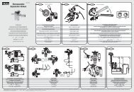
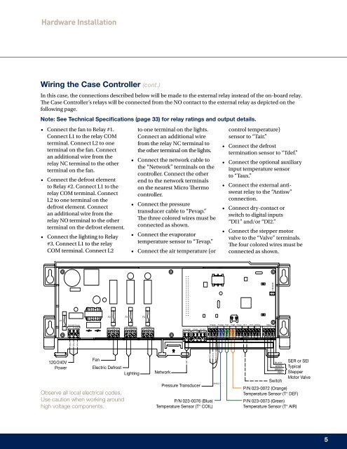
Hardware Installation<br />
Wiring the <strong>Case</strong> <strong><strong>Control</strong>ler</strong> (cont.)<br />
In this case, the connections described below will be made to the external relay instead of the on-board relay.<br />
The <strong>Case</strong> <strong><strong>Control</strong>ler</strong>’s relays will be connected from the NO contact to the external relay as depicted on the<br />
following page.<br />
Note: See Technical Specifications (page 33) for relay ratings and output details.<br />
• Connect the fan to Relay #1.<br />
Connect L1 to the relay COM<br />
terminal. Connect L2 to one<br />
terminal on the fan. Connect<br />
an additional wire from the<br />
relay NC terminal to the other<br />
terminal on the fan.<br />
• Connect the defrost element<br />
to Relay #2. Connect L1 to the<br />
relay COM terminal. Connect<br />
L2 to one terminal on the<br />
defrost element. Connect<br />
an additional wire from the<br />
relay NO terminal to the other<br />
terminal on the defrost element.<br />
• Connect the lighting to Relay<br />
#3. Connect L1 to the relay<br />
COM terminal. Connect L2<br />
to one terminal on the lights.<br />
Connect an additional wire<br />
from the relay NC terminal to<br />
the other terminal on the lights.<br />
• Connect the network cable to<br />
the “Network” terminals on the<br />
controller. Connect the other<br />
end to the network terminals<br />
on the nearest Micro Thermo<br />
controller.<br />
• Connect the pressure<br />
transducer cable to “Pevap.”<br />
The three colored wires must be<br />
connected as shown.<br />
• Connect the evaporator<br />
temperature sensor to “Tevap.”<br />
• Connect the air temperature (or<br />
control temperature)<br />
sensor to “Tair.”<br />
• Connect the defrost<br />
termination sensor to “Tdef.”<br />
• Connect the optional auxiliary<br />
input temperature sensor<br />
to “Taux.”<br />
• Connect the external antisweat<br />
relay to the “Antisw”<br />
connection.<br />
• Connect dry-contact or<br />
switch to digital inputs<br />
“DI1” and/or “DI2.”<br />
• Connect the stepper motor<br />
valve to the “Valve” terminals.<br />
The four colored wires must be<br />
connected as shown.<br />
F1<br />
F2<br />
F3<br />
F4<br />
120/240V Power<br />
L N Earth<br />
FAN ELEC. DEFROST LIGHTING<br />
COM<br />
NO COM NC NO COM NC<br />
NO NC<br />
NETWORK RS485 DC OUT<br />
A B A B 26V Gnd<br />
P evap T evap T air T def T aux Di1 Di2 Antisw Valve<br />
5V S Gnd + - + - + - 2 3 1 4<br />
PWR<br />
PWR<br />
PWR<br />
120/240V<br />
Power<br />
Fan<br />
Electric Defrost<br />
Observe all local electrical codes.<br />
Use caution when working around<br />
high voltage components.<br />
Lighting<br />
Network<br />
Pressure Transducer<br />
NET<br />
RED<br />
WHITE<br />
P/N 023-0076 (Blue)<br />
Temperature Sensor (T° COIL)<br />
BLACK<br />
SHIELD<br />
BLACK<br />
WHITE<br />
GREEN<br />
RED<br />
Switch<br />
P/N 023-0072 (Orange)<br />
Temperature Sensor (T° DEF)<br />
P/N 023-0073 (Green)<br />
Temperature Sensor (T° AIR)<br />
SER or SEI<br />
Typical<br />
Stepper<br />
Motor Valve<br />
5