100-50-5.2 - Sporlan Online
100-50-5.2 - Sporlan Online
100-50-5.2 - Sporlan Online

You also want an ePaper? Increase the reach of your titles
YUMPU automatically turns print PDFs into web optimized ePapers that Google loves.
November 2012 Bulletin / Bulletin <strong>100</strong>-<strong>50</strong>-<strong>5.2</strong> <strong>100</strong>-<strong>50</strong>-<strong>5.2</strong> – Page 1<br />
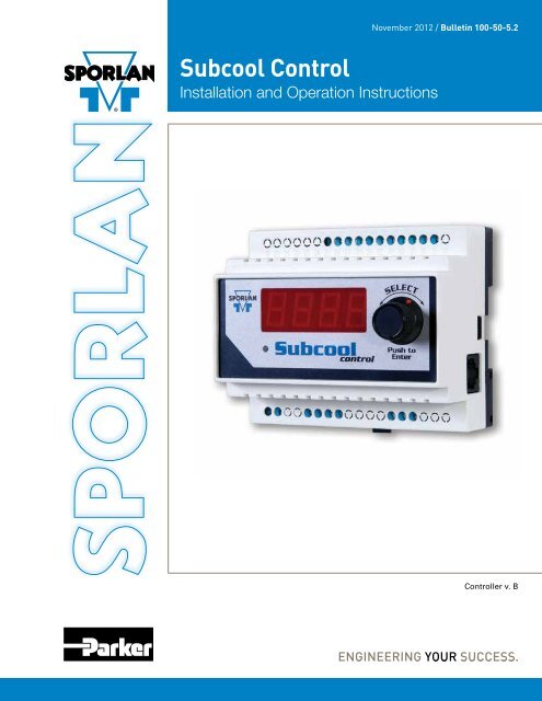
Subcool Control<br />
Installation and Operation Instructions<br />
Controller v. B
Page 2 – Bulletin <strong>100</strong>-<strong>50</strong>-<strong>5.2</strong><br />
Contents<br />
1. Installation ..............................3<br />
2. Setup ..................................4<br />
3. Setpoint Menu Operation ...................4<br />
4. System Operation .........................4<br />
5. Controller Networking ......................5<br />
Scaling for Celsius / Bar ....................5<br />
Setup ..................................5<br />
Modbus Connection Requirements ............5<br />
6. PID Tuning ..............................6<br />
7. Troubleshooting ..........................7<br />
Troubleshooting Recommendations ...........7<br />
Sensors ................................7<br />
APPENDIX A<br />
Setup Menu . . . . . . . . . . . . . . . . . . . . . . . . . . . . . 9<br />
APPENDIX B<br />
Process Values . . . . . . . . . . . . . . . . . . . . . . . . . . . 9<br />
APPENDIX C<br />
Controller Status . . . . . . . . . . . . . . . . . . . . . . . . . . 9<br />
APPENDIX D<br />
Miscellaneous Displays . . . . . . . . . . . . . . . . . . . . 10<br />
APPENDIX E<br />
Setpoint Parameters ......................10<br />
APPENDIX F<br />
Parameter Definitions . . . . . . . . . . . . . . . . . . . . . 12<br />
APPENDIX G<br />
Alarms and Failsafes . . . . . . . . . . . . . . . . . . . . . 13<br />
APPENDIX H<br />
Technical Specifications ...................13<br />
APPENDIX I<br />
Wiring Diagram ..........................14<br />
APPENDIX J<br />
Sensor Installation .......................15<br />
APPENDIX K<br />
MODBUS Memory Map ...................16<br />
APPENDIX L<br />
2k Temperature Sensor Specifications ........18<br />
APPENDIX M<br />
3k Temperature Sensor Specifications ........19<br />
APPENDIX N<br />
Accessories ............................20<br />
APPENDIX O<br />
System Flow Chart .......................20<br />
⚠WARNING – USER RESPONSIBILITY<br />
Failure or improper selection or improper use of the products described herein or related items can cause death, personal injury and property damage.<br />
This document and other information from Parker Hannifin Corporation, its subsidiaries and authorized distributors provide product or system options for further<br />
investigation by users having technical expertise.<br />
The user, through its own analysis and testing, is solely responsible for making the final selection of the system and components and assuring that all performance,<br />
endurance, maintenance, safety and warning requirements of the application are met. The user must analyze all aspects of the application, follow applicable industry<br />
standards, and follow the information concerning the product in the current product catalog and in any other materials provided from Parker or its subsidiaries or<br />
authorized distributors.<br />
To the extent that Parker or its subsidiaries or authorized distributors provide component or system options based upon data or specifications provided by the user,<br />
the user is responsible for determining that such data and specifications are suitable and sufficient for all applications and reasonably foreseeable uses of the<br />
components or systems.<br />
For safety information see the Safety Guide at www.parker.com/safety or call 1-800-CParker.<br />
OFFER OF SALE<br />
The items described in this document are hereby offered for sale by Parker Hannifin Corporation, its subsidiaries or its authorized distributors. This offer and its<br />
acceptance are governed by the provisions stated in the detailed “Offer of Sale” available at www.parker.com.<br />
FOR USE ON REFRIGERATION and/or AIR CONDITIONING SYSTEMS ONLY<br />
For more information about our products visit us at www.sporlan.com.<br />
Bulletin <strong>100</strong>-<strong>50</strong>-<strong>5.2</strong>, November 2012 supersedes SD-358M, June 2012 and all prior publications.
Bulletin <strong>100</strong>-<strong>50</strong>-<strong>5.2</strong> – Page 3<br />
Introduction<br />
The <strong>Sporlan</strong> Subcool<br />
Control is a simple means<br />
of controlling the Electronic<br />
Expansion Valve (EEV) on<br />
most liquid subcooling<br />
systems. The Subcool Control provides liquid<br />
temperature and superheat (pressure-temperature)<br />
control for most common refrigerants. It displays<br />
actual leaving liquid temperature, superheat,<br />
suction pressure, valve position, controller status,<br />
and alarms. It also allows manual control of the<br />
valve position.<br />
Features<br />
• One dial for setting superheat and liquid temperature<br />
• One EEV control (bipolar step motor)<br />
• 4-digit LED display<br />
• Optional controller networking (MODBUS)<br />
• One pressure input (<strong>Sporlan</strong> transducer)<br />
• One digital input (for external switch or relay)<br />
• Three temperature inputs (<strong>Sporlan</strong> surface or air<br />
sensors)<br />
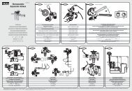
1. Installation<br />
Refer to Appendix I - Wiring Diagram and Appendix J -<br />
Sensor Installation<br />
TOOLS REQUIRED:<br />
• Small flat screwdriver for terminal connections<br />
• Cordless screwdriver<br />
• Phillips and flat screwdrivers<br />
• Needle-nose pliers<br />
• Wire cutters<br />
• Scotch-Brite TM pad<br />
• Two #8 x ½” self-tapping screws to mount DIN rail<br />
1. Mount the controller in a rain-tight, protected location<br />
using the supplied DIN Rail. To leave enough working<br />
space, the suggested mounting area is 10 inches high<br />
and 5 inches wide. The minimum depth is 3 inches. See<br />
Figures 1 and 2.<br />
2. Connect the subcool liquid temperature sensor wires<br />
to terminals 29 and 30. The sensor is not polarized.<br />
Maximum torque on screw terminals is 3.5 in-lbs.<br />
3. Connect the suction temperature sensor wires to terminals<br />
31 and 32. The sensor is not polarized.<br />
4. Connect the pressure transducer wires to terminals 33,<br />
34, and 35. <strong>Sporlan</strong> has used transducer cables with two<br />
wire color combinations; see Table 1 on page 4. If the<br />
cable is spliced in the field to extend its length, ensure<br />
the new wire is properly connected.<br />
5. Connect terminals 25 and 26 to a digital input. A short<br />
or a closed contact from an external relay will close the<br />
valve for pump down. See Section 4 - System Operation,<br />
on page 4.<br />
6. Connect the <strong>Sporlan</strong> EEV wires to terminals 5, 6, 7, and 8.<br />
7. Connect power to terminals 1 and 2. Transformer<br />
requirements are 24 volts AC at 40 VA, Class II.<br />
8. Remove the protective clear film from the front of the<br />
Subcool Control.<br />
WARNING: Use caution when working around<br />
high voltage components. Safety covers should be<br />
used for personal safety on high voltage panels.<br />
NOTE: The <strong>Sporlan</strong> Subcool Control should be installed<br />
only by a qualified professional. All other system components<br />
(valves and sensors) should be supplied by<br />
<strong>Sporlan</strong> to ensure compatibility and proper operation. For<br />
optimal performance, a counterflow heat exchanger is<br />
recommended. There are no user-serviceable components<br />
inside the <strong>Sporlan</strong> Subcool Control. Opening the<br />
case will void the warranty.<br />
5"<br />
127 mm<br />
10"<br />
254 mm<br />
Figure 1 - Recommended Mounting Clearance<br />
4.0" / 102 mm<br />
3.25" / 83 mm<br />
Figure 2 - DIN Rail Detail<br />
.25" / 6.35 mm<br />
1.5"<br />
38 mm
Page 4 – Bulletin <strong>100</strong>-<strong>50</strong>-<strong>5.2</strong><br />
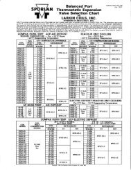
Table 1 - Pressure Transducer Wire Colors<br />
Table 2 - <strong>Sporlan</strong> Electric Expansion Valves<br />
SPORLAN MODEL NUMBERS<br />
2. Setup<br />
CONTROLLER<br />
TERMINAL<br />
OLD PIGTAIL<br />
LEADS<br />
+ 35 Red Black<br />
S 33 Green White<br />
– 34 Black Green<br />
Enter values for four basic system variables; refer to Appendix<br />
A - Setup Menu, page 9. The EEV is closed upon startup and<br />
the system will not operate until completing setup.<br />
Once powered up, the controller will display the firmware<br />
versions for the display and the controller. It will then display<br />
the first variable to set.<br />
1. Set StEP, Step Motor Stroke. Press and then turn the<br />
SELECT knob to select the correct number of steps for<br />
the EEV being used. See Table 2 for a list of <strong>Sporlan</strong><br />
EEVs. Default is 2<strong>50</strong>0. Press the SELECT button again<br />
to enter the value. The next variable is displayed.<br />
2. Set reFr, Refrigerant. Select the actual refrigerant used<br />
in the system (the refrigerant feeding the EEV), following<br />
the steps above. Default is R-404A.<br />
CAUTION: Select the actual refrigerant used in<br />
the system.<br />
3. Set Pt4P, Pressure Sensor Type. Select Absolute or<br />
Gauge, following the steps above. Default is Gauge<br />
(sealed).<br />
4. Set Prng, Pressure Sensor Range. Select 1<strong>50</strong>, 300, or<br />
<strong>50</strong>0, following the steps above. Default is 300.<br />
5. Once setup is complete, the display will alternate<br />
between LovT and the actual Liquid Outlet Temperature.<br />
After the system is in operation, verify that the Liquid<br />
Outlet Temperature Setpoint, LoSP, is met. Default is 75<br />
degrees.<br />
NOTE: If using a 3K temperature probe (or if unsure which<br />
probe you are using) refer to Appendix E, page 10, and<br />
follow the instructions to set the controller to the correct<br />
probe profile. Images of 2K and 3K probes are shown in<br />
Figure 8, page 15.<br />
3. Setpoint Menu Operation<br />
NEW HERMETIC<br />
CABLE<br />
STEPS<br />
SEI-.5, SEI-1, SER-1.5, SEI-2, SEI-3.5, SEI-6,<br />
SER-6, SEI-11, SER-11, SER-20<br />
1596<br />
SER-AA, SER-A, SER-B, SER-C, SER-D,<br />
SER-G, SER-J, SER-K, SER-L<br />
2<strong>50</strong>0<br />
SEI-30 3193<br />
SEI-<strong>50</strong>, SEH-<strong>100</strong>, SEH-175 6386<br />
Make final setpoint changes; refer to Appendix E - Setpoint<br />
Parameters, page 10. The noted values are for verification;<br />
change them if necessary. All other values are for informational<br />
purposes.<br />
NOTE: The Parameter Menu times out after 60 seconds<br />
of inactivity and you will lose all changes entered.<br />
1. Enter the Parameter Menu: Press and hold the SELECT<br />
knob for 5 seconds. Rotate the knob to enter the password<br />
“111 ” and press the SELECT knob again.<br />
2. To change a parameter, rotate the SELECT knob to the<br />
desired parameter and press the SELECT knob. The<br />
default value will display.<br />
3. Turn the SELECT knob to change the value and then<br />
press the SELECT knob to enter the value and return to<br />
the Parameter Menu.<br />
4. After all parameters are set, turn the SELECT knob to<br />
“ESC” and press the SELECT knob to save all changes.<br />
Observe the system for subcool operation. See Appendix<br />
O - System Flowchart, page 21.<br />
The system is now operational. See Appendix B - Process<br />
Values, page 9, for the variables that the Subcool Control<br />
monitors.<br />
4. System Operation<br />
The <strong>Sporlan</strong> Subcool Control uses an interactive control<br />
scheme for Subcooling and Superheat operation. The controller<br />
optimizes the use of the heat exchanger based on the<br />
demand of subcooling loads.<br />
If a third party or master controller is connected to the liquid<br />
line solenoid or suction stop valve, a digital input must be<br />
connected to terminals 25 and 26. This input allows the controller<br />
to respond to major flow variations upstream or downstream<br />
of the subcool control EEV (e.g. ). Closing or shorting<br />
these terminals (when the liquid line solenoid or suction stop<br />
valve closes) places the controller into pumpdown mode and<br />
closes the subcool EEV. During this time, the controller will<br />
shut down the control scheme and prepare for restart. This<br />
ensures maximum control efficiency and system stability.<br />
Two features of the controller allow enhanced operation<br />
as compared to previous subcooling methods.<br />
The first feature is SboF (Subcooler Off Temperature Differential).<br />
The SboF is set as the minimum differential temperature<br />
above the LoSP (Liquid Outlet Temperature Control<br />
Setpoint). When ambient conditions provide a reduced condensing<br />
temperature and the need for subcooling has diminished,<br />
the Subcool Control can be turned off. The optional<br />
liquid inlet temperature sensor measures the liquid drop leg<br />
temperature. At temperatures below SboF + LoSP, the controller<br />
will go into pumpdown mode and close the subcool EEV.<br />
The control status will read OfF. The controller will switch<br />
back to the subcooling mode when the liquid temperature<br />
rises 5°F above the differential temperature (LoVt + SboF +<br />
5 o F).<br />
The second feature, rGhL (Return Gas High Limit), limits the<br />
temperature of the superheated refrigerant returning to the<br />
suction header to a maximum target value. By default, this<br />
setpoint is high in order to provide full functional subcool<br />
control from the factory. If the rGhL is set low, the controller
Bulletin <strong>100</strong>-<strong>50</strong>-<strong>5.2</strong> – Page 5<br />
will override traditional subcool control in order to satisfy<br />
the return gas temperature. In this state, the LoVt temperature<br />
may fall below the setpoint. To access these parameters see<br />
Section 3 - Setpoint Menu Operation, page 4.<br />
Manual Valve Position Feature<br />
The <strong>Sporlan</strong> Subcool Control offers the ability to control<br />
the subcooler expansion valve manually. This feature can be<br />
used in troubleshooting to determine if the expansion valve<br />
responds to an open or closed position signal directly from<br />
the controller. In normal operation, the manual mode should<br />
never be used.<br />
WARNING : Be sure to avoid floodback while using<br />
this feature. Start with the valve in the low position.<br />
Prior to entering manual mode, attach a <strong>Sporlan</strong> Kelvin II remote<br />
display to the RJ-45 port on the side of the Subcool Control<br />
to monitor superheat. This will allow the user to maintain<br />
a minimum superheat while in manual mode by adjusting the<br />
valve position. If the valve is positioned too far open while in<br />
manual mode, superheat will drop and liquid may enter the<br />
suction line. It is always better to start with the valve position<br />
low and work up to a higher position gradually while observing<br />
the superheat value on the remote display. Superheat<br />
should never be allowed to drop below 2°F. If this situation<br />
occurs, reduce valve position and allow system to respond<br />
(superheat should increase).<br />
An alternate way to monitor superheat is to use a gauge set<br />
and a calibrated temperature sensor on the suction line; however<br />
the pressure and temperature will need to be converted to<br />
superheat.<br />
To enter manual mode, press and hold the Select knob, select<br />
111, scroll to Spos and push the knob. See Section 3 - Setpoint<br />
Menu Operation. The valve will start at the current<br />
“original” position. The controller will show percent valve<br />
opening. To verify if the valve is functioning, lower the valve<br />
position by rotating the knob counter-clockwise and note<br />
the change in superheat (increase). From this, increase valve<br />
position slowly and note the change in superheat (decrease). It<br />
may be necessary to allow appropriate time for system to respond<br />
to changes. Ensure superheat does not drop below that<br />
described above. To exit manual operation mode, press encoder<br />
knob, scroll to ESC, and press the knob again. After exiting<br />
manual mode, observe the system for proper operation.<br />
WARNING: The controller should never be left<br />
unattended in manual mode.<br />
The Subcool Control supports the ‘Read Input Registers’,<br />
‘Read Holding Register’, ‘Write Single Register’, ‘Read<br />
Multiple Coils’ and ‘Write Single Coil’ function codes. Other<br />
requests will cause an exception response. The Subcool<br />
Control will allow a full and partial block read of the Input<br />
and Holding registers and coils.<br />
Scaling for Celsius / Bar<br />
For better precision, scaling is used for Bar or Celsius units.<br />
PSI and Fahrenheit values are whole numbers and have no<br />
scaling. See Appendix K - MODBUS Memory Map.<br />
Celsius values transferred via MODBUS are 10X. A value<br />
of 45 will be transferred for the Superheat when the actual<br />
Superheat temperature is 4.5°C. Remember this when changing<br />
a setpoint.<br />
Bar values transferred via MODBUS are <strong>100</strong>X. A value of<br />
1034 will be transferred for the Maximum Operating Pressure<br />
when the actual pressure is 10.34 bar. Remember this when<br />
changing a setpoint.<br />
Setup<br />
The <strong>Sporlan</strong> Subcool Control can be networked to communicate<br />
process variables back to a master controller. This<br />
information can be used for verifying system performance or<br />
updating individual setpoints via RS-485 and PC interface.<br />
Data can be accessed remotely thru the master controller. For<br />
further information on remote monitoring of subcooling, see<br />
corresponding manuals for the master controller.<br />
Prior to establishing the network, each controller must be<br />
assigned a separate address. Refer to Section 3 – Setpoint<br />
Menu Operation to enter setpoint menu. Once in the Setpoint<br />
menu, scroll to AddR and set each controller on the network<br />
with individual addresses. Note: No two controllers can have<br />
the same address. Default address for each controller is ‘1’.<br />
MODBUS Communication Requirements<br />
See Figure 4 - MODBUS Wiring.<br />
Wire Type: 22-24 AWG Universal Twisted Pair<br />
Maximum Number of Network Nodes: <strong>100</strong><br />
Maximum Run Length: 4000 ft<br />
Recommended Network Configuration: Daisy Chain, a<br />
single continuous transmission line from one end to the other.<br />
Other configurations involving triple-lug connections, such as<br />
star, are not recommended. See Figure 3.<br />
5. Controller Networking<br />
The <strong>Sporlan</strong> Subcool Control can communicate with a<br />
MODBUS communication master via RS485 to transfer process<br />
values and setpoints.<br />
The Subcool Control supports only the RTU transmission<br />
mode. The serial settings are:<br />
• 9600 baud (default), 19200 baud, 38400 baud<br />
• 8 data bits<br />
• 1 stop bit<br />
• Even parity (default), odd parity, no parity<br />
Communication<br />
Master<br />
Figure 3 - Daisy Chain<br />
Network Configuration
Page 6 – Bulletin <strong>100</strong>-<strong>50</strong>-<strong>5.2</strong><br />
Figure 4 - Modbus Wiring<br />
Communication<br />
Master<br />
A<br />
B<br />
R T<br />
GND<br />
A<br />
Controller 1<br />
B<br />
with <strong>Sporlan</strong> controllers and master is not recommended. If<br />
necessary, use a separate communication board on the master<br />
to connect separate third-party controllers.<br />
See Appendix K - MODBUS Memory Map, page 16. Also,<br />
refer to the documentation supplied with the communication<br />
master for additional RS485 network requirements.<br />
6. PID Tuning<br />
The <strong>Sporlan</strong> Subcool Control is factory programmed with default<br />
Proportional–Integral–Derivative (PID) settings that will<br />
provide efficient control. It may be necessary, however, to fine<br />
tune the PID settings in applications where systems experience<br />
rapid transient conditions (such as frequent “impulse”<br />
changes in loading or mass flow rates).<br />
GND<br />
A<br />
B<br />
Controller n<br />
R T<br />
GND<br />
Addr - The address of the controller on the MODBUS network.<br />
See Section 3 - Setpoint Menu Operation to change it.<br />
Noise Reduction: Termination resistance (R T<br />
in Figure 4)<br />
is recommended to reduce reflections and noise on the data<br />
transmission lines. Place the resistance at the extreme ends of<br />
the cable with the resistance value matching the characteristic<br />
impedance of the transmission line (typically 120 ohms for<br />
twisted pair cables).<br />
Shielding prevents noise from EMI sources. If the cable is<br />
shielded, connect the shield to earth ground at one end only.<br />
Do not connect shield to RS485 GND.<br />
Keep RS485 wiring away from high voltage AC lines to<br />
reduce noise and data errors on communication lines. RS485<br />
communication cable should be perpendicular to AC lines at<br />
any intersection.<br />
Grounding: Connect a third conductor to RS485 GND (pin<br />
13) to prevent ground potentials from node to node. This<br />
conductor should be included in the shield of the twisted pair<br />
cable to prevent noise. Do not connect RS485 GND to earth<br />
ground.<br />
Third Party Controllers: To avoid nuisance “network errors”,<br />
the use of third party controllers on the same RS485 network<br />
A<br />
B<br />
R T<br />
Controller n-1<br />
- Termination<br />
resistor<br />
The controller offers PID adjustments for both Subcooled<br />
liquid temperature and Superheat control. In most instances,<br />
adjustments to the PI set-points are adequate. If tuning is<br />
needed, see Section 3 - Setpoint Menu Operation to enter<br />
the PID setpoint menu. The following guidelines should be<br />
followed:<br />
• Lp (Liquid Proportional Coefficient) – Increase value to<br />
increase valve response to Subcooled liquid out temperature.<br />
• Li (Liquid Integral Coefficient) – Increase value to<br />
decrease valve response to Subcooled liquid out temperature<br />
over a given time period.<br />
• Ld (Liquid Derivative Coefficient) – Increase value to<br />
increase valve response to rate of change in Subcooled<br />
liquid out temperature.<br />
• Sp (Superheat Proportional Coefficient) – Increase value<br />
to increase valve response to Superheat.<br />
• Si (Superheat Integral Coefficient) – Increase value to<br />
decrease valve response to Superheat over a given time<br />
period.<br />
• Sd (Superheat Derivative Coefficient) – Increase value to<br />
increase valve response to rate of change in Superheat.<br />
• LSHi (Low Superheat Integral Coefficient) – Increase<br />
value to decrease valve response to superheat over a given<br />
time period (Only in low Superheat conditions).<br />
If PID adjustments are made, allow adequate time for the<br />
system to respond to the changes.<br />
Large oscillations in Subcooled liquid or Superheat may<br />
require adjustments to the respective PID values. If Subcooled<br />
liquid and Superheat are equally unstable, adjust the Superheat<br />
PID values first, followed by the liquid PID values.<br />
• When the Superheat is oscillating to extremes, the Proportional<br />
value may be too high and/or the Integral value<br />
may be too low.<br />
• If the Superheat is not oscillating to extremes, but the<br />
Liquid control is very inconsistent around setpoint, then<br />
the Proportional value may need to be reduced or the<br />
Integral value increased.
Bulletin <strong>100</strong>-<strong>50</strong>-<strong>5.2</strong> – Page 7<br />
These actions are inversely proportional in nature. If the subcooled<br />
liquid temperature or Superheat are slow to react to a<br />
transient system change, then the Proportional may be too low<br />
and or the Integral value may be too high in value.<br />
Note: Not all refrigeration systems are designed alike. Use<br />
caution when tuning PID setpoints.<br />
7. Troubleshooting<br />
Recommendations<br />
As with any refrigeration component troubleshooting, actual<br />
system conditions should be verified with a gauge set and<br />
calibrated temperature sensor (i.e verify actual superheat,<br />
subcooling and refrigerant condition). This system information<br />
is valuable in determining whether it is component<br />
related or system related.<br />
For systems or applications that experience light loads on the<br />
Subcool control circuit, it is important that the Heat exchanger<br />
and refrigerant lines are sized correctly. This will ensure<br />
proper oil return and will minimize the effects of oil logging<br />
in the Heat exchanger. Many Heat exchanger manufacturers<br />
recommend a hot gas bypass for loads below <strong>50</strong>%. Refer to<br />
the heat exchanger manufacturer’s installation instructions.<br />
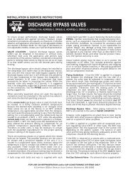
Pressure transducers should be tested while connected to<br />
the controller and powered. Test at the controller terminals.<br />
Voltage between terminals 34 and 35 should be 4.8 - <strong>5.2</strong> volts<br />
DC. Voltage between 33 and 34 should be between 0.5 and<br />
4.5 volts DC. See Table 1 - Pressure Transducer Wire Colors,<br />
page 4.<br />
To test the accuracy of the transducer, use a gauge set to<br />
obtain the actual system pressure. For volts-to-pressure<br />
conversion, measure the voltage between terminals 33 and<br />
34. Identify the pressure transducer used and find the correct<br />
range Prng in Table 3.<br />
Substitute the measured voltage (v) in the formula in the PSI<br />
column. The result should be within 3 psi of the actual system<br />
pressure shown on the gauge set. If not, check transducer for<br />
proper installation, correct schrader valve, and verify the pressure<br />
range identified on the transducer.<br />
To test the transducer cable, disconnect the cable from the<br />
transducer and check for 4.8 - <strong>5.2</strong> volts between terminals +<br />
and – . See Figure 5 - Pressure Sensor Cable.<br />
Figure 5 - Pressure Sensor Cable<br />
Sensors<br />
Failed sensors will trigger an alarm. An alarm code will show<br />
which sensor is mis-wired, disconnected, or faulty. (See Appendix<br />
G - Alarms and Failsafes, page 13) The alarm will<br />
persist until the problem is corrected.<br />
Failed temperature sensors will generally read extremely<br />
low or infinite resistance when tested with an ohmmeter.<br />
Readings should be taken with the sensor disconnected from<br />
the Subcool Control. A missing or disconnected temperature<br />
sensor will read -60 on the controller.<br />
Temperature sensor output can be checked by measuring the<br />
DC voltage across the sensor wire using the tables in Appendix<br />
L, page 18 and Appendix M, page 19.<br />
+<br />
–<br />
S<br />
Since the liquid and suction temperature sensors are identical,<br />
no alarm will be triggered if the sensors are switched (i.e. liquid<br />
sensor on the suction line). Severe system damage may<br />
occur if these two sensor locations are interchanged.<br />
Pressure transducers must be installed tight enough to depress<br />
the valve stem in the fitting. Failure to do so will result<br />
in erroneous pressure readings and possibly leaks.<br />
Table 3 - Pressure Transducer Specifications<br />
LABEL COLOR Prng PSI<br />
Green 1<strong>50</strong> (v-.5) x 37.5<br />
None / Silver 300 (v-.5) x 75<br />
Yellow <strong>50</strong>0 (v-.5) x 125
Page 8 – Bulletin <strong>100</strong>-<strong>50</strong>-<strong>5.2</strong><br />
Table 4 - Troubleshooting<br />
SYMPTOM<br />
Will not power up<br />
Subcooling below<br />
setpoint<br />
Subcooling above<br />
setpoint<br />
No Subcooling<br />
Subcooling Unstable<br />
No Communication<br />
Communication errors<br />
Setpoints not saved<br />
CHECK<br />
Wiring terminals (power) at transformer and controller<br />
Supply voltage (see Technical Specification section)<br />
EPR valve setting (too low)<br />
Pressure Transducer Range (correct transducer set up in controller; 0-300, etc.)<br />
Pressure Transducer Type (correct transducer set up in controller; gauge/sealed versus absolute)<br />
Temperature Sensor Type (correct sensor set up in controller; 2K or 3K (see Appendix J - Sensor<br />
Installation, page 15)<br />
Temperature Sensor wiring (ensure sensor locations are not mis-matched)<br />
Proper foam insulation on piping and sensors<br />
Return Gas High Limit (rghL) set too low<br />
EPR valve setting (too high)<br />
Liquid condition entering expansion valve<br />
Pressure Transducer Range (correct transducer set up in controller; 0-300, etc.)<br />
Temperature Sensor Type (correct sensor set up in controller; 2K or 3K, see Appendix J - Sensor<br />
Installation, page 15)<br />
Subcool Control expansion valve (correct valve set up in controller; 1596, 2<strong>50</strong>0 steps, etc.)<br />
Subcool Control expansion valve sizing (if valve position in controller is at <strong>100</strong>% when symptom<br />
exists, valve may be undersized)<br />
Heat exchanger sizing<br />
Proper system refrigerant charge<br />
Oil return (oil logging in heat exchanger)<br />
Liquid line filter (clogging or excessive pressure drop)<br />
Subcool Control power<br />
Pump down signal (ensure Subcool Control expansion valve is not closed)<br />
Proper system refrigerant charge<br />
Liquid line filter (clogging or excessive pressure drop)<br />
Proper Subcooler Off Temperature Differential (o) (see Section 4 - System Operation, page 4)<br />
Subcool Control Expansion Valve operation<br />
Wiring terminals (power) at transformer and controller<br />
Wiring terminals (sensors) at controller<br />
Sensor locations<br />
Sensor operation (See additional information under Section 7 - Troubleshooting, page 7)<br />
Proper heat exchanger flow direction<br />
Stability of head pressure control valves (upstream of Subcool Control expansion valve)<br />
Stability of suction pressure control valves (downstream of Subcool Control expansion valve)<br />
Stability of rack controller (verify compressors are not short cycling)<br />
Controller PID setting (See Section 6 - PID Tuning, page 6)<br />
Wiring at controller and master communication board<br />
Addresses of controllers (see Section 5 - Controller Networking, page 5)<br />
Wiring terminals at controller and master communication board<br />
Network wiring from controller to master communication board (see Section 5 - Controller<br />
Networking, page 5)<br />
Proper network wire grounding (see Section 5 - Controller Networking, page 5)<br />
Termination resistors (see Section 5 - Controller Networking, page 5)<br />
Network parameters in controller and master communication board (baud rate, parity, etc; see<br />
Section 5, page 5)<br />
Third party controllers on Subcool Control network<br />
ESC must be set within 60 seconds of changes being made
APPENDIX A - Setup Menu<br />
Bulletin <strong>100</strong>-<strong>50</strong>-<strong>5.2</strong> – Page 9<br />
SETUP MENU<br />
<br />
Valve Type<br />
Default is 2<strong>50</strong>0<br />
Display Readout Description<br />
<br />
1596 Step Bipolar Valve<br />
3193 3193 Step Bipolar Valve<br />
<br />
2<strong>50</strong>0 Step Bipolar Valve<br />
<br />
6386 Step Bipolar Valve<br />
<br />
400 Step Unipolar Valve<br />
<br />
Refrigerant Type<br />
Default is 404A<br />
NOTE: Select the actual<br />
refrigerant used in the<br />
system.<br />
Counterclockwise<br />
Display Readout Description<br />
R-22<br />
<br />
R-134a<br />
<br />
R-402A<br />
<br />
R-404A<br />
<br />
R-407A<br />
<br />
R-407C<br />
410A<br />
R-410A<br />
417A<br />
R-417A<br />
<br />
R-422A<br />
<br />
R-422D<br />
<br />
R-<strong>50</strong>7A<br />
R-744<br />
<br />
R-245FA<br />
<br />
R-E5<br />
<br />
R-438A<br />
<br />
R-401B<br />
Clockwise<br />
4<br />
Pressure Sensor Type<br />
Default is Gauge<br />
Display Readout<br />
<br />
<br />
Description<br />
Absolute Pressure Type<br />
Gauge (Sealed) Pressure Type<br />
<br />
Pressure Sensor Range<br />
Default is 300<br />
Display Readout<br />
<br />
<br />
<br />
Description<br />
0-1<strong>50</strong> PSI<br />
0-300 PSI<br />
0-<strong>50</strong>0 PSI<br />
Default values are highlighted.<br />
APPENDIX B - Process Values<br />
PROCESS<br />
DESCRIPTION<br />
End<br />
Controller display address CADR must be<br />
reset*<br />
LovT Liquid Outlet Temperature<br />
SvPH Superheat (tout-tsat)<br />
SvcP Suction Pressure<br />
Conversion of suction pressure to its<br />
tSAt<br />
saturated temperature<br />
tovt Sensible heat out of the evaporator<br />
PoSn Position of the EEV step motor<br />
Lin Liquid Inlet Temperature (Optional)<br />
S-4 Status of the Auxiliary Temperature Input<br />
Stat Controller Status<br />
ALS Controller Alarms<br />
APPENDIX C - Controller Status<br />
DISPLAY<br />
CooL<br />
pdn<br />
StPo<br />
Off<br />
DESCRIPTION<br />
Subcool On (Valve modulating)<br />
Pumpdown (Valve closed)<br />
Stepper Override (Manual valve control)<br />
Shown when manually controlling valve<br />
through remote display or Modbus<br />
Subcool Off (Valve closed)<br />
When Sbof and optional Liquid In temperature<br />
sensor is used, see Section 4 - System<br />
Operation<br />
*If the controller display is alternating between Ctrl, and either<br />
a number 1-99 or LocL, then scroll to LocLand press the Select<br />
knob to view the local controller attached to this display. Then<br />
press and hold the Select knob for approximately 5 seconds and<br />
enter password111 when prompted. Scroll to CADR (Controller<br />
address) and set it to 0. Exit the setpoint menu.
Page 10 – Bulletin <strong>100</strong>-<strong>50</strong>-<strong>5.2</strong><br />
APPENDIX D - Miscellaneous Displays<br />
DISPLAY<br />
End<br />
BAD<br />
LocL<br />
Ctrl<br />
DESCRIPTION<br />
Press SELECT knob to exit menu<br />
The wrong password has been entered<br />
Shows that readings refer to current controller<br />
Shows which controller is displayed<br />
APPENDIX E - Setpoint Parameters<br />
PARAMETERS<br />
Counterclockwise<br />
Escape and Save Settings —<br />
LoSP<br />
rghL<br />
o<br />
<br />
<br />
Chosen<br />
at Setup<br />
Liquid Outlet Temperature Setpoint<br />
Change to desired Liquid Out Temperature<br />
Return Gas High Limit<br />
Subcooler Off Temperature Differential<br />
Superheat Setpoint<br />
Change to desired Superheat Setpoint<br />
Refrigerant Type<br />
Change to desired Refrigerant Type<br />
10 to <strong>100</strong>°F (-12.3 to 37.7°C)<br />
Default is 75°F (23.8°C)<br />
40 to 120°F (4.4 to 48.8°C)<br />
Default is 120°F (48.8°C)<br />
0 to 30°F (0 to 16.7°C)<br />
Default is 10°F (5.5°C)<br />
5 to 45°F (2.8 to 25°C)<br />
Default is 10°F (5.5°C)<br />
Readout Description<br />
R-22<br />
<br />
R-134A<br />
<br />
R-402A<br />
<br />
R-404A<br />
<br />
R-407A<br />
<br />
R-407C<br />
410A<br />
R-410A<br />
417A<br />
R-417A<br />
<br />
R-422A<br />
<br />
R-422D<br />
<br />
R-<strong>50</strong>7A<br />
R-744<br />
<br />
R-245FA<br />
<br />
R-E5<br />
<br />
R-438A<br />
401b<br />
R-401B<br />
Maximum Valve Capacity 0 to <strong>100</strong>% Default is <strong>100</strong><br />
Liquid Proportional Coefficient<br />
0 to 25.5 Default is 1.0<br />
Increase value to increase valve response to<br />
liquid out temperature<br />
Liquid Integral Coefficient<br />
0 to 255 Default is 60<br />
Increase value to decrease valve response<br />
to liquid out temperature over time<br />
Liquid Derivative Coefficient<br />
0 to 255 Default is 0<br />
Increase value to increase valve response to<br />
change in liquid out temperature<br />
Superheat Proportional Coefficient<br />
0 to 25.5 Default is 1.0<br />
Increase value to increase valve response to<br />
superheat<br />
Superheat Integral Coefficient<br />
0 to 255 Default is 120<br />
Increase value to decrease valve response<br />
to superheat over time<br />
Superheat Derivative Coefficient<br />
0 to 255 Default is 0<br />
Increase value to increase valve response to<br />
change in superheat<br />
Default values are highlighted.<br />
Clockwise
APPENDIX E - Setpoint Parameters (continued)<br />
PARAMETERS<br />
Bulletin <strong>100</strong>-<strong>50</strong>-<strong>5.2</strong> – Page 11<br />
LSHi Low Superheat Integral Coefficient<br />
1 to 255 Default is 10<br />
Increase value to decrease valve response<br />
to superheat over time, low Superheat<br />
condition<br />
4 Cycle Time 1 to 10 seconds Default is 1<br />
<br />
Chosen<br />
at Setup<br />
Valve Type<br />
Readout Description<br />
<br />
1596 Step Bipolar Valve<br />
3193 3193 Step Bipolar Valve<br />
<br />
2<strong>50</strong>0 Step Bipolar Valve<br />
<br />
6386 Step Bipolar Valve<br />
<br />
400 Step Unipolar Valve<br />
Manual Valve Position 0 to <strong>100</strong>% Open Default is 0<br />
MODBUS Network Address 1 to 255 Default is 1<br />
BavD<br />
MODBUS Baud Rate<br />
Readout Description<br />
96 9600<br />
192 19200<br />
384 38400<br />
<br />
MODBUS Network Parity<br />
Readout<br />
<br />
<br />
<br />
Description<br />
No Parity<br />
Even Parity<br />
Odd Parity<br />
Counterclockwise<br />
<br />
<br />
t4p<br />
Pressure Units<br />
Temperature Units<br />
Temperature Sensor Type<br />
Readout<br />
<br />
<br />
Readout<br />
<br />
<br />
Readout<br />
typ3<br />
typ2<br />
Description<br />
Pounds Force Per<br />
Square Inch<br />
Bars<br />
Description<br />
Fahrenheit<br />
Celsius<br />
Description<br />
3k<br />
2k<br />
Clockwise<br />
4<br />
Chosen<br />
at Setup<br />
Pressure Sensor Type<br />
Readout<br />
<br />
v<br />
Description<br />
Absolute Pressure Type<br />
Gauge (Sealed) Pressure<br />
Type<br />
<br />
Chosen<br />
at Setup<br />
Pressure Sensor Range<br />
Readout<br />
<br />
<br />
<br />
Description<br />
0-1<strong>50</strong> PSI<br />
0-300 PSI<br />
0-<strong>50</strong>0 PSI<br />
Pressure Sensor Calibration Offset -5 to 5 PSI (-0.34 to 0.34 Bar) Default is 0<br />
Suction Temperature Calibration Offset -5 to 5°F (-2.7 to 2.7°C) Default is 0<br />
<br />
Liquid Outlet Temperature<br />
Calibration Offset<br />
-5 to 5°F (-2.7 to 2.7°C) Default is 0<br />
<br />
Liquid Inlet Temperature<br />
Calibration Offset<br />
-5 to 5°F (-2.7 to 2.7°C) Default is 0<br />
Auxiliary Temperature Calibration Offset -5 to 5°F (-2.7 to 2.7°C) Default is 0<br />
Controller Display Address 0 to 99 Default is 0, Do not change<br />
Default values are highlighted.
Page 12 – Bulletin <strong>100</strong>-<strong>50</strong>-<strong>5.2</strong><br />
APPENDIX F - Parameter Definitions<br />
DISPLAY MEANING DESCRIPTION<br />
Escape from the Settings Menu and Return to Process<br />
ESC Escape<br />
Variables Menu<br />
The target control temperature of the liquid leaving the<br />
LoSP Liquid Outlet Temperature Control Setpoint<br />
heat exchanger<br />
Limits the temperature of the superheated refrigerant to a<br />
rghL Return Gas High Limit<br />
maximum target value (Limits superheat PID target)<br />
Temperature differential above the liquid outlet temperature<br />
setpoint that the liquid inlet temperature must fall<br />
below in order to switch to OFF mode. Will switch back to<br />
SboF Subcooler Off Temperature Differential<br />
cooling after the liquid inlet temperature rises above the<br />
liquid outlet temperature + subcooler off temperature<br />
differential + 5 degrees F<br />
The minimum target superheat setpoint that the superheat<br />
SHSP Superheat Setpoint<br />
PID can try to maintain<br />
The currently selected refrigerant used to calculate the<br />
rEFr Refrigerant<br />
saturation temperature based on suction pressure<br />
HiCP Maximum Stepper % Open The maximum % open of the valve referenced to full stroke<br />
-LP- Liquid Proportional Gain Coefficient Liquid Proportional Gain Coefficient<br />
-LI- Liquid Integral Gain Coefficient Liquid Integral Gain Coefficient<br />
-Ld- Liquid Derivative Gain Coefficient Liquid Derivative Gain Coefficient<br />
-SP- Superheat Proportional Gain Coefficient Superheat Proportional Gain Coefficient<br />
-SI- Superheat Integral Gain Coefficient Superheat Integral Gain Coefficient<br />
-Sd- Superheat Derivative Gain Coefficient Superheat Derivative Gain Coefficient<br />
The integral gain coefficient to use for the superheat PID<br />
LSHi Low Superheat Integral Gain Coefficient<br />
loop if the superheat is below 3 degrees F<br />
CyCt Cycle Time The PID update time<br />
The number of steps of resolution for the stepper valve at<br />
StEP Stepper Type<br />
full stroke<br />
Overrides the stepper valve position and moves to the<br />
SPoS Manual Stepper Position<br />
desired percent open relative to full stroke of the valve<br />
Addr Network Address The address of the controller on the MODBUS network<br />
The baud rate in hundreds of bits per second of the MODbAvd<br />
Network Baud Rate<br />
BUS network<br />
nPAr Network Parity Mode The network parity mode of the MODBUS network<br />
The units of pressure the controller uses to display (PSI or<br />
Un_P Units of Pressure<br />
Bar)<br />
The units of temperature the controller uses to display<br />
Un_t Units of Temperature<br />
(Fahrenheit or Celsius)<br />
The type of thermistor connected to the controller (2K type<br />
tt4P Temperature Sensor Type<br />
or 3K type)<br />
The type of pressure sensor connected to the controller<br />
Pt4P Pressure Sensor Type<br />
(absolute or gauge type)<br />
The range of the pressure sensor connected to the controller<br />
(0-1<strong>50</strong> PSI, 0-300 PSI, or 0-<strong>50</strong>0 PSI)<br />
Prng Pressure Sensor Range<br />
CALP Pressure Calibration Offset Adds a constant offset to the pressure reading<br />
CLt1 T1 Temperature Calibration Offset Adds a constant offset to the T1 temperature reading<br />
CLt2 T2 Temperature Calibration Offset Adds a constant offset to the T2 temperature reading<br />
CLt3 T3 Temperature Calibration Offset Adds a constant offset to the T3 temperature reading<br />
CLt4 T4 Temperature Calibration Offset Adds a constant offset to the T4 temperature reading<br />
Controller must be set to 0 (Standalone) No display networking<br />
Cadr Controller Address on Display Network<br />
option
Bulletin <strong>100</strong>-<strong>50</strong>-<strong>5.2</strong> – Page 13<br />
APPENDIX G - Alarms and Failsafes<br />
READOUT DESCRIPTION CAUSE and FAILSAFE<br />
nonE No Active Alarms Normal Operation<br />
PSAL<br />
tSAL<br />
LSAL<br />
LSHA<br />
Pressure Sensor Alarm<br />
Suction Temperature Sensor Alarm<br />
Liquid Outlet Temperature Sensor<br />
Alarm<br />
Low Superheat Alarm<br />
When the pressure is outside the operating range. Will force a<br />
pump-down.<br />
When the suction temperature is outside the operating range.<br />
(under -60 degrees, over 1<strong>50</strong> degrees) Will force a pump-down.<br />
When the liquid outlet temperature is outside the operating<br />
range. Will force a pump-down.<br />
When superheat is below 3 degrees for 30 cumulative seconds<br />
or more.<br />
APPENDIX H - Technical Specifications<br />
ELECTRICAL<br />
Supply Voltage<br />
20-26VAC <strong>50</strong>/60Hz or 22-26.6VDC; Class II input<br />
Digital Inputs<br />
0-5VDC Maximum Range<br />
Interface to dry contact or open collector<br />
Analog Inputs<br />
4 Temperature Sensors - 2 Kohm (3 Kohm optional)<br />
1 Pressure Transducer .5 - 4.5VR<br />
(1<strong>50</strong> psig, 300 psig, or <strong>50</strong>0 psig)<br />
Digital Display<br />
LED - Red, 7 segment, 4 digit<br />
Indicators<br />
LED - Red, Power<br />
User Interface<br />
Optical Encoder (SELECT knob)<br />
Data Interface<br />
RS485, Modbus<br />
MECHANICAL<br />
Operating Temperature<br />
-40°F to 158°F (-40°C to 70°C)<br />
Humidity<br />
0-95%RH (Non-Condensing)<br />
Enclosure<br />
PC - Light Gray<br />
Wiring<br />
Screw terminal<br />
Mounting<br />
DIN Rail - EN <strong>50</strong> 022<br />
COMPLIANCE<br />
Environmental<br />
RoHS<br />
WEEE<br />
Electrical<br />
CE<br />
UL/CUL (Recognized per 873)<br />
FCC (Class A, part 15)<br />
C-tick
Page 14 – Bulletin <strong>100</strong>-<strong>50</strong>-<strong>5.2</strong><br />
APPENDIX I - Wiring Diagram<br />
Pumpdown<br />
Relay<br />
24V<br />
AC/DC<br />
Black<br />
White<br />
Green<br />
Red<br />
Dry Contacts (T4)<br />
Liquid Inlet Temp. (T3)<br />
Liquid Outlet Temp. (T2)<br />
Note: Use caution when working around<br />
high voltage components. Safety covers<br />
should be used for personal safety on high<br />
voltage panels.<br />
Ground<br />
A+<br />
B-<br />
RS485<br />
minimize<br />
1”- 2” ideal<br />
10”-14”<br />
Pressure<br />
Transducer<br />
Suction<br />
Temperature Sensor<br />
Warm Liquid In<br />
(optional)<br />
Temperature Sensor<br />
Evap. Outlet Temp. (T1)<br />
White<br />
Green<br />
Black<br />
Liquid<br />
Temperature Sensor<br />
Counter Flow<br />
Brazed Plate<br />
Heat Exchanger<br />
Subcooled<br />
Liquid Out<br />
10”-14”<br />
**<br />
EEV<br />
Liquid Line<br />
Solenoid Valve<br />
* Refer to the heat exchanger manufacturer’s<br />
installation/orientation instructions.<br />
L2<br />
L1
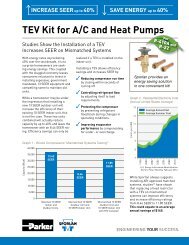
APPENDIX J - Sensor Installation<br />
Refer to Appendix I - Wiring Diagram for sensor locations.<br />
Mount the Pressure Transducer<br />
1. Position the suction return gas pressure access port near<br />
the outlet of the heat exchanger.<br />
2. Verify that the pressure range matches the expected system<br />
operating pressure (i.e 0-1<strong>50</strong> psig, 0-300 psig, etc).<br />
3. Install transducer on access port at 12 o’clock, minimizing<br />
distance from temperature sensor. Check for leaks.<br />
4. For safety, ensure Schrader core is installed in access<br />
fitting (only if ¼” SAE is used). Use caution when removing<br />
Schrader cap to avoid contacting expanding<br />
refrigerant.<br />
5. Connect pressure transducer cable to transducer.<br />
6. Route and secure transducer cable away from hot surfaces<br />
and high power A/C voltage lines.<br />
7. Attach wires to the Subcool Control.<br />
8. Ensure pressure range and type (i.e gauge or absolute) are<br />
configured properly in the Subcool Controller, See Section<br />
2 - SETUP, page 4.<br />
9. After startup, use a gauge set to verify proper pressure<br />
reading through the Subcool Control. An improperly<br />
installed Schrader core can cause erroneous pressure<br />
readings.<br />
10. Check for leaks after system is in operation.<br />
Mount the Temperature Sensors – Suction and<br />
Liquid<br />
1. Per Appendix I - Wiring Diagram, page 14, measure and<br />
mark locations on copper pipe. Position sensors 10-14<br />
inches from the heat exchanger on a free-draining horizontal<br />
line.<br />
2. Remove all insulation and adhesives at the marked location.<br />
Using Scotch-Brite TM , clean the copper line to remove<br />
oxides and dirt. This will increase sensor accuracy.<br />
3. Fasten the temperature sensors in orientation shown in<br />
Figure 6. Carefully note the locations of temperature<br />
sensors for Suction Gas and Liquid.<br />
• Mount the suction temperature sensor on the suction<br />
line after the heat exchanger, near the pressure transducer.<br />
• Mount the subcool liquid temperature sensor on the<br />
subcooled liquid outlet.<br />
4. Attach and secure temperature sensor cables, routing<br />
them away from hot surfaces and high power A/C voltage<br />
lines.<br />
5. Ensure that the Subcool Control is configured properly<br />
(i.e 2K or 3K sensor selection), See Section 2 - SETUP,<br />
page 4. NOTE: 2K and 3K sensors have approximately<br />
1.9kΩ and 2.8kΩ, respectively, at 80°F measured<br />
across the sensor wires.<br />
6. Wrap temperature sensors and copper tube with foam<br />
insulation to minimize ambient temperature effects, See<br />
Figure 7.<br />
Bulletin <strong>100</strong>-<strong>50</strong>-<strong>5.2</strong> – Page 15<br />
Figure 6 - Temperature Sensor Positioning<br />
Temperature sensor should be mounted at either 4 or<br />
8 o’clock, on a free-draining horizontal line.<br />
Figure 7 - Cutaway of Pipe Insulation<br />
2K sensor shown<br />
Figure 8 - Temperature Sensors<br />
2K sensor<br />
3K sensor<br />
WARNING: Ensure that “Suction” and “Liquid” temperature<br />
sensor locations are not reversed. Severe<br />
system damage may occur if these two sensor<br />
locations are interchanged.
Page 16 – Bulletin <strong>100</strong>-<strong>50</strong>-<strong>5.2</strong><br />
APPENDIX K - MODBUS Memory Map<br />
Register Address/Description<br />
Range<br />
Read Coils (0x01) 0. Manual Valve Enabled Flag 0 = Disabled<br />
1 = Enabled<br />
1. Manual Valve Duration Enabled Flag 0 = Disabled<br />
1 = Enabled<br />
Read Holding Register<br />
(0x03)<br />
0. Liquid Outlet Temperature Setpoint 10 to <strong>100</strong>°F (-12.2 to 37.8°C)<br />
1. Return Gas Temperature Limit 10 to 120°F (-12.2 to 48.9°C)<br />
2. Subcooler Off Temperature Differential 0 to 30°F (0 to -16.7°C)<br />
3. Superheat Setpoint 5 to 45°F (2.8 to 25°C)<br />
6. Refrigerant Type 0 = R-22<br />
1 = R-134A<br />
2 = R-402A<br />
3 = R-404A<br />
4 = R-407A<br />
5 = R-407C<br />
6 = R-410A<br />
7 = R-417A<br />
7. Valve Maximum 0 to <strong>100</strong>%<br />
8. Liquid Proportional Coefficient 0 to 255<br />
9. Liquid Integral Coefficient 0 to 255<br />
10. Liquid Derivative Coefficient 0 to 255<br />
11. Superheat Proportional Coefficient 0 to 255<br />
12. Superheat Integral Coefficient 0 to 255<br />
13. Superheat Derivative Coefficient 0 to 255<br />
8 = R-422A<br />
9 = R-422D<br />
10 = R-<strong>50</strong>7A<br />
11 = R-744<br />
12 = R-245FA<br />
13 = R-E5<br />
14 = R-438A<br />
15 = R-401B<br />
14. Cycle Time 1 to 10 seconds<br />
15. Valve Type 0 = 1596<br />
1 = 3193<br />
2 = 2<strong>50</strong>0<br />
3 = 6386<br />
4 = 400<br />
16. Manual Valve Position 0 to <strong>100</strong>0 (0 to <strong>100</strong>.0%) Open<br />
17. MODBUS Network Address 1 to 255<br />
18. Pressure Units 0 = PSI<br />
1 = BAR<br />
19. Temperature Units 0 = FAHR<br />
1 = CELS<br />
20. Pressure Sensor Type 0 = ABSL<br />
1 = GauG<br />
21. Pressure Range 1 = 1<strong>50</strong> PSI<br />
2 = 300 PSI<br />
3 = <strong>50</strong>0 PSI<br />
22. Pressure Calibration Offset -5 to 5 PSI (-0.34 to 0.34 Bar)<br />
23. Suction Temperature Calibration Offset -5 to 5°F (-2.8 to 2.8°C)<br />
24. Liquid Outlet Temperature Calibration Offset -5 to 5°F (-2.8 to 2.8°C)<br />
25. Liquid Inlet Temperature Calibration Offset -5 to 5°F (-2.8 to 2.8°C)<br />
26. Auxiliary Temperature Calibration Offset -5 to 5°F (-2.8 to 2.8°C)<br />
27. Temperature Sensor Type 0 = 3K<br />
1 = 2K<br />
28. Low Superheat Integral 1-255, Default is 10
APPENDIX K - MODBUS Memory Map (continued)<br />
Bulletin <strong>100</strong>-<strong>50</strong>-<strong>5.2</strong> – Page 17<br />
Read Input<br />
Registers (0x04)<br />
Write Single Coil<br />
(0x05)<br />
Write Single Register<br />
(0x06)<br />
Register Address/Description<br />
Range<br />
0. Controller FW Rev Level 0 to 65,535<br />
1. Liquid Outlet Temperature -60 to 1<strong>50</strong>°F (-51.1 to 65.6°C)<br />
2. Superheat 0 to 165°F (0 to 91.6°C)<br />
3. Suction Pressure Depends on Pressure Sensor Range<br />
and Type<br />
(-15 to <strong>50</strong>0 PSI, -1.01 to 34.47 Bar)<br />
Maximum Range<br />
4. Saturation Temperature -60 to 1<strong>50</strong>°F (-51.1 to 65.6°C)<br />
5. Suction Temperature -60 to 125°F (-51.1 to 65.6°C)<br />
6. Valve Position (% of Max. Stroke) 0 to <strong>100</strong>0 (0 to <strong>100</strong>.0%) Open<br />
7. Liquid Inlet Temperature -60 to 125°F (-51.1 to 65.6°C)<br />
8. Auxiliary Temperature -60 to 125°F (-51.1 to 65.6°C)<br />
9. System State If Bit set then mode is active:<br />
Bit 0 = Setup Mode<br />
Bit 1 = Off Cycle<br />
Bit 2 = Cooling Cycle<br />
Bit 3 = Pump-down Cycle<br />
Bit 4 = Manual Valve Override Mode<br />
10. Alarm Status If Bit set then alarm is active:<br />
Bit 0 = Pressure Sensor Failure<br />
Alarm<br />
Bit 1 = Suction Temperature Sensor<br />
Failure Alarm<br />
Bit 2 = Liquid Outlet Temperature<br />
Sensor Failure Alarm<br />
Bit 3 = Low Superheat Alarm<br />
0. Manual Valve Enabled Flag 0 = Disabled, 1 = Enabled<br />
The other coils are read-only.<br />
Same as above.<br />
The max number of registers written<br />
at a time is 1.<br />
The limits are listed under ‘Read<br />
Holding Register.’
Page 18 – Bulletin <strong>100</strong>-<strong>50</strong>-<strong>5.2</strong><br />
APPENDIX L - 2k Temperature Sensor Specifications<br />
°C °F Range VDC<br />
-51.1 -60 4.375 - 4.555<br />
-<strong>50</strong>.6 -59 4.361 - 4.539<br />
-<strong>50</strong>.0 -58 4.345 - 4.524<br />
-49.4 -57 4.330 - 4.<strong>50</strong>8<br />
-48.9 -56 4.314 - 4.492<br />
-48.3 -55 4.299 - 4.475<br />
-47.8 -54 4.282 - 4.458<br />
-47.2 -53 4.266 - 4.441<br />
-46.7 -52 4.249 - 4.423<br />
-46.1 -51 4.232 - 4.406<br />
-45.6 -<strong>50</strong> 4.214 - 4.387<br />
-45.0 -49 4.196 - 4.369<br />
-44.4 -48 4.178 - 4.3<strong>50</strong><br />
-43.9 -47 4.160 - 4.331<br />
-43.3 -46 4.141 - 4.311<br />
-42.8 -45 4.122 - 4.291<br />
-42.2 -44 4.102 - 4.271<br />
-41.7 -43 4.083 - 4.251<br />
-41.1 -42 4.063 - 4.230<br />
-40.6 -41 4.042 - 4.209<br />
-40.0 -40 4.022 - 4.187<br />
-39.4 -39 4.001 - 4.165<br />
-38.9 -38 3.979 - 4.143<br />
-38.3 -37 3.958 - 4.121<br />
-37.8 -36 3.936 - 4.098<br />
-37.2 -35 3.914 - 4.075<br />
-36.7 -34 3.891 - 4.052<br />
-36.1 -33 3.868 - 4.028<br />
-35.6 -32 3.845 - 4.004<br />
-35.0 -31 3.822 - 3.980<br />
-34.4 -30 3.798 - 3.955<br />
-33.9 -29 3.774 - 3.930<br />
-33.3 -28 3.7<strong>50</strong> - 3.905<br />
-32.8 -27 3.726 - 3.880<br />
-32.2 -26 3.701 - 3.854<br />
-31.7 -25 3.676 - 3.828<br />
-31.1 -24 3.651 - 3.802<br />
-30.6 -23 3.625 - 3.775<br />
-30.0 -22 3.600 - 3.749<br />
-29.4 -21 3.574 - 3.722<br />
-28.9 -20 3.548 - 3.694<br />
-28.3 -19 3.521 - 3.667<br />
-27.8 -18 3.495 - 3.639<br />
-27.2 -17 3.468 - 3.611<br />
-26.7 -16 3.441 - 3.583<br />
-26.1 -15 3.414 - 3.555<br />
-25.6 -14 3.386 - 3.527<br />
-25.0 -13 3.359 - 3.498<br />
-24.4 -12 3.331 - 3.469<br />
-23.9 -11 3.303 - 3.440<br />
-23.3 -10 3.275 - 3.411<br />
-22.8 -9 3.247 - 3.381<br />
-22.2 -8 3.218 - 3.352<br />
-21.7 -7 3.190 - 3.322<br />
-21.1 -6 3.161 - 3.293<br />
-20.6 -5 3.133 - 3.263<br />
-20.0 -4 3.104 - 3.233<br />
-19.4 -3 3.075 - 3.203<br />
-18.9 -2 3.046 - 3.173<br />
°C °F Range VDC<br />
-18.3 -1 3.017 - 3.142<br />
-17.8 0 2.988 - 3.112<br />
-17.2 1 2.958 - 3.082<br />
-16.7 2 2.929 - 3.051<br />
-16.1 3 2.900 - 3.021<br />
-15.6 4 2.871 - 2.990<br />
-15.0 5 2.841 - 2.960<br />
-14.4 6 2.812 - 2.929<br />
-13.9 7 2.782 - 2.899<br />
-13.3 8 2.753 - 2.868<br />
-12.8 9 2.724 - 2.837<br />
-12.2 10 2.694 - 2.807<br />
-11.7 11 2.665 - 2.776<br />
-11.1 12 2.636 - 2.746<br />
-10.6 13 2.607 - 2.716<br />
-10.0 14 2.577 - 2.685<br />
-9.4 15 2.548 - 2.655<br />
-8.9 16 2.519 - 2.625<br />
-8.3 17 2.490 - 2.595<br />
-7.8 18 2.462 - 2.565<br />
-7.2 19 2.433 - 2.535<br />
-6.7 20 2.404 - 2.<strong>50</strong>5<br />
-6.1 21 2.376 - 2.475<br />
-5.6 22 2.347 - 2.446<br />
-5.0 23 2.319 - 2.416<br />
-4.4 24 2.291 - 2.387<br />
-3.9 25 2.263 - 2.358<br />
-3.3 26 2.235 - 2.329<br />
-2.8 27 2.207 - 2.300<br />
-2.2 28 2.179 - 2.271<br />
-1.7 29 2.152 - 2.242<br />
-1.1 30 2.125 - 2.214<br />
-0.6 31 2.098 - 2.186<br />
0.0 32 2.071 - 2.158<br />
0.6 33 2.044 - 2.130<br />
1.1 34 2.017 - 2.102<br />
1.7 35 1.991 - 2.075<br />
2.2 36 1.965 - 2.048<br />
2.8 37 1.939 - 2.021<br />
3.3 38 1.913 - 1.994<br />
3.9 39 1.888 - 1.967<br />
4.4 40 1.862 - 1.941<br />
5.0 41 1.837 - 1.915<br />
5.6 42 1.812 - 1.889<br />
6.1 43 1.788 - 1.863<br />
6.7 44 1.763 - 1.837<br />
7.2 45 1.739 - 1.812<br />
7.8 46 1.715 - 1.787<br />
8.3 47 1.691 - 1.763<br />
8.9 48 1.668 - 1.738<br />
9.4 49 1.644 - 1.714<br />
10.0 <strong>50</strong> 1.621 - 1.690<br />
10.6 51 1.598 - 1.666<br />
11.1 52 1.576 - 1.642<br />
11.7 53 1.554 - 1.619<br />
12.2 54 1.531 - 1.596<br />
12.8 55 1.510 - 1.573<br />
13.3 56 1.488 - 1.551<br />
13.9 57 1.467 - 1.529<br />
°C °F Range VDC<br />
14.4 58 1.446 - 1.<strong>50</strong>7<br />
15.0 59 1.425 - 1.485<br />
15.6 60 1.404 - 1.463<br />
16.1 61 1.384 - 1.442<br />
16.7 62 1.363 - 1.421<br />
17.2 63 1.344 - 1.400<br />
17.8 64 1.324 - 1.380<br />
18.3 65 1.305 - 1.360<br />
18.9 66 1.285 - 1.340<br />
19.4 67 1.266 - 1.320<br />
20.0 68 1.248 - 1.301<br />
20.6 69 1.229 - 1.281<br />
21.1 70 1.211 - 1.262<br />
21.7 71 1.193 - 1.244<br />
22.2 72 1.175 - 1.225<br />
22.8 73 1.158 - 1.207<br />
23.3 74 1.141 - 1.189<br />
23.9 75 1.124 - 1.171<br />
24.4 76 1.107 - 1.154<br />
25.0 77 1.090 - 1.137<br />
25.6 78 1.074 - 1.120<br />
26.1 79 1.058 - 1.103<br />
26.7 80 1.042 - 1.086<br />
27.2 81 1.026 - 1.070<br />
27.8 82 1.011 - 1.054<br />
28.3 83 0.996 - 1.038<br />
28.9 84 0.981 - 1.022<br />
29.4 85 0.966 - 1.007<br />
30.0 86 0.951 - 0.992<br />
30.6 87 0.937 - 0.977<br />
31.1 88 0.923 - 0.962<br />
31.7 89 0.909 - 0.948<br />
32.2 90 0.895 - 0.933<br />
32.8 91 0.882 - 0.919<br />
33.3 92 0.868 - 0.905<br />
33.9 93 0.855 - 0.892<br />
34.4 94 0.842 - 0.878<br />
35.0 95 0.830 - 0.865<br />
35.6 96 0.817 - 0.852<br />
36.1 97 0.805 - 0.839<br />
36.7 98 0.792 - 0.826<br />
37.2 99 0.780 - 0.814<br />
37.8 <strong>100</strong> 0.769 - 0.801<br />
38.3 101 0.757 - 0.789<br />
38.9 102 0.746 - 0.777<br />
39.4 103 0.734 - 0.766<br />
40.0 104 0.723 - 0.754<br />
40.6 105 0.712 - 0.743<br />
41.1 106 0.702 - 0.731<br />
41.7 107 0.691 - 0.720<br />
42.2 108 0.681 - 0.710<br />
42.8 109 0.670 - 0.699<br />
43.3 110 0.660 - 0.688<br />
43.9 111 0.6<strong>50</strong> - 0.678<br />
44.4 112 0.641 - 0.668<br />
45.0 113 0.631 - 0.658<br />
45.6 114 0.621 - 0.648<br />
46.1 115 0.612 - 0.638<br />
46.7 116 0.603 - 0.629<br />
°C °F Range VDC<br />
47.2 117 0.594 - 0.619<br />
47.8 118 0.585 - 0.610<br />
48.3 119 0.576 - 0.601<br />
48.9 120 0.568 - 0.592<br />
49.4 121 0.559 - 0.583<br />
<strong>50</strong>.0 122 0.551 - 0.574<br />
<strong>50</strong>.6 123 0.543 - 0.566<br />
51.1 124 0.535 - 0.557<br />
51.7 125 0.527 - 0.549<br />
52.2 126 0.519 - 0.541<br />
52.8 127 0.511 - 0.533<br />
53.3 128 0.<strong>50</strong>4 - 0.525<br />
53.9 129 0.496 - 0.517<br />
54.4 130 0.489 - 0.510<br />
55.0 131 0.482 - 0.<strong>50</strong>2<br />
55.6 132 0.475 - 0.495<br />
56.1 133 0.468 - 0.488<br />
56.7 134 0.461 - 0.480<br />
57.2 135 0.454 - 0.473<br />
57.8 136 0.447 - 0.466<br />
58.3 137 0.441 - 0.460<br />
58.9 138 0.434 - 0.453<br />
59.4 139 0.428 - 0.446<br />
60.0 140 0.422 - 0.440<br />
60.6 141 0.416 - 0.433<br />
61.1 142 0.410 - 0.427<br />
61.7 143 0.404 - 0.421<br />
62.2 144 0.398 - 0.415<br />
62.8 145 0.392 - 0.409<br />
63.3 146 0.386 - 0.403<br />
63.9 147 0.381 - 0.397<br />
64.4 148 0.375 - 0.391<br />
65.0 149 0.370 - 0.386<br />
65.6 1<strong>50</strong> 0.365 - 0.380
APPENDIX M - 3k Temperature Sensor Specifications<br />
Bulletin <strong>100</strong>-<strong>50</strong>-<strong>5.2</strong> – Page 19<br />
°C °F Range VDC<br />
-51.1 -60 4.747 - 4.941<br />
-<strong>50</strong>.6 -59 4.741 - 4.935<br />
-<strong>50</strong>.0 -58 4.735 - 4.928<br />
-49.4 -57 4.728 - 4.921<br />
-48.9 -56 4.722 - 4.915<br />
-48.3 -55 4.715 - 4.907<br />
-47.8 -54 4.708 - 4.900<br />
-47.2 -53 4.700 - 4.893<br />
-46.7 -52 4.693 - 4.885<br />
-46.1 -51 4.685 - 4.877<br />
-45.6 -<strong>50</strong> 4.677 - 4.868<br />
-45.0 -49 4.669 - 4.860<br />
-44.4 -48 4.660 - 4.851<br />
-43.9 -47 4.651 - 4.842<br />
-43.3 -46 4.642 - 4.832<br />
-42.8 -45 4.633 - 4.823<br />
-42.2 -44 4.623 - 4.813<br />
-41.7 -43 4.613 - 4.802<br />
-41.1 -42 4.603 - 4.792<br />
-40.6 -41 4.593 - 4.781<br />
-40.0 -40 4.582 - 4.769<br />
-39.4 -39 4.571 - 4.758<br />
-38.9 -38 4.559 - 4.746<br />
-38.3 -37 4.547 - 4.734<br />
-37.8 -36 4.535 - 4.721<br />
-37.2 -35 4.523 - 4.708<br />
-36.7 -34 4.510 - 4.695<br />
-36.1 -33 4.497 - 4.681<br />
-35.6 -32 4.484 - 4.667<br />
-35.0 -31 4.470 - 4.653<br />
-34.4 -30 4.456 - 4.638<br />
-33.9 -29 4.441 - 4.623<br />
-33.3 -28 4.426 - 4.608<br />
-32.8 -27 4.411 - 4.592<br />
-32.2 -26 4.395 - 4.576<br />
-31.7 -25 4.379 - 4.559<br />
-31.1 -24 4.363 - 4.542<br />
-30.6 -23 4.346 - 4.525<br />
-30.0 -22 4.329 - 4.<strong>50</strong>7<br />
-29.4 -21 4.312 - 4.489<br />
-28.9 -20 4.294 - 4.470<br />
-28.3 -19 4.275 - 4.451<br />
-27.8 -18 4.256 - 4.431<br />
-27.2 -17 4.237 - 4.411<br />
-26.7 -16 4.218 - 4.391<br />
-26.1 -15 4.198 - 4.370<br />
-25.6 -14 4.177 - 4.349<br />
-25.0 -13 4.157 - 4.327<br />
-24.4 -12 4.135 - 4.305<br />
-23.9 -11 4.114 - 4.283<br />
-23.3 -10 4.092 - 4.260<br />
-22.8 -9 4.069 - 4.237<br />
-22.2 -8 4.046 - 4.213<br />
-21.7 -7 4.023 - 4.189<br />
-21.1 -6 3.999 - 4.164<br />
-20.6 -5 3.975 - 4.139<br />
-20.0 -4 3.951 - 4.114<br />
-19.4 -3 3.926 - 4.088<br />
-18.9 -2 3.901 - 4.062<br />
°C °F Range VDC<br />
-18.3 -1 3.875 - 4.035<br />
-17.8 0 3.849 - 4.008<br />
-17.2 1 3.823 - 3.981<br />
-16.7 2 3.796 - 3.953<br />
-16.1 3 3.769 - 3.924<br />
-15.6 4 3.741 - 3.896<br />
-15.0 5 3.713 - 3.867<br />
-14.4 6 3.685 - 3.837<br />
-13.9 7 3.657 - 3.808<br />
-13.3 8 3.628 - 3.778<br />
-12.8 9 3.598 - 3.747<br />
-12.2 10 3.569 - 3.717<br />
-11.7 11 3.539 - 3.686<br />
-11.1 12 3.<strong>50</strong>9 - 3.654<br />
-10.6 13 3.478 - 3.623<br />
-10.0 14 3.448 - 3.591<br />
-9.4 15 3.417 - 3.558<br />
-8.9 16 3.385 - 3.526<br />
-8.3 17 3.354 - 3.493<br />
-7.8 18 3.322 - 3.460<br />
-7.2 19 3.290 - 3.427<br />
-6.7 20 3.258 - 3.393<br />
-6.1 21 3.226 - 3.360<br />
-5.6 22 3.193 - 3.326<br />
-5.0 23 3.160 - 3.292<br />
-4.4 24 3.127 - 3.257<br />
-3.9 25 3.094 - 3.223<br />
-3.3 26 3.061 - 3.189<br />
-2.8 27 3.028 - 3.154<br />
-2.2 28 2.994 - 3.119<br />
-1.7 29 2.961 - 3.084<br />
-1.1 30 2.927 - 3.049<br />
-0.6 31 2.894 - 3.014<br />
0.0 32 2.860 - 2.979<br />
0.6 33 2.826 - 2.944<br />
1.1 34 2.792 - 2.909<br />
1.7 35 2.758 - 2.874<br />
2.2 36 2.725 - 2.838<br />
2.8 37 2.691 - 2.803<br />
3.3 38 2.657 - 2.768<br />
3.9 39 2.623 - 2.733<br />
4.4 40 2.590 - 2.698<br />
5.0 41 2.556 - 2.663<br />
5.6 42 2.522 - 2.628<br />
6.1 43 2.489 - 2.593<br />
6.7 44 2.455 - 2.558<br />
7.2 45 2.422 - 2.524<br />
7.8 46 2.389 - 2.489<br />
8.3 47 2.356 - 2.455<br />
8.9 48 2.323 - 2.421<br />
9.4 49 2.290 - 2.386<br />
10.0 <strong>50</strong> 2.258 - 2.353<br />
10.6 51 2.226 - 2.319<br />
11.1 52 2.193 - 2.285<br />
11.7 53 2.161 - 2.252<br />
12.2 54 2.130 - 2.219<br />
12.8 55 2.098 - 2.186<br />
13.3 56 2.067 - 2.154<br />
13.9 57 2.036 - 2.121<br />
°C °F Range VDC<br />
14.4 58 2.005 - 2.089<br />
15.0 59 1.974 - 2.057<br />
15.6 60 1.944 - 2.026<br />
16.1 61 1.914 - 1.994<br />
16.7 62 1.884 - 1.963<br />
17.2 63 1.854 - 1.932<br />
17.8 64 1.825 - 1.902<br />
18.3 65 1.796 - 1.872<br />
18.9 66 1.767 - 1.842<br />
19.4 67 1.739 - 1.812<br />
20.0 68 1.711 - 1.783<br />
20.6 69 1.683 - 1.754<br />
21.1 70 1.656 - 1.725<br />
21.7 71 1.628 - 1.697<br />
22.2 72 1.602 - 1.669<br />
22.8 73 1.575 - 1.641<br />
23.3 74 1.549 - 1.614<br />
23.9 75 1.523 - 1.587<br />
24.4 76 1.497 - 1.561<br />
25.0 77 1.472 - 1.534<br />
25.6 78 1.447 - 1.<strong>50</strong>8<br />
26.1 79 1.422 - 1.483<br />
26.7 80 1.398 - 1.457<br />
27.2 81 1.374 - 1.432<br />
27.8 82 1.351 - 1.408<br />
28.3 83 1.327 - 1.383<br />
28.9 84 1.304 - 1.360<br />
29.4 85 1.282 - 1.336<br />
30.0 86 1.259 - 1.313<br />
30.6 87 1.237 - 1.290<br />
31.1 88 1.216 - 1.267<br />
31.7 89 1.194 - 1.245<br />
32.2 90 1.173 - 1.223<br />
32.8 91 1.153 - 1.202<br />
33.3 92 1.132 - 1.180<br />
33.9 93 1.112 - 1.159<br />
34.4 94 1.093 - 1.139<br />
35.0 95 1.073 - 1.119<br />
35.6 96 1.054 - 1.099<br />
36.1 97 1.035 - 1.079<br />
36.7 98 1.017 - 1.060<br />
37.2 99 0.998 - 1.041<br />
37.8 <strong>100</strong> 0.981 - 1.022<br />
38.3 101 0.963 - 1.004<br />
38.9 102 0.946 - 0.986<br />
39.4 103 0.929 - 0.968<br />
40.0 104 0.912 - 0.951<br />
40.6 105 0.895 - 0.934<br />
41.1 106 0.879 - 0.917<br />
41.7 107 0.863 - 0.900<br />
42.2 108 0.848 - 0.884<br />
42.8 109 0.832 - 0.868<br />
43.3 110 0.817 - 0.852<br />
43.9 111 0.803 - 0.837<br />
44.4 112 0.788 - 0.822<br />
45.0 113 0.774 - 0.807<br />
45.6 114 0.760 - 0.792<br />
46.1 115 0.746 - 0.778<br />
46.7 116 0.732 - 0.764<br />
°C °F Range VDC<br />
47.2 117 0.719 - 0.7<strong>50</strong><br />
47.8 118 0.706 - 0.736<br />
48.3 119 0.693 - 0.723<br />
48.9 120 0.681 - 0.710<br />
49.4 121 0.668 - 0.697<br />
<strong>50</strong>.0 122 0.656 - 0.684<br />
<strong>50</strong>.6 123 0.644 - 0.672<br />
51.1 124 0.633 - 0.660<br />
51.7 125 0.621 - 0.648<br />
52.2 126 0.610 - 0.636<br />
52.8 127 0.599 - 0.624<br />
53.3 128 0.588 - 0.613<br />
53.9 129 0.577 - 0.602<br />
54.4 130 0.567 - 0.591<br />
55.0 131 0.557 - 0.580<br />
55.6 132 0.547 - 0.570<br />
56.1 133 0.537 - 0.560<br />
56.7 134 0.527 - 0.5<strong>50</strong><br />
57.2 135 0.518 - 0.540<br />
57.8 136 0.<strong>50</strong>8 - 0.530<br />
58.3 137 0.499 - 0.520<br />
58.9 138 0.490 - 0.511<br />
59.4 139 0.481 - 0.<strong>50</strong>2<br />
60.0 140 0.473 - 0.493<br />
60.6 141 0.464 - 0.484<br />
61.1 142 0.456 - 0.475<br />
61.7 143 0.448 - 0.467<br />
62.2 144 0.440 - 0.459<br />
62.8 145 0.432 - 0.4<strong>50</strong><br />
63.3 146 0.424 - 0.442<br />
63.9 147 0.417 - 0.435<br />
64.4 148 0.409 - 0.427<br />
65.0 149 0.402 - 0.419<br />
65.6 1<strong>50</strong> 0.395 - 0.412
Page 20 – Bulletin <strong>100</strong>-<strong>50</strong>-<strong>5.2</strong><br />
APPENDIX N - Accessories<br />
Description Item Notes<br />
<strong>Sporlan</strong> Controllers<br />
Subcool Controller<br />
Kelvin II d<br />
Parker <strong>Sporlan</strong> Temperature Probes<br />
2K Well Sensor Kit<br />
2K Sensor<br />
3K Well Sensor Kit<br />
3K Surface Sensor<br />
Brass Well<br />
Parker <strong>Sporlan</strong> Pressure Transducers<br />
PSPT0<strong>50</strong>0SVSP-S<br />
PSPT0300SVSP-S<br />
PSPT01<strong>50</strong>SVSP-S<br />
Transducer Cables<br />
PSPT000000CP<strong>50</strong><br />
PSPT000000CP20<br />
952570<br />
952568 Remote display unit<br />
952795<br />
952662<br />
953156<br />
952551<br />
952969<br />
952576<br />
952574<br />
952572<br />
953<strong>100</strong><br />
953192<br />
* Transducer selection is based on the refrigerant being used.<br />
R-744 requires <strong>50</strong>0 psi<br />
R-410A requires 300 psi or higher<br />
All others require 1<strong>50</strong> psi or higher<br />
Brass well with nickel plated brass housing<br />
Nickel plated brass housing, used with well. Can be used without well.<br />
Brass well with stainless steel housing<br />
Brass, not used with well<br />
Brass well only, no sensor<br />
0-<strong>50</strong>0 psis transducer (R-744 subcritical)<br />
0-300 psis transducer (R-410A)<br />
0-1<strong>50</strong> psis transducer (all other refrigerants)<br />
5 meter cable<br />
2 meter cable<br />
Troubleshooting Accessories<br />
SMA-12 953276 Handheld digital instrument for testing electric valve performance
APPENDIX O - System Flow Chart<br />
Bulletin <strong>100</strong>-<strong>50</strong>-<strong>5.2</strong> – Page 21<br />
Start<br />
PROCESS<br />
<br />
<br />
<br />
<br />
Control<br />
Liquid Out &<br />
Superheat<br />
YES<br />
Has <br />
elapsed?<br />
Is return gas T<br />
greater than<br />
?<br />
NO<br />
NO<br />
YES<br />
Limit<br />
Superheat<br />
DOCUMENT REVISION HISTORY<br />
Revision Date Code Description of Revision Author Approved<br />
000 122011 Added Revision History — —<br />
001 062012 Updated Appendices E, I, K, N<br />
Updated Table 2<br />
002 112012 Revised as Bulletin JH ER<br />
JH<br />
ER
© 2012 Parker Hannifin Corporation.<br />
Parker Hannifin Corporation<br />
<strong>Sporlan</strong> Division<br />
206 Lange Drive • Washington, MO 63090 USA<br />
phone 636 239 1111 • fax 636 239 9130<br />
www.sporlan.com<br />
Bulletin <strong>100</strong>-<strong>50</strong>-<strong>5.2</strong> / 112012