Model 393aav upflow gas furnace - gogeise - Geisel
Model 393aav upflow gas furnace - gogeise - Geisel
Model 393aav upflow gas furnace - gogeise - Geisel

You also want an ePaper? Increase the reach of your titles
YUMPU automatically turns print PDFs into web optimized ePapers that Google loves.
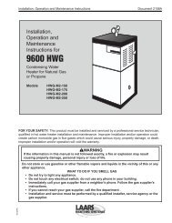
The air filter is normally located in the<br />
blower compartment (See Fig. 2) or in<br />
the factory-supplier filter cabinet attached<br />
to the side or bottom of the<br />
blower cabinet. If air filter has been installed<br />
in another location, contact your<br />
dealer for instructions. To inspect,<br />
clean, and/or replace the air filter(s),<br />
follow these steps:<br />
1. Turn off electrical supply to <strong>furnace</strong>.<br />
(See Fig. 17)<br />
2. Remove door/access panel<br />
• AIR FILTER(S) LOCATED IN<br />
BLOWER COMPARTMENT<br />
Remove control and blower access<br />
doors. (See Fig. 8)<br />
• AIR FILTER LOCATED IN FIL-<br />
TER CABINET<br />
Remove filter cabinet door (See<br />
Fig. 24 and 25)<br />
NOTE: It will be necessary to remove 1<br />
thumbscrew.<br />
20<br />
21<br />
3. Remove air filter from <strong>furnace</strong>.<br />
• AIR FILTER LOCATED IN<br />
BLOWER COMPARTMENT:<br />
a. Slide filter retainer sideways until<br />
it is free of latch. (See Fig. 20)<br />
b. Gently remove air filter and carefully<br />
turn the dirty side up (if dirty)<br />
to avoid spilling dirt from the filter.<br />
(see Fig. 21)<br />
• AIR FILTER LOCATED IN FIL-<br />
TER CABINET:<br />
a. Slide air filter out of <strong>furnace</strong>.<br />
Keep dirty side up (if dirty) to avoid<br />
spilling dirt. (See Fig. 26 and 27)<br />
22<br />
4. Inspect the filter. If torn, replace it.<br />
NOTE: If washable filter that was<br />
shipped with the <strong>furnace</strong> has been replaced<br />
by:<br />
a) Factory specified disposable media<br />
filter – Do not clean. If dirty, replace<br />
only with media filter having<br />
the same part number and size. Install<br />
with airflow direction arrow<br />
pointing towards blower.<br />
b) Electronic air cleaner (EAC) – Refer<br />
to EAC owner’s Manual for<br />
maintenance information.<br />
5. Wash filter (if dirty) in sink, bathtub,<br />
or outside with a garden hose.<br />
Always use cold tap water. A mild<br />
liquid detergent may be used if necessary.<br />
Spray water through filter in<br />
the opposite direction of airflow.<br />
Allow filter to dry.<br />
6. Reinstall clean air filter<br />
7. Reinstall filter retainer (for blower<br />
compartment locations only)<br />
8. Replace control and blower doors<br />
(See Fig. 13 and 22) or filter cabinet<br />
door (Fig. 28 and 29)<br />
9. Turn on electrical supply to <strong>furnace</strong><br />
(see Fig. 18).<br />
NOTE: If side return ducts are used,<br />
2 filters may be required in some<br />
models. The procedure listed above<br />
may be used to remove side filters.<br />
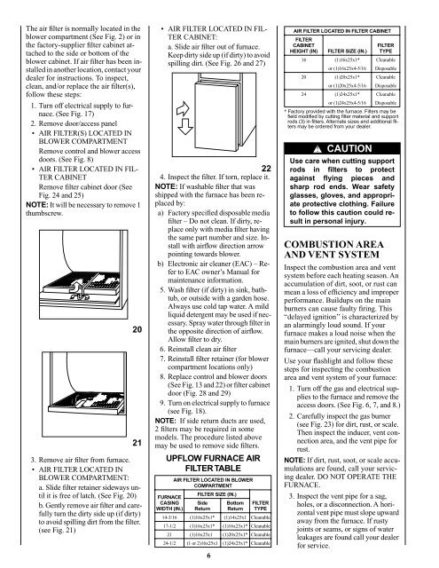
UPFLOW FURNACE AIR<br />
FILTER TABLE<br />
FURNACE<br />
CASING<br />
WIDTH (IN.)<br />
AIR FILTER LOCATED IN BLOWER<br />
COMPARTMENT<br />
FILTER SIZE (IN.)<br />
Side<br />
Return<br />
6<br />
Bottom<br />
Return<br />
FILTER<br />
TYPE<br />
14-3/16 (1)16x25x1* (1)14x25x1 Cleanable<br />
17-1/2 (1)16x25x1* (1)16x25x1* Cleanable<br />
21 (1)16x25x1* (1)20x25x1* Cleanable<br />
24-1/2 (1 or 2)16x25x1 (1)24x25x1* Cleanable<br />
AIR FILTER LOCATED IN FILTER CABINET<br />
FILTER<br />
CABINET<br />
HEIGHT (IN) FILTER SIZE (IN.)<br />
* Factory provided with the <strong>furnace</strong>. Filters may be<br />
field modified by cutting filter material and support<br />
rods (3) in filters. Alternate sizes and additional filters<br />
may be ordered from your dealer.<br />
COMBUSTION AREA<br />
AND VENT SYSTEM<br />
FILTER<br />
TYPE<br />
16 (1)16x25x1* Cleanable<br />
or (1)16x25x4-5/16 Disposable<br />
20 (1)20x25x1* Cleanable<br />
or (1)20x25x4-5/16 Disposable<br />
24 (1)24x25x1* Cleanable<br />
or (1)24x25x4-5/16 Disposable<br />
!<br />
CAUTION<br />
Use care when cutting support<br />
rods in filters to protect<br />
against flying pieces and<br />
sharp rod ends. Wear safety<br />
glasses, gloves, and appropriate<br />
protective clothing. Failure<br />
to follow this caution could result<br />
in personal injury.<br />
Inspect the combustion area and vent<br />
system before each heating season. An<br />
accumulation of dirt, soot, or rust can<br />
mean a loss of efficiency and improper<br />
performance. Buildups on the main<br />
burners can cause faulty firing. This<br />
“delayed ignition’’ is characterized by<br />
an alarmingly loud sound. If your<br />
<strong>furnace</strong> makes a loud noise when the<br />
main burners are ignited, shut down the<br />
<strong>furnace</strong>—call your servicing dealer.<br />
Use your flashlight and follow these<br />
steps for inspecting the combustion<br />
area and vent system of your <strong>furnace</strong>:<br />
1. Turn off the <strong>gas</strong> and electrical supplies<br />
to the <strong>furnace</strong> and remove the<br />
access doors. (See Fig. 6, 7, and 8.)<br />
2. Carefully inspect the <strong>gas</strong> burner<br />
(see Fig. 23) for dirt, rust, or scale.<br />
Then inspect the inducer, vent connection<br />
area, and the vent pipe for<br />
rust.<br />
NOTE: If dirt, rust, soot, or scale accumulations<br />
are found, call your servicing<br />
dealer. DO NOT OPERATE THE<br />
FURNACE.<br />
3. Inspect the vent pipe for a sag,<br />
holes, or a disconnection. A horizontal<br />
vent pipe must slope upward<br />
away from the <strong>furnace</strong>. If rusty<br />
joints or seams, or signs of water<br />
leakages are found call your dealer<br />
for service.