69-0653 - MagicStat CT3200 Programmable Thermostat ... - Geisel
69-0653 - MagicStat CT3200 Programmable Thermostat ... - Geisel
69-0653 - MagicStat CT3200 Programmable Thermostat ... - Geisel
You also want an ePaper? Increase the reach of your titles
YUMPU automatically turns print PDFs into web optimized ePapers that Google loves.
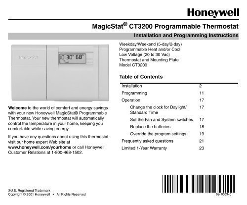
<strong>MagicStat</strong> ® <strong>CT3200</strong> <strong>Programmable</strong> <strong>Thermostat</strong><br />
Installation and Programming Instructions<br />
Weekday/Weekend (5-day/2-day)<br />
<strong>Programmable</strong> Heat and/or Cool<br />
Low Voltage (20 to 30 Vac)<br />
<strong>Thermostat</strong> and Mounting Plate<br />
Model <strong>CT3200</strong><br />
Table of Contents<br />
Welcome to the world of comfort and energy savings<br />
with your new Honeywell <strong>MagicStat</strong>® <strong>Programmable</strong><br />
<strong>Thermostat</strong>. Your new thermostat will automatically<br />
control the temperature in your home, keeping you<br />
comfortable while saving energy.<br />
If you have any questions about using this thermostat,<br />
visit our home expert Web site at<br />
www.honeywell.com/yourhome or call Honeywell<br />
Customer Relations at 1-800-468-1502.<br />
Installation 2<br />
Programming 11<br />
Operation 17<br />
Change the clock for Daylight/ 17<br />
Standard Time<br />
Set the Fan and System switches 17<br />
Replace the batteries 18<br />
Override the program settings 19<br />
Frequently asked questions 21<br />
Limited 1-Year Warranty 23<br />
®U.S. Registered Trademark<br />
Copyright © 2001 Honeywell • All Rights Reserved<br />
<strong>69</strong>- <strong>0653</strong>- 6
Fig. 1<br />
MERCURY<br />
SWITCH<br />
Recycling <strong>Thermostat</strong><br />
If you are removing an old thermostat that contains mercury in a<br />
sealed tube (Fig. 1), do not place the old thermostat in the trash.<br />
Contact your local waste management authority for instructions<br />
regarding recycling and the proper disposal of the old thermostat.<br />
M3701<br />
Installation<br />
Verify that you have the right thermostat<br />
Make sure that the <strong>CT3200</strong> is the right thermostat for your heating/cooling system. Read the compatibility chart below to<br />
determine which system you have. If your system is not compatible with the <strong>CT3200</strong>, the table recommends an alternate<br />
Honeywell model. If you are unsure what type of thermostat is right for your system, visit us on the Web at<br />
www.honeywell.com/yourhome or call Honeywell Customer Relations at 1-800-468-1502.<br />
Heating/Cooling System<br />
Conventional<br />
Single stage systems that include warm air furnaces and hot water.<br />
Electric Baseboard<br />
Electric powered heating strips located just above the floor, usually 120 to 240 volts.<br />
Steam<br />
A steam boiler with radiator heat.<br />
Heat Pump<br />
Heating and cooling are produced from the same outdoor unit (compressor) with no<br />
auxiliary or backup heat.<br />
Multistage Heat Pump<br />
Heating and cooling are produced from the same outdoor unit (compressor) with<br />
auxiliary or backup heat.<br />
Multistage Conventional<br />
A heating or cooling system with more than one stage.<br />
Compatible<br />
with <strong>CT3200</strong>?<br />
Yes<br />
No<br />
No<br />
No<br />
No<br />
No<br />
Alternate<br />
model<br />
CT1950 for<br />
240 volts<br />
CT3600<br />
CT3600<br />
CT3611<br />
See your<br />
contractor<br />
2 INSTALLATION <strong>69</strong>-<strong>0653</strong>-6
Step 1. Prepare for installation<br />
a. Carefully unpack your new thermostat. Save your receipt and make sure you have the following parts:<br />
• <strong>Thermostat</strong> and mounting plate<br />
• Labels<br />
b. Gather the needed tools and supplies listed below.<br />
• Screws and anchors<br />
• Installation and Programming Instructions<br />
Required tools and supplies<br />
• Two AA alkaline batteries. Honeywell recommends Energizer®<br />
batteries.<br />
• Screwdriver<br />
• Hand or power drill with 3/16-inch or 7/32-inch drill bit<br />
• Pencil<br />
Optional tools<br />
• Wire cutter/stripper or sharp knife<br />
• Level<br />
• Electrical tape<br />
c. Make sure that your heating and cooling systems are working properly. If there is a problem with either system, call a<br />
heating/air conditioning contractor—the problem may persist after you install the new thermostat.<br />
IMPORTANT: To avoid damaging the compressor in the air conditioner, do not operate the cooling system when the<br />
temperature outdoors is below 50°F (10°C).<br />
<strong>69</strong>-<strong>0653</strong>-6 INSTALLATION 3
Step 2. Remove the old thermostat<br />
Fig. 2<br />
Fig. 3<br />
Fig. 4<br />
WIRES THROUGH<br />
WALL OPENING<br />
M20133<br />
M20140<br />
M19086<br />
a. Turn off power to the heating/cooling system, either at the<br />
furnace or at the fuse/circuit breaker panel.<br />
b. Remove the cover of your old thermostat (Fig. 2).<br />
c. Unscrew and remove the old thermostat’s mounting plate from<br />
the wall, but do not disconnect the wires.<br />
d. Inspect the old thermostat wiring. If the wiring meets any of<br />
the following conditions, see the special wiring<br />
instructions on page 9.<br />
• The old thermostat is a clock thermostat with wires attached<br />
to the C or C1 terminals.<br />
• The old thermostat has 6 or more wires, excluding wires<br />
attached to C or C1 terminals.<br />
• The old thermostat has 3 wires.<br />
• There are 5 wires connected to the old thermostat.<br />
• There are extra wires that are not connected to the old<br />
thermostat.<br />
e. Using the enclosed labels, mark the wires with the letter of the<br />
terminal that it is attached to on the old thermostat (Fig. 3). Do<br />
not label the wires by color.<br />
If the labels do not match the letters on the old thermostat<br />
terminals, see the wiring cross reference table on page 10.<br />
f. Disconnect the wires from the old thermostat and wrap the<br />
wires around a pencil to keep them from falling back into the<br />
wall.<br />
Note: Remember, if your old thermostat contains mercury, you<br />
must recycle it. See page 2 for more recycling information.<br />
✓ Check your progress<br />
Your wall should now look like Fig. 4.<br />
4 INSTALLATION <strong>69</strong>-<strong>0653</strong>-6
Step 3. Install the mounting plate<br />
Fig. 5<br />
Fig. 6<br />
Fig. 7<br />
M20139<br />
M20129<br />
a. Separate the mounting plate from the thermostat using a coin,<br />
as shown in Fig 5.<br />
b. Position the mounting plate on the wall. Be sure the mounting<br />
plate sits flush against the wall and none of the wires are<br />
trapped behind it.<br />
c. Level the mounting plate and use a pencil to mark the center of<br />
the mounting plate’s screw holes.<br />
d. Remove the mounting plate and drill holes at the locations you<br />
marked.<br />
• For drywall, drill two 3/16 inch holes.<br />
• For plaster or wood, drill two 7/32 inch holes.<br />
e. If installing in drywall, gently tap the anchors that were provided<br />
into the drilled holes until they are flush with the wall.<br />
f. Reposition the mounting plate over the holes, pull the wires<br />
through the wiring opening, and loosely insert the mounting<br />
screws into each of the drilled holes or anchors (Fig. 6).<br />
g. Make sure the mounting plate is level and tighten the mounting<br />
screws.<br />
✓ Check your progress<br />
The mounting plate is now mounted on the wall and should look like<br />
Fig. 7.<br />
Y<br />
Rc<br />
G<br />
R<br />
W<br />
M20128<br />
<strong>69</strong>-<strong>0653</strong>-6 INSTALLATION 5
Step 4. Set the thermostat for your type of heating system<br />
Fig. 8<br />
DISPLAY F<br />
DISPLAY C<br />
C–IN<br />
C–OUT<br />
1 TURN<br />
FOR HIGH EFFICIENCY FURNACE (90%+ AFUE)<br />
ADJUST: SCREW A–OUT ONE TURN<br />
SCREW B–IN<br />
FUEL SWITCH – F POSITION<br />
FUEL SWITCH<br />
F<br />
E<br />
FUEL SWITCH<br />
HEATING<br />
SYSTEM TYPE<br />
THERMOSTAT BACK<br />
A C<br />
B D<br />
SELECTING ºF OR ºC<br />
ADJUST SCREWS THROUGH HOLES<br />
TO SELECT OPERATION DESIRED<br />
FUEL SWITCH<br />
HEATING SYSTEM POSITION<br />
WARM AIR<br />
FURNACE<br />
HOT WATER<br />
BOILER<br />
ELECTRIC<br />
FURNACE<br />
W Y G<br />
R<br />
A–IN B–IN<br />
A–OUT B–IN<br />
1 TURN<br />
A–IN B–OUT<br />
1 TURN<br />
F<br />
F<br />
E<br />
Rc<br />
M20145<br />
IMPORTANT: Setting your thermostat correctly for your type of<br />
heating system allows it to maintain accurate temperature control,<br />
minimize swings in the temperature of the room, and efficiently run<br />
the fan.<br />
a. Use the FUEL SWITCH on the back of the thermostat to set<br />
your new thermostat for the type of fuel that your heating<br />
system uses: F–gas or oil, or E–electricity.<br />
Note: This setting enables proper fan operation.<br />
b. Use the A and B screws on the back of the thermostat to set<br />
your new thermostat for your type of heating system. See the<br />
Heating System Table on the next page to find the correct<br />
settings.<br />
Note: These screws are factory-set for a warm air, gas, or oil<br />
heating system.<br />
c. The thermostat is set to display the temperature in degrees<br />
Fahrenheit (°F). If you want to display the temperature in<br />
degrees Celsius (°C), adjust screw C out one turn.<br />
d. You can install the batteries and program your thermostat now,<br />
or you can wait until the thermostat is mounted on the wall. To<br />
install the batteries, see the instructions on page 8. To program<br />
the thermostat, see the instructions that begin on page 12.<br />
6 INSTALLATION <strong>69</strong>-<strong>0653</strong>-6
Heating System Table<br />
Note: Setting the screw “out one turn” means turning the screw 360° counter-clockwise, or one complete turn.<br />
Type of system Screws A and B Fuel switch<br />
Warm air, gas, or oil heating system with an efficiency rating under 90%.<br />
(The furnace efficiency rating should be on the furnace.)<br />
High-efficiency furnace such as a 90% or greater AFUE (Average Fuel<br />
Utilization Efficiency) unit<br />
Hot water boiler<br />
Electric furnace<br />
Use factory setting<br />
A–leave in<br />
B–leave in<br />
A–out one turn<br />
B–leave in<br />
A–out one turn<br />
B–leave in<br />
A–leave in<br />
B–out one turn<br />
F<br />
F<br />
F<br />
E<br />
Step 5. Wire the thermostat terminals<br />
Fig. 9<br />
Fig. 10<br />
5/16 in.<br />
(8 mm)<br />
STRIP<br />
INSERT<br />
STRAIGHT<br />
UNDER<br />
SCREW HEAD<br />
R<br />
G<br />
Y<br />
W<br />
M20125<br />
a. Hold the thermostat as shown in Fig. 9.<br />
b. Using the labels on the wires, match the letter of your old<br />
thermostat wire with the corresponding terminal on the back of<br />
your new thermostat.<br />
Note: If the letters on the old thermostat terminals do not match<br />
the letters on the new thermostat terminals, you might not need<br />
to connect all of the old wires to the new thermostat. See the<br />
special wiring instructions on page 9 for details.<br />
c. Loosen the terminal screws and slip each wire beneath its<br />
matching terminal (Fig 10).<br />
d. Securely tighten the terminals.<br />
END OF WIRE<br />
VISIBLE HERE<br />
M20126<br />
<strong>69</strong>-<strong>0653</strong>-6 INSTALLATION 7
Step 6. Mount the thermostat<br />
Fig. 11 Fig. 12<br />
a. Align the tabs at the top of the thermostat with the tabs at the<br />
top of the mounting plate (Fig. 11).<br />
b. Press the lower edge of the case to latch the bottom of the<br />
thermostat (Fig. 12).<br />
M20130<br />
M20131<br />
Step 7. Install the batteries<br />
Fig. 13<br />
Fig. 14<br />
M1719C<br />
REMOVING<br />
BATTERY<br />
DOOR<br />
IMPORTANT: Batteries must be installed for programming and<br />
operation of the thermostat and heating/cooling system.<br />
Honeywell recommends using Energizer® batteries.<br />
a. Make sure that the System switch is set in the OFF position.<br />
b. Using a coin, open the battery door as shown in Fig. 13.<br />
c. Install the batteries.<br />
Make sure that the positive and negative terminals are oriented<br />
correctly as marked inside the battery case.<br />
d. Replace the battery door.<br />
e. Remove the clear plastic label from the digital display.<br />
✓ Check your progress<br />
When the batteries are installed correctly, the digital display flashes<br />
all entries once, then begins to flash a default time and the current<br />
temperature (Fig. 14). The flashing continues until you begin to<br />
program the thermostat.<br />
You are now ready to program the thermostat. Go to page 12.<br />
8 INSTALLATION <strong>69</strong>-<strong>0653</strong>-6
Special wiring instructions<br />
A clock thermostat with C or C1 terminals<br />
A clock thermostat has one or two extra wires attached to the C or C1 terminals that allow the clock to operate. These<br />
wires are not used during the installation of your new 3200 thermostat and must be insulated from each other to avoid<br />
damaging your electrical circuit.<br />
a. Make sure that power to the heating/cooling system is turned off.<br />
b. Locate the wires that are connected to the clock terminals marked C or C1.<br />
c. As you disconnect the wires, do not allow these wires to touch.<br />
d. Wrap the wires separately, using electrical tape to insulate the wires.<br />
e. Place the wires where they will not interfere with the operation of the new thermostat.<br />
You will not connect these wires to your 3200 thermostat.<br />
f. Continue with the installation as instructed on page 4 at step 2e.<br />
Six or more wires<br />
If your old thermostat has six or more wires (excluding clock wires attached to the C or C1 terminals), your heating/cooling<br />
system is most likely a variation of a heat pump or multistage system. Your 3200 thermostat will NOT work with such<br />
systems and should be returned to the place of purchase. See the compatibility table on page 2 for information about which<br />
programmable thermostat WILL work with your system.<br />
Three thermostat wires<br />
If you have three wires for heating only and can operate the fan using the fan ON switch, the 3200 thermostat will work with<br />
your system. Continue the installation procedure on page 4, step 2e.<br />
If you have a three-wire heating-only system and cannot operate the fan using the fan ON switch, the 3200 thermostat will<br />
probably NOT work with your system. Contact your heating contractor for installation assistance.<br />
Wires that are not connected to the old thermostat<br />
If there are extra wires that do not connect to your old thermostat, do not label them. You will not connect these wires to<br />
your new thermostat. Tape off the wires with electrical tape and place them where they will not interfere with the operation<br />
of the new thermostat. Continue the installation procedure on page 4, step 2e.<br />
<strong>69</strong>-<strong>0653</strong>-6 INSTALLATION 9
Five wires connected to the old thermostat<br />
Your new thermostat has a factory-installed metal jumper between the R and Rc terminals (Fig. 15). Remove the jumper<br />
before wiring the R and Rc terminals.<br />
JUMPER (FACTORY-<br />
INSTALLED). REMOVE<br />
IF 5-WIRE SYSTEM<br />
Fig. 15<br />
R R c<br />
W Y G<br />
M20127<br />
Old thermostat terminals that do not match new thermostat terminals<br />
Use the table below to wire the new thermostat.<br />
Old thermostat<br />
terminal<br />
Connect to new<br />
thermostat terminal<br />
Description<br />
R, RH, 4, V R* Power<br />
Rc, R Rc* Power for cooling<br />
W, W 1 , H W Heat<br />
Y, Y 1 , M Y Cooling<br />
G, F G Fan<br />
O<br />
Do not continue Changeover in cool (O terminal) or changeover in heat (B terminal).<br />
B<br />
installation<br />
You have a single stage heat pump or zoning system. See page 2 for an<br />
alternate thermostat model.<br />
C, X, B Do not connect Transformer common.<br />
W 2 , H 2<br />
Y 2<br />
Do not continue<br />
installation.<br />
Second stage heat (W 2 , H 2 ) or second stage cooling (Y 2 ).<br />
You have a multistage heating/cooling system. See page 2 for an alternate<br />
thermostat model.<br />
*Remove factory-installed jumper between R and Rc terminals in 5-wire systems.<br />
10 INSTALLATION <strong>69</strong>-<strong>0653</strong>-6
Programming<br />
Faceplate illustration and descriptions<br />
Fig. 16<br />
7 8<br />
Descriptions<br />
6<br />
5<br />
4<br />
3<br />
Set<br />
clock/Day<br />
AM<br />
PM<br />
SET<br />
MO TU WE TH FR SA SU<br />
WAKE LEAVE RETURN SLEEP<br />
Time<br />
Ahead<br />
Temp<br />
Warmer<br />
SYSTEM ON<br />
TEMPORARY<br />
Run<br />
Program<br />
9<br />
10<br />
11<br />
12<br />
1 Fan switch–Selects automatic fan operation or fan on<br />
(page 17)<br />
2 Set Schedule–Puts the thermostat into programming<br />
mode (page 14)<br />
3 Set Clock/Day–Sets the clock and day (page 12)<br />
4 Time Ahead and Back–Sets the time ahead and<br />
back (page 12)<br />
2<br />
Set<br />
Schedule<br />
Back<br />
Cooler<br />
Hold<br />
Temp<br />
13<br />
5 Program periods–Current program period or period<br />
being programmed (page 13)<br />
1<br />
Fan<br />
Auto On<br />
System<br />
Cool Off Heat<br />
14<br />
6 Day of the week–Current day or day being<br />
programmed<br />
7 Time–Current time or program time<br />
M20141<br />
8 Temperature–Room temperature or programmed<br />
temperature<br />
9 SYSTEM ON–An arrow displays when the heating/<br />
cooling system is running (page 16)<br />
10 TEMPORARY–An arrow displays when a temporary<br />
override is made to the program (page 19)<br />
11 Temp Warmer and Cooler–Sets the temperature<br />
warmer and cooler (page 14)<br />
12 Run Program–Returns thermostat to normal<br />
operating mode<br />
13 Hold Temp–Holds a selected temperature (page 19)<br />
14 System switch–Selects Cool, Off, Heat (page 18)<br />
<strong>69</strong>-<strong>0653</strong>-6 PROGRAMMING 11
Step 1. Set the current time and day<br />
a. Press once.<br />
The time is displayed (Fig. 17).<br />
Fig. 17<br />
b. Press and hold or until the current time is<br />
displayed.<br />
c. Press again.<br />
The day is displayed (Fig. 18).<br />
Fig. 18<br />
d. Press and hold or until the current day is<br />
displayed.<br />
e. Press once.<br />
The current time and day and the current temperature are<br />
displayed (Fig. 19).<br />
Fig. 19<br />
Step 2. Learn about the programming features<br />
Your 3200 thermostat allows you to program schedules for both a heating season and a cooling season.<br />
• During the heating season, you will want to set the normal room temperature higher and the energy-saving<br />
temperature lower.<br />
• The reverse is true during the cooling season—the normal room temperature will be lower and the energy-saving<br />
temperature higher.<br />
For each season, you can set up to four program periods for the weekdays (Monday–Friday), and up to two program<br />
periods for the weekends (Saturday and Sunday). The program periods are defined on the next page.<br />
12 PROGRAMMING <strong>69</strong>-<strong>0653</strong>-6
Program period Description When available<br />
WAKE<br />
LEAVE<br />
RETURN<br />
SLEEP<br />
The time when you get up and get ready to leave your home.<br />
You can set the system at a comfortable temperature for this<br />
period.<br />
The time when you are regularly away from home. You can set<br />
up an energy-saving temperature for this period.<br />
The time between returning home and going to bed. You can<br />
set the system at a comfortable temperature for this period.<br />
The time when you are sleeping. You can set up an energysaving<br />
temperature for this period.<br />
Weekdays and weekend<br />
Weekdays only<br />
Weekdays only<br />
Weekdays and weekend<br />
Programming tips<br />
• You do not need to program times and temperatures for all program periods.<br />
If you decide not to program your thermostat, it will automatically control heating at 68°F (20°C), and cooling at 78°F<br />
(26°C), 24 hours a day.<br />
If you decide not to program weekend schedules, the temperature that is programmed for the weekday SLEEP<br />
schedule will remain in effect until the next program period, which begins on Monday morning.<br />
• The temperatures cannot be set any higher than 88°F (31°C) or any lower than 45°F (7°C).<br />
• When pressing the buttons, use the ball of your finger or a soft pencil eraser. Use of sharp fingernails or pencil points<br />
can damage the keypad.<br />
• If you make an error at any time during programming, press . Then press until you reach the program<br />
period where you left off.<br />
<strong>69</strong>-<strong>0653</strong>-6 PROGRAMMING 13
Step 3. Program the heating schedule<br />
a. Write in the times and temperatures that you want to program for your heating schedule.<br />
Heating<br />
Schedule<br />
Suggested<br />
Settings<br />
Weekday<br />
(Mon–Fri)<br />
Weekend<br />
(Sat–Sun)<br />
Program<br />
period<br />
WAKE LEAVE RETURN SLEEP<br />
Time 6:00 AM 8:00 AM 6:00 PM 10:00 PM<br />
Temp 70°F (21°C) 62°F (16.5°C) 70°F (21°C) 62°F (16.5°C)<br />
Time<br />
Temp<br />
Time<br />
Temp<br />
b. Set the System switch to HEAT.<br />
Fig. 20<br />
c. Press once.<br />
A blank schedule is displayed (Fig. 20).<br />
d. Set the Monday–Friday WAKE time by pressing or<br />
Fig. 21<br />
until the desired time is displayed (Fig. 21).<br />
e. Set the Monday–Friday WAKE temperature by pressing<br />
or until the desired temperature is<br />
displayed.<br />
f. Press to display a blank schedule for the next<br />
program period (Fig. 22) and repeat steps d. through f. for<br />
each weekday program period.<br />
Fig. 22<br />
14 PROGRAMMING <strong>69</strong>-<strong>0653</strong>-6
g. Press until the weekend schedule is displayed<br />
(Fig. 23).<br />
h. Set the Saturday and Sunday WAKE time by pressing<br />
or until the desired time is displayed.<br />
i. Set the Saturday and Sunday WAKE temperature by<br />
Fig. 23<br />
Fig. 24<br />
pressing or until the desired temperature<br />
is displayed (Fig. 24).<br />
j. Press again to display a blank schedule for the<br />
SLEEP program period and repeat steps h. through j. to set<br />
the program.<br />
k. Press to start the program.<br />
Step 4. Program the cooling schedule<br />
a. Write in the times and temperatures that you want to program for your cooling schedule.<br />
Cooling<br />
Schedule<br />
Suggested<br />
Settings<br />
Weekday<br />
(Mon–Fri)<br />
Weekend<br />
(Sat–Sun)<br />
Program<br />
period<br />
WAKE LEAVE RETURN SLEEP<br />
Time 6:00 AM 8:00 AM 6:00 PM 10:00 PM<br />
Temp 78°F (25.5°C) 85°F (29.5°C) 78°F (25.5°C) 82°F (28°C)<br />
Time<br />
Temp<br />
Time<br />
Temp<br />
<strong>69</strong>-<strong>0653</strong>-6 PROGRAMMING 15
. Set the System switch to COOL.<br />
c. Repeat steps 3c. through 3k. to program the weekday and weekend cooling schedule.<br />
Step 5. Check out the system<br />
Verify that your heating system works<br />
a. Set the System switch to HEAT, and the Fan switch to<br />
AUTO.<br />
b. Press until the setting is 10°F (6°C) above room<br />
temperature (Fig. 25).<br />
Your heating system should start and the fan should run<br />
after a short delay.<br />
Fig. 25<br />
c. Press until the setting is 10°F (6°C) below room<br />
temperature.<br />
Your heating system should shut off.<br />
Verify that your cooling system works<br />
IMPORTANT: To avoid damaging the compressor in the air<br />
conditioner, do not operate the cooling system when the<br />
temperature outdoors is below 50°F (10°C).<br />
d. Set the System switch to COOL, and the Fan switch to<br />
AUTO.<br />
Fig. 26<br />
e. Press until the setting is 10°F (6°C) below room<br />
temperature (Fig. 26).<br />
Your cooling system and fan should start.<br />
Note: When the cooling setting is changed, the thermostat<br />
may delay up to 5 minutes before turning on the air<br />
conditioner. This delay protects the compressor.<br />
16 PROGRAMMING <strong>69</strong>-<strong>0653</strong>-6
f. Press until the setting is 10°F (6°C) above room<br />
temperature.<br />
Your cooling system and fan should stop.<br />
g. Set the System switch to OFF and the Fan switch to AUTO.<br />
The cooling system and fan should be off.<br />
Operation<br />
Change the clock for Daylight/Standard time<br />
a. Press once.<br />
The time is displayed.<br />
b. Press and hold or until the correct time is displayed.<br />
c. Press once.<br />
The current time and day and the current temperature are displayed.<br />
Set the Fan and System switches<br />
The switches on the bottom of the thermostat faceplate (Fig. 16 page 11) control the operation of your fan and the heating<br />
and cooling system. Set the Fan switch first and then set the System switch.<br />
Switch Setting Result<br />
Fan Auto A single-speed fan turns on automatically with the air conditioner or furnace.<br />
A two-speed fan usually runs on high with the air conditioner and on low with the furnace.<br />
Auto is the normal setting for most homes.<br />
On The fan runs continuously. Use this setting for improved air circulation during special occasions<br />
or for more efficient air cleaning.<br />
Note: In a heat-only system, the fan runs continuously only if the fan wire has been connected to<br />
the G terminal on the back of the thermostat.<br />
<strong>69</strong>-<strong>0653</strong>-6 OPERATION 17
Switch Setting Result<br />
System Cool The thermostat controls your air conditioning system.<br />
Off Both the heating and air conditioning systems are off.<br />
Heat The thermostat controls your heating system.<br />
Replace the batteries<br />
As the batteries run low, your thermostat shows the following in the digital display:<br />
If you see:<br />
Batteries are: You should:<br />
Flashing “bAt Lo” Low Replace the batteries as soon as possible, within the month.<br />
Steady “bAt Lo” Almost dead Replace the batteries immediately. Your heating/cooling system is not operating.<br />
Blank display Dead Replace the batteries immediately. Your heating/cooling system is not operating.<br />
a. Make sure that the System switch is set in the OFF position.<br />
b. Open the battery door.<br />
c. Press on the left side of the batteries to remove them.<br />
d. Install the new batteries.<br />
Make sure that the positive and negative terminals are oriented correctly as marked inside the battery case.<br />
Note: If you insert the new batteries within 20–30 seconds of removing the old ones, you will not have to reprogram<br />
the thermostat. However, if the display is blank, the batteries are dead or incorrectly installed and you will have to<br />
reprogram. See page 12 to begin reprogramming.<br />
e. Close the battery door and set the System switch to HEAT or COOL.<br />
Note: If “bAt Lo” continues to display after replacing the batteries, set the System switch to OFF, insert the batteries<br />
backwards, wait for five to ten seconds, and return the batteries to their correct orientation. Then see page 12 to begin<br />
reprogramming.<br />
IMPORTANT: Replace the batteries once a year to prevent the heating/cooling system from shutting down due to lack of<br />
battery power in the thermostat. If you are leaving home for longer than a month, change the batteries before leaving to<br />
prevent the system from shutting down due to lack of power.<br />
18 OPERATION <strong>69</strong>-<strong>0653</strong>-6
Override the program settings<br />
Note: Make sure the System switch is set to either HEAT or<br />
COOL before making any changes to the schedule.<br />
Change the temperature temporarily<br />
Press or until the desired temperature is<br />
displayed.<br />
An arrow is displayed indicating that the change is temporary<br />
(Fig. 27).<br />
Note: A temporary change to the temperature lasts for the<br />
current program period only. The heating/cooling schedule that<br />
you programmed resumes when the next scheduled program<br />
period is reached. To cancel the temporary change before the<br />
next scheduled program period, press .<br />
Fig. 27<br />
Hold a temperature indefinitely<br />
Use the Hold Temp feature when you want to maintain a<br />
constant temperature indefinitely, such as when you go on<br />
vacation.<br />
a. Press .<br />
“HLd” is displayed (Fig. 28).<br />
Fig. 28<br />
b. Press or until the desired temperature is<br />
displayed.<br />
Note: To cancel the hold, press .<br />
<strong>69</strong>-<strong>0653</strong>-6 OPERATION 19
Check the current programmed temperature<br />
Press to display the temperature that is programmed<br />
for the current program period. The SET indicator displays<br />
briefly along with the programmed temperature (Fig. 29). The<br />
display then returns to the room temperature.<br />
Fig. 29<br />
Check programs<br />
Press repeatedly to display the times and temperatures<br />
that you programmed.<br />
Press to resume the program.<br />
Cancel a program<br />
Fig. 30<br />
a. Press until the desired program is displayed (Fig<br />
30).<br />
b. Press and simultaneously.<br />
A blank program schedule is displayed and the program is<br />
canceled (Fig. 31).<br />
Fig. 31<br />
Change a program permanently<br />
Follow the steps for programming the heating schedule or<br />
programming the cooling schedule on pages 14 and 15.<br />
20 OPERATION <strong>69</strong>-<strong>0653</strong>-6
Frequently asked questions<br />
If...<br />
Then...<br />
Display will not come on • Make sure the batteries are fresh and installed correctly.<br />
• Set the System switch to OFF. Remove the batteries and then insert them<br />
backwards for five to ten seconds to reset the thermostat. Replace the<br />
batteries correctly. The display should come on.<br />
Temperature display will not go<br />
lower than 45°F (7°C) or higher<br />
than 88°F (31°C) during<br />
programming<br />
Display shows flashing or steady<br />
“bAt Lo”<br />
Temperature change occurs at the<br />
wrong times<br />
• You have reached the temperature limit. The setting range is 45°F–88°F<br />
(7°C–31°C).<br />
• The batteries are low; replace them as soon as possible. See page 18 for<br />
instructions.<br />
• If “bAt Lo” continues to display after replacing the batteries, set the System<br />
switch to OFF and insert the batteries backwards for five to ten seconds.<br />
Then replace the batteries correctly. The display should come on.<br />
• Check the program times for the period in question. Be sure that the AM and<br />
PM indications are correct. Make sure the current day and time are correct.<br />
Reprogram if necessary.<br />
Heating will not come on • Check that the System switch is set to HEAT.<br />
• Check the system fuse or circuit breaker and replace or reset if necessary.<br />
• Check for correct wiring and good connections.<br />
• If display is blank or displays “bAt Lo,” install fresh batteries.<br />
• Allow time for the furnace to heat up and the fan to come on before checking<br />
for heat at the register.<br />
• If the temperature setting is higher than the current room temperature and<br />
the SYSTEM ON arrow is displayed, the thermostat is operating correctly.<br />
Contact a heating contractor for assistance.<br />
<strong>69</strong>-<strong>0653</strong>-6 FREQUENTLY ASKED QUESTIONS 21
If...<br />
Cooling will not come on • Check that the System switch is set to COOL.<br />
• Check the system fuse or circuit breaker and replace or reset if necessary.<br />
• Check for correct wiring and good connections.<br />
• If display is blank or says “bAt Lo,” install fresh batteries.<br />
• The thermostat has a built-in time delay on cooling. Allow 5 to 10 minutes<br />
after changing the setting before the air conditioner starts.<br />
• If the temperature setting is lower than the current room temperature and the<br />
SYSTEM ON arrow is displayed, the thermostat is operating correctly.<br />
Contact an air conditioning contractor for assistance.<br />
The house is too warm or too cool<br />
The furnace cycles too frequently<br />
or the system cycle length is too<br />
short or too long<br />
The thermostat’s current setting<br />
does not match the display<br />
temperature to within plus or minus<br />
1°<br />
Then...<br />
• Press to check the current temperature setting.<br />
• If desired, change the temperature setting. See page 19 for instructions.<br />
• Adjust the screws on the back of the thermostat as instructed on page 7.<br />
• Plug the wiring hole in the wall behind the mounting plate with insulation to<br />
prevent drafts that might adversely affect thermostat operation.<br />
• Be aware that it is normal for the current setting and the displayed room<br />
temperature to differ on occasion.<br />
• During recovery from setback or setup, setting and displayed room<br />
temperatures may differ for up to 30 minutes after recovery period.<br />
Customer assistance<br />
For all questions concerning this thermostat, please read and follow the instructions. If you need additional assistance, call<br />
Honeywell Customer Relations at 1-800-468-1502, Monday–Friday, 7:00 AM–5:30 PM Central Time, or visit us at<br />
www.honeywell.com/yourhome. Before you call, please have the following information available:<br />
• <strong>Thermostat</strong> model number and serial code (located under the battery cover)<br />
• Type of heating/cooling system (hot water, warm air, oil, gas, etc.)<br />
• Number of wires connected to the thermostat<br />
NOTICE: This equipment is a Class B digital apparatus, which complies with Canadian Radio Interference Regulations, CRC c.1374.<br />
22 FREQUENTLY ASKED QUESTIONS <strong>69</strong>-<strong>0653</strong>-6
Limited warranty<br />
Honeywell warrants this product, excluding battery, to be free from defects in the workmanship or materials, under normal use and service,<br />
for a period of one (1) year from the date of purchase by the consumer. If, at any time during the warranty period, the product is defective<br />
or malfunctions, Honeywell shall repair or replace it (at Honeywell’s option) within a reasonable period of time.<br />
If the product is defective,<br />
(i) return it, with a bill of sale or other dated proof of purchase, to the retailer from which you purchased it, or<br />
(ii) package it carefully, along with proof of purchase (including date of purchase) and a short description of the malfunction, and mail it,<br />
postage prepaid, to the following address:<br />
Honeywell Inc. USA<br />
Honeywell Canada:<br />
Dock 4 — MN10-3860<br />
Honeywell Limited/Honeywell Limitée<br />
1885 Douglas Drive North 35 Dynamic Drive<br />
Golden Valley, MN 55422-3992 Scarborough, Ontario M1V 4Z9<br />
This warranty does not cover removal or reinstallation costs. This warranty shall not apply if it is shown by Honeywell that the defect or<br />
malfunction was caused by damage which occurred while the product was in the possession of a consumer.<br />
Honeywell’s sole responsibility shall be to repair or replace the product within the terms stated above. HONEYWELL SHALL NOT BE<br />
LIABLE FOR ANY LOSS OR DAMAGE OF ANY KIND, INCLUDING ANY INCIDENTAL OR CONSEQUENTIAL DAMAGES RESULTING,<br />
DIRECTLY OR INDIRECTLY, FROM ANY BREACH OF ANY WARRANTY, EXPRESS OR IMPLIED, OR ANY OTHER FAILURE OF THIS<br />
PRODUCT. Some states do not allow the exclusion or limitation of incidental or consequential damages, so this limitation may not apply to<br />
you.<br />
THIS WARRANTY IS THE ONLY EXPRESS WARRANTY HONEYWELL MAKES ON THIS PRODUCT. THE DURATION OF ANY<br />
IMPLIED WARRANTIES, INCLUDING THE WARRANTIES OF MERCHANTABILITY AND FITNESS FOR A PARTICULAR PURPOSE, IS<br />
HEREBY LIMITED TO THE ONE YEAR DURATION OF THIS WARRANTY. Some states do not allow limitations on how long an implied<br />
warranty lasts, so the above limitation may not apply to you.<br />
This warranty gives you specific legal rights, and you may have other rights which vary from state to state.<br />
If you have any questions concerning this warranty, please write our Customer Relations Center, Honeywell Inc., 1885 Douglas Dr. N.,<br />
Golden Valley, MN 55422-3992, or call 1-800-468-1502, Monday–Friday, 7:00 a.m. to 5:30 p.m., Central Time. In Canada, write Retail<br />
Products ON30 Honeywell Limited/Honeywell Limitée, 35 Dynamic Drive, Scarborough, Ontario M1V 4Z9.<br />
<strong>69</strong>-<strong>0653</strong>-6 FREQUENTLY ASKED QUESTIONS 23
Home and Building Control<br />
Honeywell<br />
1985 Douglas Drive North<br />
Golden Valley, MN 55422<br />
<strong>69</strong>-<strong>0653</strong>-6 Rev. 9-01<br />
Home and Building Control<br />
Honeywell Limited–Honeywell Limitée<br />
35 Dynamic Drive<br />
Scarborough, Ontario<br />
M1V 4Z9<br />
Printed in the U.S.A.<br />
www.honeywell.com/yourhome


