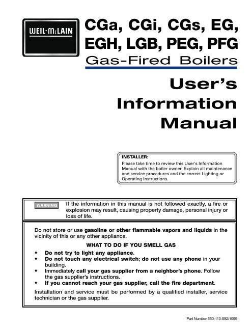
CGa, CGi, CGs, EG, EGH, LGB, PEG, PFG - Geisel
CGa, CGi, CGs, EG, EGH, LGB, PEG, PFG - Geisel
CGa, CGi, CGs, EG, EGH, LGB, PEG, PFG - Geisel

Create successful ePaper yourself
Turn your PDF publications into a flip-book with our unique Google optimized e-Paper software.
<strong>CGa</strong>, <strong>CGi</strong>, <strong>CGs</strong>, <strong>EG</strong>,<br />
<strong>EG</strong>H, <strong>LGB</strong>, P<strong>EG</strong>, <strong>PFG</strong><br />
Gas-Fired Boilers<br />
User’s<br />
Information<br />
Manual<br />
If the information in this manual is not followed exactly, a fire or<br />
explosion may result, causing property damage, personal injury or<br />
loss of life.<br />
Do not store or use gasoline or other flammable vapors and liquids in the<br />
vicinity of this or any other appliance.<br />
WHAT TO DO IF YOU SMELL GAS<br />
• Do not try to light any appliance.<br />
Do not touch any electrical switch; do not use any phone in your<br />
building.<br />
Immediately call your gas supplier from a neighbor’s phone. Follow<br />
the gas supplier’s instructions.<br />
If you cannot reach your gas supplier, call the fire department.<br />
Installation and service must be performed by a qualified installer, service<br />
technician or the gas supplier.<br />
Part Number 550-110-592/1099
How to use this<br />
manual . . .<br />
Hazard definitions<br />
Boiler service and<br />
maintenance<br />
Please read this page first<br />
To . . . Read/use . . . Pages . . .<br />
Learn<br />
precautions<br />
Prevent air<br />
contamination<br />
Identify boiler<br />
components<br />
Maintain<br />
boiler<br />
Start — or —<br />
Shutdown<br />
boiler<br />
Troubleshoot<br />
common<br />
problems<br />
Warnings and definitions 1, 2, and 3<br />
Read list of air contaminants you must avoid. If<br />
found, either remove products permanently<br />
or isolate boiler and provide outside combustion<br />
air.<br />
The illustration on page 4 or 5, will show you the<br />
location of the main components.<br />
Set up a plan for maintaining the boiler using<br />
the schedule included in this manual.<br />
Schedule an annual start-up by a qualified service<br />
technician before every heating season.<br />
Use the Lighting/Operating instruction sheet<br />
for the gas valve installed on your boiler. Ask<br />
your service technician if you are unsure which<br />
one.<br />
Use the common problems/solutions table to<br />
resolve typical heating system/boiler problems.<br />
The following defined terms are used throughout this manual to bring attention to the presence<br />
of hazards of various risk levels or to important information concerning the life of the product.<br />
Indicates presence of hazards that will cause severe personal injury, death<br />
or substantial property damage.<br />
Indicates presence of hazards that can cause severe personal injury, death<br />
or substantial property damage.<br />
Indicates presence of hazards that will or can cause minor personal injury<br />
or property damage.<br />
Indicates special instructions on installation, operation or maintenance<br />
that are important but not related to personal injury or property damage.<br />
The User’s Information Manual provides information to the boiler owner/user for routine<br />
operation and maintenance and emergency shutdown. Detailed information on boiler<br />
installation, operation, start-up, service and parts is included in the Boiler Manual. The Boiler<br />
Manual is intended only for use by a qualified installer/service technician.<br />
2 Part Number 550-110-592/1099<br />
3<br />
4-5<br />
6-12<br />
12-22<br />
23
STOP!! — Read before proceeding<br />
Part Number 550-110-592/1099<br />
Failure to adhere to the guidelines on this page can result in severe personal injury, death or substantial<br />
property damage.<br />
Air contamination<br />
• To prevent potential of severe personal injury or death, check for products or<br />
areas listed in table at right before installing boiler. If any of these contaminants<br />
are found:<br />
remove contaminants permanently. — OR —<br />
isolate boiler and provide outside combustion air. See national,<br />
provincial or local codes for further information. — OR —<br />
for <strong>CGs</strong> boilers only — combustion air may be ducted from outside<br />
to the boiler air intake.<br />
Service and maintenance<br />
To avoid electric shock, disconnect electrical supply before performing<br />
maintenance.<br />
To avoid severe burns, allow boiler to cool before performing maintenance.<br />
You must maintain the boiler as outlined in the manual and have the boiler<br />
started up and serviced at least annually by a qualified service technician<br />
to ensure boiler/system reliability.<br />
Boiler operation<br />
Do not block flow of combustion or ventilation air to boiler. This boiler is<br />
equipped with a control which will automatically shut down the boiler should<br />
air or vent be blocked. If vent or air blockage is easily accessible and removable,<br />
remove it. The boiler should attempt to restart within an hour. If blockage is<br />
not obvious or cannot be removed, have the boiler and system checked by a<br />
qualified service technician.<br />
Should overheating occur or gas supply fail to shut off, do not turn off or<br />
disconnect electrical supply to pump. Instead, shut off the gas supply at a<br />
location external to the appliance.<br />
Do not use this boiler if any part has been under water. Immediately call a<br />
qualified service technician to inspect the boiler and to replace any part of the<br />
control system and any gas control, which has been under water.<br />
Have the building monitored when it is vacant for an extended period. Safety<br />
controls can shut down the boiler at any time. The loss of heat can result in<br />
significant damage due to freezing.<br />
Boiler water<br />
DO NOT use petroleum-based cleaning or sealing compounds in boiler system.<br />
Water seal deterioration will occur, causing leakage between sections and damage<br />
to heating system components. This can result in substantial property damage.<br />
DO NOT use "homemade cures" or "boiler patent medicines". Serious damage<br />
to boiler, personnel and/or property may result.<br />
Continual fresh makeup water will reduce boiler life. Mineral buildup in<br />
sections reduces heat transfer, overheats cast iron, and causes section failure.<br />
Addition of oxygen and other gases can cause internal corrosion. Leaks in boiler<br />
or piping must be repaired at once to prevent makeup water.<br />
Do not add cold water to hot boiler. Thermal shock can cause sections to<br />
crack.<br />
Products to avoid<br />
Spray cans containing chloro/fluorocarbons<br />
Permanent wave solutions<br />
Chlorinated waxes/cleaners<br />
Chlorine-based swimming pool chemicals<br />
Calcium chloride used for thawing<br />
Sodium chloride used for water softening<br />
Refrigerant leaks<br />
Paint or varnish removers<br />
Hydrochloric acid/muriatic acid<br />
Cements and glues<br />
Antistatic fabric softeners used in clothes<br />
dryers<br />
Chlorine-type bleaches, detergents, and<br />
cleaning solvents found in household<br />
laundry rooms<br />
Adhesives used to fasten building products<br />
and other similar products<br />
Areas likely to have<br />
contaminants<br />
Dry cleaning/laundry areas and establishments<br />
Swimming pools<br />
Metal fabrication plants<br />
Beauty shops<br />
Refrigeration repair shops<br />
Photo processing plants<br />
Auto body shops<br />
Plastic manufacturing plants<br />
Furniture refinishing areas and establishments<br />
New building construction<br />
Remodeling areas<br />
Garages with workshops<br />
3
Boiler components<br />
<br />
59210<br />
1 Gas valve<br />
2 Pilot burner<br />
3 Main burner<br />
4 Gas manifold/orifices<br />
5 Control module<br />
6 Inducer (<strong>CGi</strong> and <strong>CGs</strong> only)<br />
7 Vent damper (<strong>CGa</strong> only)<br />
8 Water temperature limit switch<br />
9 Transformer<br />
10 Spill switch (<strong>CGa</strong> only)<br />
11 Air pressure switch (<strong>CGi</strong> and <strong>CGs</strong> only)<br />
12 Rollout thermal fuse element<br />
15 Draft hood (<strong>CGa</strong> only)<br />
16 Circulator<br />
17 Relief valve<br />
18 Gauge (pressure or pressure/temperature)<br />
4 Part Number 550-110-592/1099<br />
59211
1 Gas valve<br />
2 Pilot burner<br />
3 Main burner<br />
4 Gas manifold/orifices<br />
5 Control module<br />
7 Vent damper<br />
9 Transformer<br />
10 Spill switch<br />
12 Rollout thermal fuse element<br />
13 Low water cutoff (steam boilers)<br />
14 Limit control(s)<br />
15 Draft hood<br />
16 Circulator<br />
18 Gauge (pressure or pressure/temperature)<br />
19 Gauge glass (steam only)<br />
Part Number 550-110-592/1099<br />
<br />
5
Maintain boiler using schedule below<br />
Service technician<br />
(covered in Boiler Manual — for use only by a<br />
qualified service technician)<br />
ANNNUAL START-UP<br />
Inspect:<br />
• Reported problems<br />
Service:<br />
Start-up:<br />
Boiler area<br />
Air openings<br />
Flue gas vent system<br />
Pilot and main burner flames<br />
Water piping<br />
Boiler heating surfaces<br />
Burners, base and inlet air box<br />
Oiled-bearing circulators<br />
Perform start-up per manual<br />
Check/test:<br />
Review:<br />
Gas piping<br />
Cold fill and operating pressures<br />
Air vents and air elimination<br />
Limit controls and cutoffs<br />
Expansion tank<br />
Boiler relief valve<br />
Review with owner<br />
Tankless water heater (<strong>EG</strong> and <strong>EG</strong>H only)<br />
If boiler is used to supply domestic hot water, limit<br />
control should be set to supply adequate hot water.<br />
Weil-McLain tankless heaters are rated at 200 °F boiler<br />
water temperature. To get rated output, set low limit at<br />
200 °F. Limit can be adjusted to meet system hot water<br />
Owner maintenance<br />
(see following pages for instructions)<br />
requirements. Differential can be set to 15 ° and adjusted<br />
to control level. Lowering the differential will cause a<br />
slight variation in water temperature but will decrease<br />
burner on-off cycling. High limit should be set at least<br />
20 ° above low limit.<br />
6 Part Number 550-110-592/1099<br />
Daily<br />
Monthly<br />
Check boiler area<br />
Check air openings<br />
Check boiler pressure/<br />
temperature gauge<br />
Check boiler interior piping<br />
Check venting system<br />
Check air vents<br />
Check boiler relief valve<br />
Check automatic air vents (if<br />
used)<br />
Periodically Test low water cutoff (if used)<br />
Every 6 months Operate relief valve<br />
End of season Shut down procedure
Part Number 550-110-592/1099<br />
<br />
User maintenance procedures<br />
Boiler must be serviced & maintained<br />
The boiler should be inspected and started annually, at<br />
the beginning of the heating season, only by a qualified<br />
service technician. In addition, the maintenance and<br />
care of the boiler designated on page 6 and explained<br />
on the following pages must be performed to assure<br />
maximum boiler efficiency and reliability. Failure to<br />
service and maintain the boiler and system could result<br />
in equipment failure, causing possible severe personal<br />
injury, death or substantial property damage.<br />
Component information<br />
Rollout thermal fuse element<br />
<strong>CGa</strong>, <strong>CGi</strong>, <strong>CGs</strong>, <strong>EG</strong>, <strong>EG</strong>H, P<strong>EG</strong> & <strong>PFG</strong>-5 only<br />
Cuts off gas flow should flame rollout occur. See<br />
Figure 1.<br />
Do not attempt to place boiler in operation if rollout<br />
thermal fuse element cuts off gas flow. Immediately<br />
call a service technician. Failure to do so can cause<br />
severe personal injury, death or substantial property<br />
damage.<br />
Spill switch<br />
<strong>CGa</strong>, <strong>EG</strong>, <strong>EG</strong>H, P<strong>EG</strong> & <strong>PFG</strong>-5 only<br />
Cuts off gas flow should vent system become blocked.<br />
See Figure 2.<br />
Do not attempt to place boiler in operation if spill<br />
switch cuts off gas flow. Immediately call a service<br />
technician. Failure to do so can cause severe personal<br />
injury, death or substantial property damage.<br />
Boiler area<br />
To prevent potential of severe personal injury, death<br />
or substantial property damage, eliminate all materials<br />
discussed below from the boiler vicinity. If found:<br />
Remove products immediately from the area. If<br />
they have been there for an extended period, call a<br />
qualified service technician to inspect the boiler and<br />
vent system for possible damage from acid<br />
corrosion.<br />
If products cannot be removed, immediately call a<br />
Figure 1<br />
Rollout thermal fuse element<br />
Figure 2<br />
Spill switch<br />
59202<br />
59201<br />
The following information<br />
provides detailed instructions for<br />
completing the maintenance items<br />
listed in the maintenance schedule,<br />
page 6. In addition to this<br />
maintenance, the boiler must be<br />
serviced and started up at the<br />
beginning of each heating season<br />
by a qualified service technician.<br />
❏ Check daily . . . . . . . . . . . . . . . . .<br />
qualified service technician to install an outside<br />
combustion air source for the boiler (if not already<br />
installed).<br />
1. Combustible/flammable materials — Do not store<br />
combustible materials, gasoline or any other<br />
flammable vapors or liquids near the boiler.<br />
Remove immediately if found.<br />
2. Air contaminants — See listing of contaminants<br />
on page 3.<br />
7
❏ Check daily . . . . . . . . . . . . . . . . .<br />
Pressure/temperature gauge<br />
or pressure gauge (steam)<br />
1. Water boilers — Make sure the pressure reading<br />
on the boiler pressure/temperature gauge does not<br />
exceed 24 psig. Higher pressure may indicate a<br />
problem with the expansion tank or gauge.<br />
2. Steam boilers — Make sure the pressure reading<br />
on the boiler pressure gauge does not exceed 15<br />
psig. Higher pressure indicates a problem with the<br />
gauge or limit control.<br />
3. Contact a qualified service technician if problem<br />
persists.<br />
Air openings<br />
1. Verify that combustion and ventilation air openings<br />
to the boiler room and/or building are open and<br />
unobstructed.<br />
2. <strong>CGs</strong> boilers — Verify that boiler vent discharge<br />
and air intake are clean and free of obstructions.<br />
Remove any debris on the air intake or flue exhaust<br />
openings.<br />
❏ Check monthly . . . . . . . . . . . . . . . .<br />
Boiler piping<br />
1. Visually inspect for leaks around piping, circulators,<br />
relief valve and other fittings. Immediately call a<br />
qualified service technician to repair any leaks.<br />
Have leaks fixed at once by a qualified service<br />
technician. Continual fresh makeup water will reduce<br />
boiler life. Minerals can build up in sections, reducing<br />
heat transfer, overheating cast iron, and causing section<br />
failure.<br />
Do not use petroleum-based cleaning or sealing<br />
compounds in boiler system. Severe damage to boiler<br />
and system components can occur, resulting in possible<br />
severe personal injury, death or substantial property<br />
damage.<br />
Venting system<br />
Failure to inspect the vent system as noted above and<br />
have them repaired by a qualified service technician<br />
can result in vent system failure, causing severe personal<br />
injury or death.<br />
1. Visually inspect all parts or the flue gas venting<br />
system for any signs of blockage, leakage or joints<br />
or deterioration of the piping.<br />
2. <strong>CGa</strong> and <strong>EG</strong> boilers:<br />
a. With boiler firing, hold a candle or match below<br />
lower edge of draft hood “skirt.” If flame<br />
does not blow out, but burns undisturbed, the<br />
vent system is working properly.<br />
If flame blows out or flickers severely, the vent<br />
system must be checked for obstructions or<br />
other causes of improper venting.<br />
b. Verify the vent damper (<strong>CGa</strong> and <strong>EG</strong> boilers)<br />
opens before burners ignite.<br />
3. Notify your qualified service technician at once if<br />
you find any problem.<br />
Boiler relief valve . . . . . . . . .<br />
1. Inspect the boiler relief valve (see Figure 3) and<br />
the relief valve discharge pipe for signs of weeping<br />
or leakage.<br />
2. If the relief valve often weeps:<br />
water boilers — the expansion tank may not<br />
be working properly.<br />
steam boilers — limit control may be set too<br />
high or there may be system problems.<br />
Immediately contact your qualified service<br />
technician to inspect the boiler and system.<br />
8 Part Number 550-110-592/1099<br />
59203<br />
Figure 3 Relief valve
Part Number 550-110-592/1099<br />
<br />
❏ Check monthly . . . . . . . . . . . . . . . .<br />
Automatic air vents (if used)<br />
1. See Figure 4.<br />
2. Remove the cap from any<br />
automatic air vent in the system<br />
and check operation by<br />
depressing valve B slightly with<br />
the tip of a screwdriver.<br />
3. If the air vent valve appears to<br />
be working freely and not<br />
leaking, replace cap A, twisting<br />
all the way on.<br />
4. Loosen cap A one turn to allow<br />
vent to operate.<br />
5. Have vent replaced if it does not<br />
operate correctly.<br />
Pilot burner flame<br />
Figure 4<br />
Automatic air<br />
vent<br />
Proper pilot flame (see Figure 5):<br />
1. Blue flame.<br />
2. Inner cone engulfing thermocouple (standing pilot)<br />
or pilot flame sensor (spark-ignited pilot).<br />
3. Thermocouple or pilot flame sensor glowing<br />
cherry red.<br />
Improper pilot flame:<br />
1. Overfired — Large flame lifting or blowing past<br />
pilot flame sensor.<br />
2. Underfired — Small flame. Inner cone not engulfing<br />
pilot flame sensor.<br />
3. Lack of primary air — Yellow flame tip.<br />
4. Incorrectly heated pilot flame sensor.<br />
Figure 5 Pilot burner and flame, typical<br />
Spark<br />
electrode<br />
Pilot flame<br />
sensor (sparkignited<br />
pilots)<br />
— or —<br />
Thermocouple<br />
(standing pilots)<br />
A<br />
B<br />
59204<br />
Inner<br />
cone<br />
59318<br />
Main burner flame<br />
Proper main burner flame (see Figure 6):<br />
1. Yellow-orange streaks may appear (caused by dust).<br />
Improper main burner flame:<br />
1. Overfired — Large flames.<br />
2. Underfired — Small flames.<br />
3. Lack of primary air — Yellow tipping on flames<br />
(sooting will occur).<br />
Figure 6 Main burner flame, typical<br />
Transparent<br />
blue flame<br />
Inner flame<br />
59319<br />
Clean vent termination & air<br />
intake screens — <strong>CGs</strong> boilers only<br />
1. Remove all lint and debris from both the boiler air<br />
intake screen and the flue discharge screen.<br />
The boiler control module will sense blockage of<br />
the air intake or flue and lockout if the blockage is<br />
excessive. It will signal the failure by flashing the<br />
appropriate indicator lights on the control board.<br />
2. If removing the debris does not allow the boiler to<br />
operate correctly afterwards, contact your qualified<br />
service technician to inspect the boiler and vent/<br />
air systems.<br />
Check condensate drain system<br />
1. Inspect condensate drain fittings and tubing. Verify<br />
that condensate can flow freely to drain.<br />
9
❏ Service periodically . . . . . . . . . . . .<br />
Test low water cutoff (all steam boilers)<br />
(water boilers, if installed)<br />
If the system is equipped with a low water cutoff, test the low water cutoff periodically during the heating<br />
season.<br />
Float type — See Figure 7<br />
1. Clean float type low water cutoff to clear float<br />
chamber of sediment.<br />
a. Open blowdown valve at bottom control.<br />
b. Drain water into a bucket.<br />
. Boiler pressure and temperature must be low to avoid<br />
the potential of severe burns from steam or hot water<br />
2. Check float type low water cutoff for proper<br />
operation.<br />
a. Turn operating control to call for heat.<br />
b. Before water gets hot, drain to bottom of gauge<br />
glass. Boiler should shut off after water level<br />
lowers a few inches.<br />
c. Refill boiler to correct waterline. Boiler should<br />
come back on.<br />
Probe type— See Figure 8<br />
1. Clean probe type low water cutoff for proper<br />
operation.<br />
a. Turn off power to boiler and wait 5 minutes.<br />
b. Drain water to bottom of gauge glass.<br />
c. Turn on power.<br />
d. Set thermostat to call for heat. Red neon lamp<br />
on lower water cutoff should light.<br />
e. Wait 5 minutes. Boiler should not fire.<br />
f. Refill boiler to correct water line. Red lamp<br />
should go off.<br />
g. Wait 5 minutes. Boiler should fire.<br />
h. Return thermostat to normal setting.<br />
Figure 7 Float type low water cutoff Figure 8 Probe type low water cutoff<br />
Probe type<br />
low water cutoff<br />
Indicator lamp(s)<br />
Gauge glass<br />
assembly<br />
Test switch and<br />
reset switch (if<br />
manual reset)<br />
10 Part Number 550-110-592/1099<br />
50209
❏ Service periodically continued . . . . . . .<br />
Part Number 550-110-592/1099<br />
Clean gauge glass<br />
Normal waterline on a steam boiler is halfway up gauge<br />
glass. See Figure 9. Clean when needed.<br />
1. Close lower gauge cock.<br />
2. Open pet cock.<br />
3. Open lower gauge cock and allow a small amount<br />
of water to flush out through open pet cock.<br />
4. Close pet cock.<br />
5. Open lower gauge cock.<br />
Boiler pressure must be low to eliminate potential of<br />
severe burns.<br />
6. If gauge glass breaks, close both gauge cocks and<br />
call a qualified service technician to replace gauge<br />
glass. Do not replace with thin glass tubing.<br />
❏ Service every 6 months . . . . . . . . .<br />
Operate boiler relief valve<br />
To avoid water damage or scalding<br />
due to valve operation, a metal<br />
discharge line must be connected to<br />
relief valve outlet and run to a safe<br />
place of disposal. This discharge line<br />
must be installed by a qualified<br />
heating installer or service<br />
technician in accordance with the<br />
instructions in the Boiler Manual.<br />
The discharge line must be<br />
terminated so as to eliminate<br />
possibility of severe burns should<br />
the valve discharge.<br />
1. Before proceeding, verify that the relief valve outlet<br />
has been piped to a safe place of discharge, avoiding<br />
any possibility of scalding from hot water.<br />
2. Read the boiler pressure/temperature gauge to make<br />
Figure 9 Gauge glass<br />
Gauge<br />
cock<br />
Waterline<br />
Gauge glass<br />
Gauge<br />
cock 59206<br />
sure the system is pressurized.<br />
Pet cock<br />
3. Lift the relief valve top lever slightly, allowing water<br />
to relieve through the valve and discharge piping.<br />
4. If water flows freely, release the lever and allow the<br />
valve to seat. Watch the end of the relief valve<br />
discharge pipe to ensure that the valve does not<br />
weep after the line has had time to drain. If the<br />
valve weeps, lift the seat again to attempt to clean<br />
the valve seat. If the valve continues to weep<br />
afterwards, contact your qualified service technician<br />
to inspect the valve and system.<br />
5. If water does not flow from the valve when you lift<br />
the lever completely, the valve or discharge line may<br />
be blocked. Immediately shutdown the boiler,<br />
following the instructions on the inside jacket top<br />
Lighting Instructions. Call your qualified service<br />
technician to inspect the boiler and system.<br />
11
Table 2<br />
Lighting /<br />
Operating<br />
instruction<br />
guide<br />
<br />
❏ End-of-season shutdown . . . . . . . .<br />
Follow boiler shutdown procedure<br />
1. Follow “TO TURN OFF GAS TO APPLIANCE” on<br />
the Lighting/Operating instructions on the inside<br />
of the jacket panel. You will also find these<br />
instructions on pages 13 through 22 of this manual.<br />
Use the Lighting/Operating instruction for the gas<br />
valve model installed on the boiler.<br />
Propane gas odorant<br />
2. Do not drain system unless exposure to freezing<br />
temperatures will occur.<br />
3. Do not drain the system if it is filled with an<br />
antifreeze solution.<br />
4. Do not shut down boilers used for domestic water<br />
heating. They must operate year-round.<br />
Propane boilers only — Your propane supplier mixes an odorant with the propane to make its presence detectable.<br />
In some instances, the odorant can fade and the gas may no longer have an odor.<br />
Propane gas can accumulate at floor level. Smell near the floor for the gas odorant or any unusual odor. If you<br />
suspect a leak, do not attempt to light the pilot.<br />
Use caution when attempting to light the propane pilot. This should be done by a qualified service technician,<br />
particularly if pilot outages are common.<br />
Periodically check the odorant level of your gas.<br />
Inspect boiler and system at least yearly to make sure all gas piping is leak-tight.<br />
Consult your propane supplier regarding installation of a gas leak detector. There are some products on the<br />
market intended for this purpose. Your supplier may be able to suggest an appropriate device.<br />
Lighting instructions<br />
Use Table 2 below to locate the correct Lighting/Operating instruction for the gas valve model installed on your<br />
boiler.<br />
Standing pilot Models Page Spark-ignited pilot Models Page<br />
Honeywell VR8200/VR8300<br />
Robertshaw 7200<br />
Robertshaw 700DERHC<br />
<strong>CGa</strong>-25 – <strong>CGa</strong>-8<br />
<strong>EG</strong>-30 – <strong>EG</strong>-65<br />
P<strong>EG</strong>-30 – P<strong>EG</strong>-55<br />
<strong>CGa</strong>-25 – <strong>CGa</strong>-6<br />
<strong>EG</strong>-30 – <strong>EG</strong>-50<br />
P<strong>EG</strong>-30 – P<strong>EG</strong>-50<br />
<strong>EG</strong>-75<br />
<strong>EG</strong>H-85, <strong>EG</strong>H-95<br />
<strong>PFG</strong>-6, <strong>PFG</strong>-7<br />
12 Part Number 550-110-592/1099<br />
13<br />
14<br />
15<br />
Honeywell VR8204/VR8304<br />
White-Rodgers 36E<br />
<strong>CGa</strong>-25 – <strong>CGa</strong>-8<br />
<strong>EG</strong>-30 – <strong>EG</strong>-75<br />
16<br />
P<strong>EG</strong>-30 – P<strong>EG</strong>-55<br />
<strong>PFG</strong>-5<br />
<strong>CGi</strong>, <strong>CGs</strong> 21<br />
<strong>CGa</strong>-25 – <strong>CGa</strong>-6<br />
<strong>EG</strong>-30 – <strong>EG</strong>-50 17<br />
P<strong>EG</strong>-30 – P<strong>EG</strong>-50<br />
<strong>CGi</strong><br />
<strong>CGs</strong><br />
White-Rodgers 36C<br />
<strong>CGa</strong>-7, <strong>CGa</strong>-8<br />
<strong>EG</strong>-55 – <strong>EG</strong>-75<br />
P<strong>EG</strong>-55, <strong>PFG</strong>-5<br />
18<br />
<strong>CGi</strong>, <strong>CGs</strong><br />
<strong>CGa</strong>-25 – <strong>CGa</strong>-6<br />
21<br />
Robertshaw 7200<br />
<strong>EG</strong>-30 – <strong>EG</strong>-50<br />
P<strong>EG</strong>-30 – P<strong>EG</strong>-50<br />
19<br />
Robertshaw 7000 DERHC<br />
<strong>EG</strong>H-85 – <strong>EG</strong>H-125<br />
<strong>PFG</strong>-6 – <strong>PFG</strong>-8<br />
20<br />
-- <strong>LGB</strong> 22<br />
21
Part Number 550-110-592/1099<br />
<br />
Lighting instructions<br />
• Standing pilot<br />
Gas valve — Honeywell VR8200/VR8300<br />
Do not try to light any appliance.<br />
FOR YOUR SAFETY READ BEFORE LIGHTING<br />
A. This appliance has a pilot, which must be lighted C. Use only your hand to push down the reset button or turn the gas<br />
by hand. When lighting the pilot, follow these<br />
instructions exactly.<br />
B. Before LIGHTING, smell all around the appliance<br />
area for gas. Be sure to smell next to the floor<br />
because some gas is heavier than air and will settle<br />
control knob. Never use tools. If the knob or reset button will not<br />
operate by hand, don't try to repair it, call a qualified service<br />
technician. Force or attempted repair may result in a fire or explosion.<br />
D. Do not use this appliance if any part has been under water.<br />
Immediately call a qualified service technician to inspect the appliance<br />
on the floor. See below.<br />
and to replace any part of the control system and any gas control,<br />
which has been under water.<br />
WHAT TO DO IF YOU SMELL GAS<br />
Do not touch any electric switch; do not use any phone<br />
in your building.<br />
1. Stop! Read the safety information above on this label.<br />
2. Set the thermostat to lowest setting.<br />
3. When equipped with Effikal vent damper Model RVGP,<br />
place service switch in Hold Damper Open position.<br />
4. Turn off all electrical power to the appliance.<br />
5. When equipped with Johnson Controls vent damper<br />
Model M35, manually rotate damper blade in direction<br />
of arrow to Open position indicated on damper assembly.<br />
6. Turn gas control knob clockwise to OFF.<br />
7. When equipped with vent damper, verify damper blade<br />
is in full open position.<br />
Position<br />
indicator<br />
(shown in<br />
ON position)<br />
Red<br />
reset button<br />
59334<br />
8. Wait five (5) minutes to clear out any gas. Then smell for<br />
gas, including near the floor. If you smell gas, STOP! Follow<br />
"B" in the safety information above. If you don't smell<br />
gas, go to the next step.<br />
If you do not follow these instructions exactly, a fire or explosion may<br />
result causing property damage, personal injury or loss of life.<br />
LIGHTING INSTRUCTIONS<br />
Gas<br />
control<br />
knob<br />
TO TURN OFF GAS TO THE APPLIANCE<br />
1. Set the thermostat to lowest setting.<br />
2. Turn off all electric power to the appliance if service is to<br />
be performed.<br />
Immediately call your gas supplier from a neighbor’s<br />
phone. Follow the gas supplier’s instructions.<br />
If you cannot reach your gas supplier, call the fire<br />
department.<br />
9. Remove access panel located above burners.<br />
10. Find pilot — follow metal tube from gas<br />
control. The pilot is between two burners<br />
behind the access panel.<br />
11. Turn gas control knob counterclockwise<br />
to PILOT.<br />
<strong>CGa</strong>, <strong>EG</strong>-30 to <strong>EG</strong>-65,<br />
P<strong>EG</strong>-30 to P<strong>EG</strong>-55<br />
12. Push in red reset button and hold. Immediately light the<br />
pilot with a match. Continue to hold reset button in for<br />
about one (1) minute after the pilot is lit.<br />
13. Release reset button. Pilot should remain lit. If pilot goes<br />
out, repeat steps 6 through 13.<br />
If reset button stays depressed after release, stop and<br />
immediately call your service technician or gas supplier.<br />
If the pilot will not stay lit after several tries, turn the<br />
gas control knob clockwise to OFF and call your<br />
service technician or gas supplier.<br />
14. Replace access panel.<br />
15. Turn gas control knob counterclockwise to ON.<br />
16. Turn on all electric power to the appliance.<br />
17. When equipped with Effikal vent damper, place service<br />
switch in Automatic Operation position.<br />
18. Set thermostat to desired setting.<br />
19. Replace front panel.<br />
3. Remove front panel.<br />
4. Turn gas control knob clockwise to OFF.<br />
5. Replace front panel.<br />
59336<br />
13
Lighting instructions<br />
Standing pilot<br />
Gas valve — Robertshaw 7200<br />
Do not try to light any appliance.<br />
FOR YOUR SAFETY READ BEFORE LIGHTING<br />
A. This appliance has a pilot, which must be lighted C. Use only your hand to depress the selector arm. Never use tools. If<br />
by hand. When lighting the pilot, follow these<br />
instructions exactly.<br />
B. Before LIGHTING, smell all around the appliance<br />
area for gas. Be sure to smell next to the floor<br />
because some gas is heavier than air and will settle<br />
the selector arm will not move by hand, don't try to repair it, call a<br />
qualified service technician. Force or attempted repair may result in<br />
a fire or explosion.<br />
D. Do not use this appliance if any part has been under water.<br />
Immediately call a qualified service technician to inspect the appliance<br />
on the floor. See below.<br />
and to replace any part of the control system and any gas control,<br />
which has been under water.<br />
WHAT TO DO IF YOU SMELL GAS<br />
Do not touch any electric switch; do not use any phone<br />
in your building.<br />
1. Stop! Read the safety information above on this label.<br />
2. Set the thermostat to lowest setting.<br />
3. When equipped with Effikal vent damper Model RVGP,<br />
place service switch in Hold Damper Open position.<br />
4. Turn off all electrical power to the appliance.<br />
5. When equipped with Johnson Controls vent damper<br />
Model M35, manually rotate damper blade in direction<br />
of arrow to Open position indicated on damper assembly.<br />
6. Depress and move selector arm left to OFF.<br />
7. When equipped with vent damper, verify damper blade<br />
is in full open position.<br />
Position<br />
indicator<br />
(shown in<br />
OFF position)<br />
59332<br />
8. Wait five (5) minutes to clear out any gas. Then smell for<br />
gas, including near the floor. If you smell gas, STOP! Follow<br />
"B" in the safety information above. If you don't smell<br />
gas, go to the next step.<br />
If you do not follow these instructions exactly, a fire or explosion may<br />
result causing property damage, personal injury or loss of life.<br />
LIGHTING INSTRUCTIONS<br />
Selector<br />
arm<br />
TO TURN OFF GAS TO THE APPLIANCE<br />
1. Set the thermostat to lowest setting.<br />
2. Turn off all electric power to the appliance if service is to<br />
be performed.<br />
<strong>CGa</strong>-25 to <strong>CGa</strong>-6,<br />
<strong>EG</strong>-30 to <strong>EG</strong>-50,<br />
P<strong>EG</strong>-30 to P<strong>EG</strong>-50<br />
Immediately call your gas supplier from a neighbor’s<br />
phone. Follow the gas supplier’s instructions.<br />
If you cannot reach your gas supplier, call the fire<br />
department.<br />
9. Remove access panel located above burners.<br />
10. Find pilot — follow metal tube from gas<br />
control. The pilot is between two burners<br />
behind the access panel.<br />
11. Move selector arm on gas control right<br />
to SET position.<br />
12. Hold selector arm in SET position and immediately light<br />
the pilot with a match. Continue to hold selector arm to<br />
SET for about one-half ( 1 59337<br />
/2) minute after the pilot is lit.<br />
13. Release selector arm. If pilot does not remain lit, repeat<br />
steps 6 through 13.<br />
If the pilot will not stay lit after several tries, move<br />
selector arm left to OFF and call your service<br />
technician or gas supplier.<br />
14. Replace access panel.<br />
15. Turn selector arm left to ON.<br />
16. Turn on all electric power to the appliance.<br />
17. When equipped with Effikal vent damper, place service<br />
switch in Automatic Operation position.<br />
18. Set thermostat to desired setting.<br />
19. Replace front panel.<br />
3. Remove front panel.<br />
4. Depress and move selector arm left to OFF.<br />
5. Replace front panel.<br />
14 Part Number 550-110-592/1099
Part Number 550-110-592/1099<br />
<br />
Lighting instructions<br />
Standing pilot<br />
Gas valve — Robertshaw 7000DERHC<br />
Do not try to light any appliance.<br />
FOR YOUR SAFETY READ BEFORE LIGHTING<br />
Do not touch any electric switch; do not use any phone<br />
in your building.<br />
1. Stop! Read the safety information above on this label.<br />
2. Set the thermostat to lowest setting.<br />
3. Turn off all electrical power to the appliance.<br />
4. Depress gas control knob slightly and turn clockwise<br />
to OFF.<br />
Gas control knob<br />
5. Wait five (5) minutes to clear out any gas. Then smell for<br />
gas, including near the floor. If you smell gas, STOP! Follow<br />
"B" in the safety information above. If you don't smell<br />
gas, go to the next step.<br />
6. Remove access panel located above burners.<br />
7. Find pilot — follow metal tube from gas<br />
control. The pilot is between two burners<br />
behind the access panel.<br />
If you do not follow these instructions exactly, a fire or explosion may<br />
result causing property damage, personal injury or loss of life.<br />
A. This appliance has a pilot, which must be lighted C. Use only your hand to depress or turn the gas control knob. Never<br />
by hand. When lighting the pilot, follow these<br />
instructions exactly.<br />
B. Before LIGHTING, smell all around the appliance<br />
area for gas. Be sure to smell next to the floor<br />
because some gas is heavier than air and will settle<br />
use tools. If the selector arm will not depress or move by hand, don't<br />
try to repair it, call a qualified service technician. Force or attempted<br />
repair may result in a fire or explosion.<br />
D. Do not use this appliance if any part has been under water.<br />
Immediately call a qualified service technician to inspect the appliance<br />
on the floor. See below.<br />
and to replace any part of the control system and any gas control,<br />
which has been under water.<br />
WHAT TO DO IF YOU SMELL GAS<br />
59205<br />
OPERATING INSTRUCTIONS<br />
(shown in ON position)<br />
Position<br />
indicator<br />
Note: Gas control knob cannot be turned to OFF unless knob is<br />
depressed slightly. Do not force.<br />
59337<br />
TO TURN OFF GAS TO THE APPLIANCE<br />
1. Set the thermostat to lowest setting.<br />
2. Turn off all electric power to the appliance if service is to<br />
be performed.<br />
3. Remove front panel.<br />
<strong>EG</strong>-75, <strong>EG</strong>H-85, <strong>EG</strong>H-95,<br />
<strong>PFG</strong>-6, <strong>PFG</strong>-7<br />
Immediately call your gas supplier from a neighbor’s<br />
phone. Follow the gas supplier’s instructions.<br />
If you cannot reach your gas supplier, call the fire<br />
department.<br />
8. Turn gas control knob counterclockwise to PILOT.<br />
9. Depress gas control knob and hold. Immediately light the<br />
pilot with a match. Continue to hold gas control knob in<br />
for about one (1) minute after the pilot is lit.<br />
If pilot can be lit without depressing gas control knob,<br />
turn gas knob clockwise to OFF and call your service<br />
technician or gas supplier.<br />
10. Release gas control knob. Pilot should remain lit. If pilot<br />
goes out, repeat steps 4 through 10.<br />
If gas control knob stays depressed after release, stop<br />
and immediately call your service technician or gas<br />
supplier.<br />
If the pilot will not stay lit after several tries, turn the<br />
gas control knob clockwise to OFF and call your<br />
service technician or gas supplier.<br />
11. Replace access panel.<br />
12. Turn gas control knob counterclockwise<br />
13. Turn on all electric power to the appliance.<br />
14. Set thermostat to desired setting.<br />
15. Replace front panel.<br />
to ON.<br />
4. Depress gas control knob slightly and turn clockwise<br />
to OFF.<br />
5. Replace front panel.<br />
15
Operating instructions<br />
Spark-ignited pilot<br />
Gas valve — Honeywell VR8204/VR8304<br />
Do not try to light any appliance.<br />
FOR YOUR SAFETY READ BEFORE OPERATING<br />
A. This appliance is equipped with an ignition<br />
device which automatically lights the pilot. Do<br />
not try to light the pilot by hand.<br />
B. Before OPERATING, smell all around the<br />
appliance area for gas. Be sure to smell next to<br />
the floor because some gas is heavier than air and<br />
will settle on the floor. See below.<br />
Do not touch any electric switch; do not use any phone<br />
in your building.<br />
1. Stop! Read the safety information above on this label.<br />
2. Set the thermostat to lowest setting.<br />
3. When equipped with Effikal vent damper Model RVGP,<br />
place service switch in Hold Damper Open position.<br />
4. Turn off all electrical power to the appliance.<br />
5. When equipped with Johnson Controls vent damper<br />
Model M35, manually rotate damper blade in direction<br />
of arrow to Open position indicated on damper assembly.<br />
6. This appliance is equipped with an ignition device which<br />
automatically lights the pilot. Do not try to light the pilot<br />
by hand.<br />
7. Turn gas control knob clockwise to OFF.<br />
Position<br />
indicator<br />
(shown in<br />
ON position)<br />
59331<br />
If you do not follow these instructions exactly, a fire or explosion may<br />
result causing property damage, personal injury or loss of life.<br />
C. Use only your hand to turn the gas control knob. Never use tools. If<br />
the knob will not turn by hand, don't try to repair it, call a qualified<br />
service technician. Force or attempted repair may result in a fire or<br />
explosion.<br />
D. Do not use this appliance if any part has been under water.<br />
Immediately call a qualified service technician to inspect the appliance<br />
and to replace any part of the control system and any gas control,<br />
which has been under water.<br />
WHAT TO DO IF YOU SMELL GAS<br />
OPERATING INSTRUCTIONS<br />
Gas<br />
control<br />
knob<br />
TO TURN OFF GAS TO THE APPLIANCE<br />
1. Set the thermostat to lowest setting.<br />
2. Turn off all electric power to the appliance if service is to<br />
be performed.<br />
3. Remove front panel.<br />
<strong>CGa</strong>, <strong>EG</strong>-30 to <strong>EG</strong>-75,<br />
P<strong>EG</strong>-30 to P<strong>EG</strong>-55,<br />
<strong>PFG</strong>-5<br />
Immediately call your gas supplier from a neighbor’s<br />
phone. Follow the gas supplier’s instructions.<br />
If you cannot reach your gas supplier, call the fire<br />
department.<br />
8. When equipped with vent damper, verify damper blade<br />
is in full open position.<br />
9. Wait five (5) minutes to clear out any gas. Then smell for<br />
gas, including near the floor. If you smell gas, STOP! Follow<br />
"B" in the safety information above. If you don't smell<br />
gas, go to the next step.<br />
10. Turn gas control knob counterclockwise to ON.<br />
11. Turn on all electric power to the appliance.<br />
12. When equipped with Effikal vent damper, place service<br />
switch in Automatic Operation position.<br />
13. Set thermostat to desired setting.<br />
14. If the appliance will not operate, follow the instructions<br />
To Turn Off Gas To The Appliance and call your service<br />
technician or gas supplier.<br />
15. Replace front panel.<br />
4. Turn gas control knob clockwise<br />
force.<br />
to OFF. Do not<br />
5. Replace front panel.<br />
16 Part Number 550-110-592/1099
Part Number 550-110-592/1099<br />
<br />
Operating instructions<br />
Spark-ignited pilot<br />
Gas valve — White-Rodgers 36E<br />
Do not try to light any appliance.<br />
FOR YOUR SAFETY READ BEFORE OPERATING<br />
A. This appliance is equipped with an ignition C. Use only your hand to turn the gas control knob. Never use tools. If<br />
device which automatically lights the pilot. Do<br />
not try to light the pilot by hand.<br />
B. Before OPERATING, smell all around the<br />
appliance area for gas. Be sure to smell next to<br />
the floor because some gas is heavier than air and<br />
the knob will not turn by hand, don't try to repair it, call a qualified<br />
service technician. Force or attempted repair may result in a fire or<br />
explosion.<br />
D. Do not use this appliance if any part has been under water.<br />
Immediately call a qualified service technician to inspect the appliance<br />
will settle on the floor. See below.<br />
and to replace any part of the control system and any gas control,<br />
which has been under water.<br />
WHAT TO DO IF YOU SMELL GAS<br />
Do not touch any electric switch; do not use any phone<br />
in your building.<br />
1. Stop! Read the safety information above on this label.<br />
2. Set the thermostat to lowest setting.<br />
3. When equipped with Effikal vent damper Model RVGP,<br />
place service switch in Hold Damper Open position.<br />
4. Turn off all electrical power to the appliance.<br />
5. When equipped with Johnson Controls vent damper<br />
Model M35, manually rotate damper blade in direction<br />
of arrow to Open position indicated on damper assembly.<br />
6. This appliance is equipped with an ignition device which<br />
automatically lights the pilot. Do not try to light the pilot<br />
by hand.<br />
7. Turn gas control knob clockwise to OFF.<br />
Position<br />
indicator<br />
(shown in<br />
ON position)<br />
59333<br />
If you do not follow these instructions exactly, a fire or explosion may<br />
result causing property damage, personal injury or loss of life.<br />
OPERATING INSTRUCTIONS<br />
Gas<br />
control<br />
knob<br />
TO TURN OFF GAS TO THE APPLIANCE<br />
1. Set the thermostat to lowest setting.<br />
2. Turn off all electric power to the appliance if service is to<br />
be performed.<br />
3. Remove front panel.<br />
<strong>CGa</strong>-25 to <strong>CGa</strong>-6,<br />
<strong>EG</strong>-30 to <strong>EG</strong>-50,<br />
P<strong>EG</strong>-30 to P<strong>EG</strong>-50<br />
Immediately call your gas supplier from a neighbor’s<br />
phone. Follow the gas supplier’s instructions.<br />
If you cannot reach your gas supplier, call the fire<br />
department.<br />
8. When equipped with vent damper, verify damper blade<br />
is in full open position.<br />
9. Wait five (5) minutes to clear out any gas. Then smell for<br />
gas, including near the floor. If you smell gas, STOP! Follow<br />
"B" in the safety information above. If you don't smell<br />
gas, go to the next step.<br />
10. Turn gas control knob counterclockwise to ON.<br />
11. Turn on all electric power to the appliance.<br />
12. When equipped with Effikal vent damper, place service<br />
switch in Automatic Operation position.<br />
13. Set thermostat to desired setting.<br />
14. If the appliance will not operate, follow the instructions<br />
To Turn Off Gas To The Appliance and call your service<br />
technician or gas supplier.<br />
15. Replace front panel.<br />
4. Turn gas control knob clockwise<br />
force.<br />
to OFF. Do not<br />
5. Replace front panel.<br />
17
Operating instructions<br />
Spark-ignited pilot<br />
Gas valve — White-Rodgers 36C<br />
Do not try to light any appliance.<br />
FOR YOUR SAFETY READ BEFORE OPERATING<br />
A. This appliance is equipped with an ignition C. Use only your hand to depress or turn the gas control knob. Never<br />
device which automatically lights the pilot. Do<br />
not try to light the pilot by hand.<br />
B. Before OPERATING, smell all around the<br />
appliance area for gas. Be sure to smell next to<br />
the floor because some gas is heavier than air and<br />
use tools. If the knob will not depress or turn by hand, don't try to<br />
repair it, call a qualified service technician. Force or attempted repair<br />
may result in a fire or explosion.<br />
D. Do not use this appliance if any part has been under water.<br />
Immediately call a qualified service technician to inspect the appliance<br />
will settle on the floor. See below.<br />
and to replace any part of the control system and any gas control,<br />
which has been under water.<br />
WHAT TO DO IF YOU SMELL GAS<br />
Do not touch any electric switch; do not use any phone<br />
in your building.<br />
1. Stop! Read the safety information above on this label.<br />
2. Set the thermostat to lowest setting.<br />
3. When equipped with Effikal vent damper Model RVGP,<br />
place service switch in Hold Damper Open position.<br />
4. Turn off all electrical power to the appliance.<br />
5. When equipped with Johnson Controls vent damper<br />
Model M35, manually rotate damper blade in direction<br />
of arrow to Open position indicated on damper assembly.<br />
6. This appliance is equipped with an ignition device which<br />
automatically lights the pilot. Do not try to light the pilot<br />
by hand.<br />
7. Depress gas control knob slightly and turn clockwise<br />
to OFF. Note: Knob cannot be turned to OFF unless knob<br />
is depressed slightly. Do not force.<br />
Position<br />
indicator<br />
(shown in<br />
ON position)<br />
59330<br />
If you do not follow these instructions exactly, a fire or explosion may<br />
result causing property damage, personal injury or loss of life.<br />
OPERATING INSTRUCTIONS<br />
Gas<br />
control<br />
knob<br />
TO TURN OFF GAS TO THE APPLIANCE<br />
1. Set the thermostat to lowest setting.<br />
2. Turn off all electric power to the appliance if service is to<br />
be performed.<br />
3. Remove front panel.<br />
<strong>CGa</strong>-7, <strong>CGa</strong>-8,<br />
<strong>EG</strong>-55 to <strong>EG</strong>-75,<br />
P<strong>EG</strong>-55, <strong>PFG</strong>-5<br />
Immediately call your gas supplier from a neighbor’s<br />
phone. Follow the gas supplier’s instructions.<br />
If you cannot reach your gas supplier, call the fire<br />
department.<br />
8. When equipped with vent damper, verify damper blade<br />
is in full open position.<br />
9. Wait five (5) minutes to clear out any gas. Then smell for<br />
gas, including near the floor. If you smell gas, STOP! Follow<br />
"B" in the safety information above. If you don't smell<br />
gas, go to the next step.<br />
10. Turn gas control knob counterclockwise to ON.<br />
11. Turn on all electric power to the appliance.<br />
12. When equipped with Effikal vent damper, place service<br />
switch in Automatic Operation position.<br />
13. Set thermostat to desired setting.<br />
14. If the appliance will not operate, follow the instructions<br />
To Turn Off Gas To The Appliance and call your service<br />
technician or gas supplier.<br />
15. Replace front panel.<br />
4. Depress gas control knob slightly and turn clockwise<br />
to OFF. Do not force.<br />
5. Replace front panel.<br />
18 Part Number 550-110-592/1099
Part Number 550-110-592/1099<br />
<br />
Operating instructions<br />
Spark-ignited pilot<br />
Gas valve — Robertshaw 7200<br />
Do not try to light any appliance.<br />
FOR YOUR SAFETY READ BEFORE OPERATING<br />
A. This appliance is equipped with an ignition C. Use only your hand to depress or move the selector arm. Never use<br />
device which automatically lights the pilot. Do<br />
not try to light the pilot by hand.<br />
B. Before OPERATING, smell all around the<br />
appliance area for gas. Be sure to smell next to<br />
the floor because some gas is heavier than air and<br />
tools. If the selector arm will not depress or move by hand, don't try<br />
to repair it, call a qualified service technician. Force or attempted<br />
repair may result in a fire or explosion.<br />
D. Do not use this appliance if any part has been under water.<br />
Immediately call a qualified service technician to inspect the appliance<br />
will settle on the floor. See below.<br />
and to replace any part of the control system and any gas control,<br />
which has been under water.<br />
WHAT TO DO IF YOU SMELL GAS<br />
Do not touch any electric switch; do not use any phone<br />
in your building.<br />
1. Stop! Read the safety information above on this label.<br />
2. Set the thermostat to lowest setting.<br />
3. When equipped with Effikal vent damper Model RVGP,<br />
place service switch in Hold Damper Open position.<br />
4. Turn off all electrical power to the appliance.<br />
5. When equipped with Johnson Controls vent damper<br />
Model M35, manually rotate damper blade in direction<br />
of arrow to Open position indicated on damper assembly.<br />
6. This appliance is equipped with an ignition device which<br />
automatically lights the pilot. Do not try to light the pilot<br />
by hand.<br />
7. Depress and move selector arm to OFF. Note: Selector<br />
arm cannot be moved to OFF unless selector arm is<br />
depressed slightly. Do not force.<br />
Position<br />
indicator<br />
(shown in<br />
OFF position)<br />
59332<br />
If you do not follow these instructions exactly, a fire or explosion may<br />
result causing property damage, personal injury or loss of life.<br />
OPERATING INSTRUCTIONS<br />
Selector<br />
arm<br />
TO TURN OFF GAS TO THE APPLIANCE<br />
1. Set the thermostat to lowest setting.<br />
2. Turn off all electric power to the appliance if service is to<br />
be performed.<br />
3. Remove front panel.<br />
<strong>CGa</strong>-25 to <strong>CGa</strong>-6,<br />
<strong>EG</strong>-30 to <strong>EG</strong>-50,<br />
P<strong>EG</strong>-30 to P<strong>EG</strong>-50<br />
Immediately call your gas supplier from a neighbor’s<br />
phone. Follow the gas supplier’s instructions.<br />
If you cannot reach your gas supplier, call the fire<br />
department.<br />
8. When equipped with vent damper, verify damper blade<br />
is in full open position.<br />
9. Wait five (5) minutes to clear out any gas. Then smell for<br />
gas, including near the floor. If you smell gas, STOP! Follow<br />
"B" in the safety information above. If you don't smell<br />
gas, go to the next step.<br />
10. Move selector arm to ON.<br />
11. Turn on all electric power to the appliance.<br />
12. When equipped with Effikal vent damper, place service<br />
switch in Automatic Operation position.<br />
13. Set thermostat to desired setting.<br />
14. If the appliance will not operate, follow the instructions<br />
To Turn Off Gas To The Appliance and call your service<br />
technician or gas supplier.<br />
15. Replace front panel.<br />
4. Depress and move selector arm to OFF. Do not force.<br />
5. Replace front panel.<br />
19
Operating instructions<br />
Spark-ignited pilot<br />
Gas valve — Robertshaw 7000DERHC<br />
Do not try to light any appliance.<br />
FOR YOUR SAFETY READ BEFORE LIGHTING<br />
Do not touch any electric switch; do not use any phone<br />
in your building.<br />
If you do not follow these instructions exactly, a fire or explosion may<br />
result causing property damage, personal injury or loss of life.<br />
OPERATING INSTRUCTIONS<br />
1. Stop! Read the safety information above on this label.<br />
2. Set the thermostat to lowest setting.<br />
3. When equipped with Effikal vent damper Model RVGP, place service switch in Hold<br />
Damper Open position.<br />
4. Turn off all electrical power to the appliance.<br />
5. When equipped with Johnson Controls vent damper Model M35, manually rotate<br />
damper blade in direction of arrow to Open position indicated on damper assembly.<br />
6. Turn gas control knob clockwise to OFF.<br />
7. When equipped with vent damper, verify damper blade is in full open position.<br />
8. Wait five (5) minutes to clear out any gas. Then smell for gas, including near the floor. If<br />
you smell gas, STOP! Follow "B" in the safety information above. If you don't smell<br />
gas, go to the next step.<br />
9. Turn gas control knob counterclockwise to PILOT.<br />
10. Turn on all electric power to the appliance.<br />
11. When equipped with Effikal vent damper, place service switch in Automatic Operation<br />
position.<br />
12. Set thermostat to desired setting.<br />
13. If the appliance will not operate, follow the instructions "TO TURN OFF GAS TO<br />
APPLIANCE" below and call your service technician or gas supplier.<br />
14. Replace front panel.<br />
TO TURN OFF GAS TO THE APPLIANCE<br />
1. Set the thermostat to lowest setting.<br />
2. Turn off all electric power to the appliance if service is to<br />
be performed.<br />
<strong>EG</strong>H-85 to <strong>EG</strong>H-125,<br />
<strong>PFG</strong>-6 to <strong>PFG</strong>-8<br />
A. This appliance is equipped with an ignition C. Use only your hand to turn the gas control knob. Never use tools. If<br />
device which automatically lights the pilot. Do<br />
not try to light the pilot by hand.<br />
B. Before OPERATING, smell all around the<br />
appliance area for gas. Be sure to smell next to<br />
the floor because some gas is heavier than air and<br />
the selector arm will not depress or move by hand, don't try to repair<br />
it, call a qualified service technician. Force or attempted repair may<br />
result in a fire or explosion.<br />
D. Do not use this appliance if any part has been under water.<br />
Immediately call a qualified service technician to inspect the appliance<br />
will settle on the floor. See below.<br />
and to replace any part of the control system and any gas control,<br />
which has been under water.<br />
WHAT TO DO IF YOU SMELL GAS<br />
Immediately call your gas supplier from a neighbor’s<br />
phone. Follow the gas supplier’s instructions.<br />
If you cannot reach your gas supplier, call the fire<br />
department.<br />
3. Remove front panel.<br />
4. Turn gas control knob clockwise to OFF.<br />
5. Replace front panel.<br />
Gas control knob<br />
(shown in ON position)<br />
Position<br />
indicator<br />
20 Part Number 550-110-592/1099<br />
59205b
Part Number 550-110-592/1099<br />
<br />
Operating instructions<br />
Spark-ignited pilot<br />
Do not try to light any appliance.<br />
FOR YOUR SAFETY READ BEFORE OPERATING<br />
A. This appliance does not have a pilot. It is equipped<br />
with an ignition device which automatically lights<br />
the burner. Do not try to light the burner by hand.<br />
B. Before OPERATING, smell all around the<br />
appliance area for gas. Be sure to smell next to the<br />
floor because some gas is heavier than air and<br />
will settle on the floor. See below.<br />
Do not touch any electric switch; do not use<br />
any phone in your building.<br />
If you do not follow these instructions exactly, a fire or explosion may<br />
result causing property damage, personal injury or loss of life.<br />
C. Use only your hand to turn the gas control knob. Never use<br />
tools. If the knob will not turn by hand, don't try to repair it,<br />
call a qualified service technician. Force or attempted repair<br />
may result in a fire or explosion.<br />
D. Do not use this appliance if any part has been under water.<br />
Immediately call a qualified service technician to inspect the<br />
appliance and to replace any part of the control system and<br />
any gas control, which has been under water.<br />
WHAT TO DO IF YOU SMELL GAS<br />
OPERATING INSTRUCTIONS<br />
1. STOP! Read the safety information above on this label.<br />
2. Set the thermostat to lowest setting.<br />
3. Turn off all electrical power to the appliance.<br />
4. Remove jacket front panel.<br />
5. This appliance is equipped with an ignition device which automatically lights the burner.<br />
Do not try to light the burner by hand.<br />
6. Turn Gas control knob clockwise to OFF.<br />
7. Wait five (5) minutes to clear out any gas. Then smell for gas, including near the floor. If<br />
you smell gas, STOP! Follow "B" in the safety information above. If you don't smell gas,<br />
go to the next step.<br />
8. Turn Gas control knob counterclockwise to ON.<br />
9. Turn on all electric power to the appliance.<br />
10. Set thermostat to desired setting.<br />
11. If the appliance will not operate, follow the instructions "TO TURN OFF GAS TO<br />
APPLIANCE" below and call your service technician or gas supplier.<br />
12. Replace jacket front panel.<br />
Immediately call your gas supplier from a neighbor's phone.<br />
Follow the gas supplier's instructions.<br />
If you cannot reach your gas supplier, call the fire department.<br />
TO TURN OFF GAS TO THE APPLIANCE<br />
1. Set the thermostat to lowest setting.<br />
2. Turn off all electric power to the appliance if service is to<br />
be performed.<br />
<strong>CGi</strong>, <strong>CGs</strong><br />
Gas valve — Honeywell VR8204/VR8304, White-Rodgers 36C and 36E<br />
26070<br />
White-Rodgers<br />
36C Gas valve<br />
Position indicator<br />
(shown in "ON" position)<br />
White-Rodgers<br />
36E Gas valve<br />
Position indicator<br />
(shown in "ON" position)<br />
Honeywell<br />
VR8204 or<br />
VR8304<br />
Gas valve<br />
Position indicator<br />
(shown in "ON" position)<br />
Gas control knob<br />
Gas control knob<br />
Gas control knob<br />
3. Remove jacket front panel.<br />
4. Turn Gas control knob clockwise<br />
force.<br />
to OFF. Do not<br />
5. Replace jacket front panel.<br />
21
Operating instructions<br />
Spark-ignited pilot<br />
A. This appliance does not have a pilot. It is equipped<br />
with an ignition device which automatically lights<br />
the burner. Do not try to light the burner by hand.<br />
B. Before OPERATING, smell all around the<br />
appliance area for gas. Be sure to smell next to the<br />
floor because some gas is heavier than air and<br />
will settle on the floor. See below.<br />
Do not try to light any appliance.<br />
Do not touch any electric switch; do not use<br />
any phone in your building.<br />
1. Stop! Read the safety information<br />
above.<br />
2. Turn operation control to OFF position<br />
or lowest position on dial. Be sure boiler<br />
has been correctly filled with water.<br />
3. Turn off all electrical power to the<br />
appliance.<br />
Main shutoff gas valve<br />
must be closed for at least<br />
five (5) minutes before<br />
lighting.<br />
4. Move operating control to call for heat.<br />
5. Open manual main shutoff gas valve.<br />
6. Turn on electrical power to the appliance.<br />
7. If boiler starts, go to Step 9. If boiler fails<br />
to start, go to Step 8.<br />
1. Close manual main shutoff valve.<br />
2. Disconnect electrical power supply.<br />
<strong>LGB</strong><br />
FOR YOUR SAFETY READ BEFORE OPERATING<br />
If you do not follow these instructions exactly, a fire or explosion may<br />
result causing property damage, personal injury or loss of life.<br />
C. Use only your hand to turn the operating control. Never use<br />
tools. If the operating control will not turn by hand, don't try<br />
to repair it, call a qualified service technician. Force or attempted<br />
repair may result in a fire or explosion.<br />
D. Do not use this appliance if any part has been under water.<br />
Immediately call a qualified service technician to inspect the<br />
appliance and to replace any part of the control system and<br />
any gas control, which has been under water.<br />
WHAT TO DO IF YOU SMELL GAS<br />
TO PLACE IN OPERATION<br />
ANNUAL SHUTDOWN PROCEDURE<br />
Immediately call your gas supplier from a neighbor's phone.<br />
Follow the gas supplier's instructions.<br />
If you cannot reach your gas supplier, call the fire department.<br />
8. If boiler fails to start, check:<br />
a. Loose connection or blown fuse?<br />
b. Limit setting below boiler water<br />
temperature or pressure?<br />
c. Gas not turned on at meter?<br />
d. Gas not turned on at boiler?<br />
e. Operation safety devices not<br />
working or tripped?<br />
Reset system by turning off and on<br />
main electrical switch. If above failes<br />
to eliminate the trouble, call a service<br />
technician.<br />
9. Make sure boiler goes through several<br />
normal operating cycles.<br />
10. Turn operating control to desired<br />
setting.<br />
Gas supply<br />
Ground joint<br />
union<br />
3. Move operating control indicator to low setting.<br />
Manual main<br />
shutoff gas<br />
valve<br />
To gas valve and drip leg 59207<br />
4. DO NOT drain system unless exposure to freezing temperatures will occur.<br />
If antifreeze is used with system, do not drain.<br />
22 Part Number 550-110-592/1099
Common problems and solutions<br />
Symptom Common Causes Possible Corrections<br />
Rapid cycling —<br />
boiler turns on and<br />
off frequently<br />
Frequent release of<br />
water through relief<br />
valve<br />
Need to frequently<br />
add makeup water<br />
Black water<br />
condition<br />
Popping or<br />
percolating noise<br />
heard in boiler<br />
Metal flakes found in<br />
vent outlet or vent —<br />
flueway corrosion<br />
Some radiators or<br />
baseboard units do<br />
not heat or are noisy<br />
Part Number 550-110-592/1099<br />
Thermostat installed where drafts<br />
or heat affect reading<br />
Heat anticipator in thermostat<br />
adjusted incorrectly<br />
Locate thermostat on inner wall away from heat sources or cool<br />
drafts.<br />
Adjust thermostat per manufacturer's instructions.<br />
Incorrect limit setting Set limit according to system needs. Maximum setting is 220˚F.<br />
Increase limit setting to decrease cycling.<br />
Insufficient water flow through<br />
boiler<br />
Check all valves to and from boiler. Return to proper setting.<br />
Confirm circulator size.<br />
Expansion tank sized too small Call qualified service technician to check expansion tank<br />
operation and size.<br />
Flooded expansion tank Call qualified service technician to check expansion tank<br />
operation.<br />
Inoperative limit control Call qualified service technician to replace limit control.<br />
Leaks in boiler or piping Have qualified service technician repair leaks at once to avoid<br />
constant use of makeup water. Makeup water can cause<br />
mineral deposits which, in turn, can cause boiler section failure.<br />
Do not use petroleum-base stop-leak compounds.<br />
Oxygen corrosion due to leaks in<br />
boiler and piping<br />
Mineral deposits in sections due<br />
to constant use of makeup water<br />
Have qualified service technician repair at once. Keep pH of<br />
water between 7.0 to 8.5.<br />
Call qualified service technician to de-lime boiler, if necessary.<br />
In some cases, deposits will be too heavy to remove with deliming<br />
procedures.<br />
Have qualified service technician repair leaks to eliminate need<br />
for constant makeup water.<br />
Incorrect pH of boiler water Call qualified service technician to check pH level and correct.<br />
pH should be maintained between 7.0 to 8.5.<br />
Insufficient water flow through<br />
boiler<br />
Contaminated combustion air<br />
supply — See page 3 in this<br />
manual.<br />
Condensation of combustion<br />
gases in boiler sections<br />
Check all valves to and from boiler. Return to proper setting.<br />
Confirm circulator size.<br />
Remove any contaminating products. See page 3 in this<br />
manual.<br />
Provide outside air for combustion. Kit available through Weil-<br />
McLain distributor. Have qualified service technician pipe-up kit.<br />
Have qualified service technician inspect system piping and<br />
controls to verify proper regulation of return water temperature.<br />
Air in system Bleed air from system through air vents in radiators or<br />
baseboard units.<br />
Low system pressure Fill to correct pressure.<br />
Check for leaks in boiler or piping. Have qualified service<br />
technician repair at once.<br />
High limit set too low Adjust high limit to higher setting.<br />
23
Weil-McLain Limited Warranty for<br />
Residential & Commercial Cast Iron Boilers<br />
RESIDENTIAL WATER WARRANTY—Limited Lifetime<br />
RESIDENTIAL STEAM WARRANTY—Limited 10 Year<br />
COMMERCIAL WARRANTY—Limited 10-Year<br />
NOTE: The residential steam and water warranties do not<br />
cover residential boilers installed in buildings other than one<br />
or two family dwelling units, unless they are buildings with<br />
individual boilers for each dwelling unit.<br />
First Year-(All Residential & Commercial Cast Iron<br />
Boilers)<br />
Limited Warranty for Cast Iron Boilers:<br />
Weil-McLain warrants that its cast iron boilers are free from<br />
defects in material and workmanship for one year from the<br />
date of installation. If any parts are found to be defective in<br />
manufacture, Weil-McLain will provide replacement of such<br />
defective parts.<br />
Second Through Tenth Year-(Residential Water/Steam)<br />
Second Through Tenth Year-(Commercial Water/Steam)<br />
Limited Warranty for cast iron sections:<br />
Weil-McLain warrants that the cast iron sections of its water<br />
and steam boilers are free from defects in material and<br />
workmanship from the date of installation for the second<br />
through the tenth year. If, during such time period, any section<br />
is found to be defective, Weil-McLain will provide replacement<br />
for the original cast iron section(s).<br />
Eleventh Year and Beyond - (Residential Water Only)<br />
Limited Warranty for Cast Iron Sections:<br />
Weil-McLain warrants that the cast iron sections of its<br />
residential water boilers are free from defects in material and<br />
workmanship for the eleventh year and beyond from the date<br />
of installation. If, during such time period, any section(s) is<br />
found to be defective, Weil-McLain will provide replacement<br />
for the original cast iron section(s) upon the payment of a<br />
proportionate charge based on the time the boiler has been<br />
in service. The proportionate charge will be equal to the<br />
appropriate percentage of the list price of such section(s) at<br />
the time the warranty claim is made, and will be determined<br />
as follows:<br />
11th year - 5%; 12th year - 10%; 13th year - 15%;<br />
14th year - 20%; 15th year - 25%; 16th year - 30%;<br />
17th year - 35%; 18th year - 40%; 19th year - 45%;<br />
20th year - 50%; 21st year - 55%; 22nd year - 60%;<br />
23rd year - 65%; 24th year - 70%; 25th year and<br />
beyond - 75%.<br />
All Residential & Commercial Cast Iron Boilers<br />
These warranties are subject to the condition that the boiler<br />
must have been installed by a heating contractor whose<br />
principal occupation is the sale and installation of plumbing,<br />
heating and/or air conditioning equipment.<br />
These warranties do not cover:<br />
1. Components that are part of the heating systems, but<br />
were not furnished by Weil-McLain as a part of the<br />
boiler.<br />
2. The workmanship of any installer of Weil-McLain’s<br />
boilers. In addition, this warranty does not assume any<br />
liability of any nature for unsatisfactory performance<br />
caused by improper installation.<br />
3. Any costs for labor for removal and reinstallation of the<br />
alleged defective part, transportation to Weil-McLain, if<br />
necessary, and any other materials necessary to<br />
perform the exchange.<br />
4. Improper burner adjustments, control settings,care or<br />
maintenance. Information is included in the installation<br />
Instructions, Owner’s Information Manual and/or Startup,<br />
Service and Maintenance Instructions, and other<br />
printed technical material furnished by Weil-McLain with<br />
the boiler.<br />
5. Boilers operated with combustion air contaminated<br />
externally by chemical vapors or with improper fuel<br />
additives, or with water conditions which may have<br />
caused unusual deposits in the cast iron sections.<br />
These warranties extend only to the first retail purchaser of the boiler<br />
and only to a boiler that has not been moved from its original<br />
installation site.<br />
THE WARRANTIES DESCRIBED ABOVE ARE IN LIEU OF ALL<br />
OTHER WARRANTIES, EXPRESS OR IMPLIED, INCLUDING BUT<br />
NOT LIMITED TO ANY IMPLIED WARRANTIES OF FITNESS FOR<br />
A PARTICULAR PURPOSE AND MERCHANTABILITY. WEIL-<br />
McLAIN EXPRESSLY DISCLAIMS AND EXCLUDES ANY LIABILITY<br />
FOR CONSEQUENTIAL, INCIDENTAL, INDIRECT OR PUNITIVE<br />
DAMAGES FOR BREACH OF ANY EXPRESS OR IMPLIED<br />
WARRANTY.<br />
For prompt product warranty claims, notify the installer who, in turn,<br />
will notify the Weil-McLain distributor from whom he purchased the<br />
boiler. If this action does not result in warranty resolution, contact<br />
Weil-McLain Consumer Relations Department, 500 Blaine Street,<br />
Michigan City, Indiana 46360-2388, with details in support of the<br />
warranty claim. Alleged defective part or parts must be returned<br />
through trade channels in accordance with the Weil-McLain<br />
procedure currently in force for handling returned goods for the<br />
purpose of inspection to determine cause of failure. Weil-McLain<br />
will furnish new part(s) to an authorized Weil-McLain distributor who,<br />
in turn will furnish the new part(s) to the heating contractor who<br />
installed the boiler. If you have any questions about the coverage of<br />
this warranty, contact Weil-McLain at the address above.<br />
Weil-McLain<br />
500 Blaine Street<br />
Michigan City, IN 46360-2388<br />
http://www.weil-mclain.com<br />
24 Part No. 550-110-592/1099