Dometic Manual Refrigerator Diagnostic Service Manual - WebRing
Dometic Manual Refrigerator Diagnostic Service Manual - WebRing
Dometic Manual Refrigerator Diagnostic Service Manual - WebRing

You also want an ePaper? Increase the reach of your titles
YUMPU automatically turns print PDFs into web optimized ePapers that Google loves.
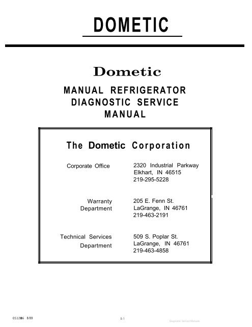
DOMETIC<br />
<strong>Dometic</strong><br />
MANUAL REFRIGERATOR<br />
DIAGNOSTIC SERVICE<br />
MANUAL<br />
The <strong>Dometic</strong> Corporation<br />
Corporate Office<br />
Warranty<br />
Department<br />
Technical <strong>Service</strong>s<br />
Department<br />
OS1286 8/89 D-l<br />
2320 Industrial Parkway<br />
Elkhart, IN 46515<br />
219-295-5228<br />
205 E. Fenn St.<br />
LaGrange, IN 46761<br />
219-463-2191<br />
509 S. Poplar St.<br />
LaGrange, IN 46761<br />
219-463-4858
NOTES:<br />
D-2
MANUAL REFRIGERATOR<br />
DIAGNOSTIC SERVICE ‘MANUAL<br />
<strong>Diagnostic</strong> Flow Charts<br />
Table of Contents<br />
No Operation . . . . . . . . . . . . .<br />
No 12OV AC Operation . . . . . . . . .<br />
No Gas Operation (Piezo Igniter) . . . .<br />
No Gas Operation (Automatic Reigniter) . .<br />
Operation and Diagnosis<br />
<strong>Dometic</strong> <strong>Manual</strong> <strong>Refrigerator</strong>s. . . . . . .<br />
Glossary of Terms . . . . . . . . . . . .<br />
<strong>Service</strong> Bulletins . . . . . . . . . . . .<br />
D-3<br />
Page<br />
D-4-l<br />
D-4-2<br />
D-4-3<br />
D-4-4<br />
D-6- 1<br />
D-8-l<br />
D-9-l
A.<br />
Check Supply Voltage<br />
1. 110 Volt Plug<br />
2. Wire Size<br />
B. V<br />
C.<br />
D.<br />
OK<br />
Check Fuse<br />
\/<br />
OK<br />
Check wiring<br />
1 OK<br />
Check Switch<br />
E. V<br />
OK<br />
Check Thermostat<br />
MANUAL REFRIGERATOR<br />
DIAGNOSTIC FLOW CHART<br />
1<br />
NO OPERATION<br />
I~>1Correct as Necessary<br />
NOT OK<br />
NOT OK<br />
NOT OK<br />
NOT OK<br />
D-4-l<br />
Correct as Necessary<br />
> Replace if Defective<br />
> Correct as Necessary<br />
> Correct as Necessary<br />
(Page D-6-20, Para. 66)<br />
, Correct as Necessary<br />
’ Continuity Check
A.<br />
1. Check AC Power<br />
2. <strong>Refrigerator</strong> Plugged in<br />
3. Breaker<br />
4. Coach Plug<br />
B. w<br />
OK<br />
Check Selector Switch<br />
c. V<br />
OK<br />
Check Thermostat<br />
I OK<br />
D. If<br />
Check 120 Volt Heater<br />
MANUAL REFRIGERATOR<br />
DIAGNOSTIC FLOW CHART<br />
NO 120 VOLT AC OPERATION<br />
~=I i Correct as Necessary<br />
NOT OK<br />
NOT OK<br />
NOT OK<br />
D-4-2<br />
Correct as Necessary<br />
(Page D-6-20, Para. 66)<br />
Correct as Necessary<br />
Continuity Check<br />
Correct as Necessary<br />
B Ohm’s Reading<br />
Bulletin #28<br />
(Page D-9-l 4, D-9-l 5)
.<br />
MANUAL REFRIGERATOR<br />
DIAGNOSTIC FLOW CHART<br />
NO GAS OPERATION - Models Equipped with Piezo igniter<br />
Check Gas Supply<br />
9OK<br />
B. v<br />
.C.<br />
Check Switch<br />
I<br />
OK<br />
Check Thermostat<br />
D. V<br />
F.<br />
OK<br />
Check Gas Pressure<br />
OK<br />
Check Flue & Burner<br />
I OK<br />
Check Piezo Resistance<br />
G. V<br />
I<br />
OK<br />
Check Piezo Electrode<br />
,H. V<br />
I<br />
OK<br />
Check Spark Gap<br />
of Electrode to Burner<br />
NOT OK<br />
NOT OK<br />
NOT OK<br />
NOT OK<br />
NOT OK<br />
NOT OK<br />
NOT OK<br />
D-4-3<br />
Correct as Necessary<br />
> (Page D-6-20, Para 66)<br />
Correct as Necessary<br />
=> Continuity Check<br />
><br />
Correct as Necessary<br />
(Page D-6-13, Para. 37)<br />
> Correct as Necessary<br />
No Obstructions<br />
Correct as Necessary<br />
> (Page D-6-l 8, Para. 58)<br />
r Replace Electrod<br />
Para<br />
> (Page D-6-18, Para. 58)<br />
><br />
Correct as Necessary<br />
(Page D-6-19, Para. 62)
A.<br />
MANUAL REFRIGERATOR<br />
DIAGNOSTIC FLOW CHART<br />
NO GAS OPERATION - Models Equipped with Automatic Reigniter<br />
Check Gas Pressure<br />
B. V<br />
I<br />
OK<br />
Check Gas Supply<br />
I OK<br />
C. v<br />
Check 12 Volt D.C.<br />
_E.<br />
Supply<br />
I OK<br />
Check Switch<br />
I OK<br />
Check Thermostat<br />
F. V<br />
OK<br />
NOT OK<br />
NOT OK<br />
NOT OK<br />
NOT OK<br />
NOT OK<br />
> Correct as Necessary<br />
(Page D-6-13, Para 37)<br />
Correct as Necessary<br />
> (Page D-6-14, Para. 40)<br />
> Correct as Necessary<br />
B<br />
Correct as Necessary<br />
(Page D-6-20, Para. 66)<br />
> Correct as Necessary<br />
Check for Continuity<br />
Clean Assembly &<br />
Check Flue & Burner > Orifice as Necessary<br />
NOT OK<br />
I OK<br />
,G. V<br />
Check Electrode ><br />
NOT OK<br />
Replace Electrode<br />
(Page D-6-19, Para. 62)
NOTES:<br />
D-5
OPERATION & DIAGNOSIS<br />
OF<br />
DOMETIC<br />
MANUAL REFRIGERATORS<br />
D-6-1
(1)<br />
This is <strong>Dometic</strong>’s <strong>Manual</strong> Refrigeration Diagnosis and Troubleshooting program. In this program<br />
we will discuss the way an absorption cooling unit operates, and the diagnostic procedures<br />
used to troubleshoot the complete refrigerator system.<br />
(2)<br />
Before we begin extensive troubleshooting<br />
procedures on the cooling unit, let’s take a few<br />
minutes to see how it operates.<br />
(3)<br />
The sealed combustion unit contains a<br />
mixture of ammonia, water and a rust<br />
inhibiting agent. After this solution is<br />
introduced into the coils, this unit is<br />
pressurized with hydrogen gas. When<br />
this system is in operation, the ammonia<br />
vaporizes in the hydrogen atmosphere<br />
and absorbs heat from inside<br />
the refrigerator.<br />
GAS<br />
TEMPERATURE<br />
EXCHANGER<br />
ABSORBER<br />
D-6-2<br />
VESSEL<br />
THE ABSORPTION SYSTEM<br />
Lil I<br />
EVAPORATOR<br />
BOILER<br />
.
(4)<br />
The cooling unit parts that accomplish this<br />
‘cooling’ or heat extraction process, include the:<br />
Boiler or Generator<br />
(5)<br />
Condenser<br />
(6)<br />
Evaporator<br />
D-6-3<br />
\ PUMP<br />
/ BOILER<br />
l------------- -l<br />
GAS<br />
TEMPERATUR<br />
EXCHANGER<br />
WATER<br />
SEPARATOR<br />
------------<br />
I<br />
I<br />
I<br />
I<br />
_-.I<br />
1<br />
I
(7)<br />
Absorber<br />
Because the self-contained cooling unit<br />
does not utilize an electric compressor<br />
or pump, the cooling coils can be operated<br />
from a variety of heat sources. LP<br />
gas, 120 volts AC and 12 volts DC<br />
heating elements are the most commonly<br />
used heat sources for recreational<br />
vehicle applications.<br />
(9)<br />
Before this cooling system can properly<br />
extract heat from the cabinet of the<br />
refrigerator, three requirements for proper<br />
refrigerator operation must be met.<br />
These are precise heat, specified ventilation<br />
and proper leveling.<br />
TEMPERATURE<br />
EXCHANGER<br />
D-6-4<br />
ABSORBER<br />
THE ABSORPTION SYSTEM<br />
TEMPERATURE<br />
EXCHANGER<br />
CONDENSER<br />
_<br />
EVAPORATOR<br />
THREE REQUIREMENTS<br />
FOR PROPER OPERATION<br />
1. Level<br />
2. Air Flow (Ventilation)<br />
3. Heat
(10)<br />
We will now take a closer look at how the<br />
cooling unit functions in normal operation.<br />
When proper heat is supplied to the boiler,<br />
ammonia vapor is produced and rises in the<br />
siphon pump, carrying with it a weak liquid<br />
ammonia solution. As seen from this drawing,<br />
the siphon pump, or pump tube, is an internal<br />
arrangement within the boiler section. The boiler<br />
section utilizes the ammonia-water liquid solution<br />
in the absorber and as it is heated, turns<br />
the solution into a strong ammonia vapor, which<br />
is needed to operate the system. This strong<br />
ammonia vapor rises from the pump tube to the<br />
condenser coil.<br />
Any deviation from the listed amount of<br />
heat to the absorption system will alter the<br />
ammonia to water ratio, which, in turn, will<br />
decrease the cooling unit’s overall efficiency.<br />
The weak ammonia solution which remains<br />
behind is diverted to the top of the absorber<br />
coils to perform a function that we will discuss<br />
in further detail later in the program.<br />
(11)<br />
The air that passes through the condenser fins,<br />
from the venting system, removes heat from the<br />
ammonia vapor, causing it to condense into a<br />
strong liquid ammonia solution. As a liquid, it<br />
then flows to the low temperature evaporator, or<br />
freezer companment, where it comes into<br />
contact with a hydrogen atmosphere. When this<br />
occurs, the ammonia begins to evaporate which<br />
draws heat from inside the freezer section, to<br />
the rear of the cooling unit.<br />
(12)<br />
This heat is then dissipated out through the<br />
upper vent, which allows the refrigerators<br />
interior temperature to properly maintain food<br />
storage requirements. Not all of the liquid<br />
ammonia evaporates in the freezer. What is left<br />
continues to evaporate as it flows to the high<br />
temperature evaporator, or food storage compartment.<br />
D-6-5<br />
c---_-------____---------__----_-__-7<br />
I I<br />
I WATER 1<br />
i<br />
I------------------------~<br />
ENSER<br />
PUMP<br />
/<br />
PI<br />
COLD INTERIOR
U 3)<br />
As this process continues, the ammonia and<br />
hydrogen vapors become intermixed and flow<br />
downward into the absorber vessel. As the<br />
ammonia vapor comes in close contact to the<br />
I<br />
1<br />
I<br />
I<br />
liquid ammonia solution in the absorber vessel, I<br />
the ammonia is absorbed into the liquid<br />
solution, allowing the hydrogen vapor to rise up<br />
through the absorber coils. After this absorption<br />
I<br />
I<br />
process, the vapor consists of mostly hydrogen<br />
with some traces of ammonia.<br />
I<br />
(14)<br />
To remove the remaining amounts of ammonia<br />
vapor still present in the hydrogen, a<br />
continuous flow of weak ammonia solution is<br />
fed, by gravity, to the top of the absorber coil<br />
from the boiler. As this weak ammonia solution<br />
flows downward through the absorber, it<br />
absorbs the ammonia vapor from the mixture,<br />
allowing the hydrogen vapor to rise through the<br />
absorber coil and return to the evaporator. With<br />
the hydrogen returned to the evaporator and<br />
the ammonia remixed into solution in the<br />
absorber vessel, the cooling process can<br />
continue.<br />
(15)<br />
Now that we have a basic understanding of<br />
proper cooling unit flow and operation, let’s<br />
take a step-by-step look at the three requirements<br />
for proper cooling unit operation. Please<br />
note it is essential that these three requirements<br />
be diagnosed before attempting to diagnose<br />
the cooling unit. A problem with leveling, heat<br />
input or ventilation may lead you to think that<br />
the cooling unit is faulty, when actually it is not.<br />
This causes an increased expense to you, the<br />
customer, and valuable shop time is wasted<br />
because of incorrect diagnosis, By following<br />
and checking the three unit requirements, costly<br />
diagnostic errors can be eliminated.<br />
D-6-6<br />
I--<br />
------- Ll_____i<br />
I<br />
---__------ I __A<br />
THREE REQUIREMENTS<br />
FOR PROPER OPERATION<br />
1. Level<br />
2. Air Flow (Ventilation)<br />
3. Heat
(16)<br />
Since the absorption system utilizes no<br />
mechanical pumps or compressors to circulate<br />
the refrigerant within the system, proper leveling<br />
is required to provide correct refrigerant flow in<br />
the gravity-feed system. Without proper leveling,<br />
refrigerant within the cooling coils will collect<br />
and stagnate at certain areas. When this<br />
happens the cooling process will stop.<br />
(17)<br />
On the older style cooling units equipped with<br />
square boiler box covers, this condition can<br />
cause permanent cooling unit failure. As we can<br />
see from this drawing, square boiler box<br />
cooling units utilize an exposed siphon pump<br />
tube which will become excessively superheated<br />
in an out-of-level condition. This can<br />
allow the rust inhibiting agent to chemically<br />
break down and permanently block or restrict<br />
the normal refrigerant flow through the pump.<br />
Shaking, tipping or so called ‘burping the<br />
refrigerator will not loosen or dislodge the<br />
blockage. The only recommended service<br />
procedure is to replace the cooling unit. To<br />
prevent this occurrence, proper leveling is of<br />
utmost importance when the RV is parked for<br />
any length of time.<br />
(18)<br />
To level these units, the spirit or bubble level<br />
should be placed in the approximate front and<br />
center of the floor of the freezer compartment.<br />
The coach should then be positioned so that at<br />
least 3/4 of the bubble is within the required<br />
mark while the refrigerator is in operation.<br />
REMEMBER: Failure to property level a square<br />
boiler box can result in a lack of cooling or<br />
permanent damage to the coding unit. When<br />
the vehicle is moving, leveling is not critical as<br />
the rolling and pitching movement of the RV will<br />
keep the solution in motion, preventing the<br />
solution from accumulating in the piping.<br />
D-6-7<br />
THREE REQUIREMENTS<br />
FOR PROPER OPERATION<br />
1. Level<br />
REFRIGERATOR IS TO BE LEVEL<br />
- -<br />
-<br />
m<br />
-_C==Z _ -5<br />
LEVELS
(19)<br />
In recent years <strong>Dometic</strong> has engineered a new<br />
type of cooling unit that utilizes an improved<br />
siphon pump tube design which drastically<br />
reduces the possibility of permanent damage to<br />
the coils if operated in an out-of-level condition,<br />
or too much heat is generated at the boiler<br />
section. As we can see from this drawing, the<br />
siphon pump tube is enclosed in the design<br />
and is surrounded by a weak ammonia solution,<br />
which will protect the pump tube from abnormally<br />
over-heating. This type of unit; however,<br />
does not eliminate the need for proper leveling.<br />
The unit still requires gravitational flow to<br />
provide the proper cooling process, and if<br />
leveling is outside the necessary limits, cooling<br />
will dramatically slow down or stop completely.<br />
The cooling coils are not normally damaged in<br />
this fashion and once proper leveling is maintained,<br />
the cooling process will resume.<br />
(20)<br />
Spirit or bubble levels are no longer being<br />
supplied with the new style refrigerators as the<br />
RV or vehicle only needs to be leveled so it is<br />
comfortable to live in, with no noticeable sloping<br />
of the floor or walls. For diagnosis, the new<br />
style cooling units that incorporate the<br />
protection boiler system, can be differentiated<br />
from the older style coils by the shape and<br />
design of the outer boiler box cover on the rear<br />
of the cooling unit. These units will incorporate<br />
a circular metal cover,<br />
. . . while the older style utilizes a square<br />
shaped enclosure. We will discuss diagnosis<br />
and troubleshooting of these units in more<br />
detail later in the program.<br />
\ PUMP<br />
I<br />
I<br />
I<br />
I<br />
I<br />
I<br />
I<br />
I<br />
I<br />
I<br />
I<br />
I<br />
I<br />
I<br />
I I
(22)<br />
The coach vent system must be able to provide<br />
a way to direct the hot air, produced by the<br />
action of the cooling unit, out away from the<br />
installation of the refrigerator.<br />
(23)<br />
In a good installation there should be as little<br />
open space as possible surrounding the sides<br />
and top of the refrigerator to achieve proper air<br />
flow. All potential dead air pockets should be<br />
blocked or baffled to insure that heat from the<br />
cooling unit won’t be trapped in these spaces<br />
and reduce efficiency. In addition, the cooling<br />
unit should be at least one inch from the<br />
nearest surface made of combustible materials.<br />
Please follow the installation manual for proper<br />
dimensions and clearances.<br />
RVIA requires that the refrigerator be<br />
installed in such a manner as to provide<br />
complete separation of the combustion system<br />
and the interior atmosphere of the recreational<br />
vehicle. This regulation requires all seams and<br />
joints in the enclosure be sealed. The undercounter<br />
installation is different. The addition of<br />
a metal chute the width of the enclosure, that<br />
extends from the upper side vent, will help<br />
eliminate the possibility of dead air pockets. It<br />
helps direct the hot air out the exhaust vent.<br />
The best method for venting the absorption<br />
refrigerator is with a lower side vent and a roof<br />
vent. Using proper <strong>Dometic</strong> vents will give you<br />
sufficient intake and exhaust areas for ventilation<br />
(24)<br />
Heat application to the boiler section of the<br />
cooling unit must be within the designed BTU’s.<br />
Never oversize the heating element on AC or<br />
DC power source. Always use the proper size<br />
orifice for gas modes. As explained earlier, any<br />
deviation will cause a potential cooling unit<br />
failure.<br />
D-6-9<br />
THREE REQUIREMENTS<br />
FOR PROPER OPERATION<br />
1. Level<br />
2. Air Flow (Ventilation)<br />
-------------<br />
I I<br />
1" FROM<br />
1<br />
0" CLEARANCE<br />
AIR FLOW _. .i<br />
,/‘,/, .,l I,,,, ,. n<br />
/ I<br />
I I<br />
I I<br />
-------------J<br />
THREE REQUIREMENTS<br />
FOR PROPER OPERATION<br />
1. Level<br />
2. Air Flow (Ventilation)<br />
3. Heat
(25)<br />
Three things must be remembered<br />
when diagnosing a cooling unit:<br />
First, circulation within the cooling<br />
unit is totally gravitational. This<br />
means proper leveling is important.<br />
Second, heat - created to boil<br />
the ammonia - now has to be dissipated<br />
into the surrounding air. Heat<br />
from the absorber and condenser must<br />
also be dissipated so as to cool the<br />
ammonia sufficiently.<br />
Third, proper heat application at<br />
the boiler section.<br />
(26)<br />
When diagnosing a cooling unit, remember this<br />
is the only part we cannot field check with test<br />
equipment, yet it is the simplest and quickest<br />
part to diagnose.<br />
(27)<br />
After the unit has been operating for<br />
approximately one hour, carefully touch the unit<br />
at the boiler box and the absorber area. These<br />
areas should be approximately the same<br />
temperature, regardless of the ambient<br />
temperature. Equal heat between the boiler and<br />
the absorber indicates the fluid circulation within<br />
the unit is good.<br />
TEMPERATURE<br />
EXCHANGER<br />
D-6-10<br />
THE ABSORPTION SYSTEM<br />
DIAGNOSING<br />
THE<br />
COOLING UNIT<br />
TEMPERATURE<br />
b<br />
GOOD CIRCULATION<br />
CONDENSER<br />
EVAPORATOF<br />
BOILER
(28)<br />
One of the faults with a cooling unit is<br />
a blockage. This can happen when the<br />
unit is operated off-ievel, or if too much<br />
heat has been applied to the boiler<br />
area. To the touch, this unit will be<br />
extremely hot at the boiler with little<br />
warmth at the absorber. In other words,<br />
no circulation.<br />
(29)<br />
This type of fault means a lost charge.<br />
It is known as a ‘leaker’. To the touch,<br />
this unit will be warm at the boiler and<br />
extremely hot at the absorber. In this<br />
condition we are still boiling ammonia<br />
but have no hydrogen for evaporation.<br />
(30)<br />
The following section of the program<br />
examines the <strong>Dometic</strong> manual refrigerator’s<br />
gas and electrical systems.<br />
<strong>Dometic</strong> refrigerators are designed for<br />
both piezo and automatic ignition. Both<br />
systems will be covered in this presentation.<br />
D-6-1 1<br />
T<br />
i_______________________________--________ G-- BOILER<br />
HOT GAS ONLY<br />
WARM<br />
BOILER<br />
.__i
(31)<br />
Let’s look at the current <strong>Dometic</strong> refrigerators<br />
and see how the gas flows.<br />
(32)<br />
Gas flows from the gas line to the shut-off valve<br />
and to the connection piece.<br />
(33)<br />
into the combination gas and electric thermostat<br />
(34)<br />
through the safety valve thermocouple<br />
test housing<br />
(35)<br />
D-6-12<br />
SHUT-OFF<br />
VALVE<br />
UNDERSTANDING<br />
THE<br />
GAS SYSTEM<br />
I GAS LINE =cYz=zc<br />
CONNECTION<br />
PIECE<br />
COMBINATION<br />
GAS & ELECTRIC W<br />
THERMOSTAT<br />
SAFETY VALVE/<br />
PRESSURE<br />
TEST v<br />
HOUSING ”
(36)<br />
and onto the orifice and burner assembly.<br />
Remember that except for the connection piece,<br />
all fittings are O-ring sealed. Whenever the<br />
system is separated the O-rings must be<br />
replaced.<br />
(37)<br />
To diagnose the gas system, connect a<br />
manometer to the test point. With the<br />
thermostat on maximum you must have 11<br />
inches water column pressure at this point. If<br />
you have 11 inches pressure, your problem<br />
Is to the right of the test point. If you do not<br />
have 11 inches water column pressure, the<br />
problem Is to the left.<br />
(38)<br />
Let’s take a closer look at the gas thermostat.<br />
In this drawing we will review how a thermostat<br />
functions. When the thermostat is working<br />
properly, the manometer will read line pressure<br />
when set at maximum and the refrigerator is<br />
trying to cool. From this drawing you can see<br />
the gas flow when the refrigerator is trying to<br />
cool. The gas flows through the thermostat at<br />
line pressure without restriction. The valve is<br />
open at this time. VALVE<br />
(39)<br />
The valve is now closed and the gas must flow<br />
through the by-pass screw; the gas is now<br />
diverted through the by-pass screw, which<br />
regulates the size of the low flame. This<br />
condition can only exist when the refrigerator is<br />
cold or the thermostat is set to minimum or off.<br />
If the sensing tube has lost its pressure, even<br />
with the thermostat set on maximum, you will<br />
have only low flame.<br />
D-6-13<br />
ORIFICE & BURNER<br />
ASSEMBLY<br />
_f===? DIAL SHAFT<br />
= DIAL SHAFT<br />
q._= /<br />
--c w- ,-<br />
i&‘-T -<br />
SCREW CLOSED VALVE
(40)<br />
The most efficient way to diagnose the gas<br />
system would be to first connect the gas<br />
manometer to the pressure test point. With the<br />
thermostat set at maximum you must have 11<br />
to 12 inches water column pressure for the<br />
refrigerator to operate properly. If your<br />
manometer reads higher than 11 to 12 inches<br />
water column pressure, the tank regulator is<br />
adjusted to high, readjust it. Make sure the<br />
gas system has at least 50% of the coach’s LP<br />
appliances on at the time the system is being<br />
adjusted. If the manometer reads 11 inches, the<br />
problem of no cooling lies in the burner<br />
assembly, flue pipe or venting.<br />
(41)<br />
If you have less than 11 inches water column<br />
pressure, the next step would be to remove the<br />
by-pass screw.<br />
NOTE: The by-pass screw<br />
reduces the pressure and<br />
volume of gas to the burner.<br />
(42)<br />
Shut off gas supply at the back of the refrigerator.<br />
Remove the by-pass screw from the top of<br />
the thermostat,<br />
Use a by-pass screw that does not have the<br />
small O-ring at the bottom. Reinstall this bypass<br />
screw into the thermostat.<br />
D-6-14
Turn on the main gas supply and take a<br />
reading. If the manometer now reads 11 inches,<br />
the thermostat is defective and must be<br />
replaced.<br />
(45)<br />
If the by-pass screw test shows no change in<br />
gas pressure, the problem lies with the gas<br />
supply to the refrigerator. Shut off the gas<br />
supply, remove the by-pass screw, replace it<br />
with one that has an O-ring and turn on gas<br />
supply. Remember to check for a gas leak. At<br />
this time we will take a look at the rest of the<br />
gas system.<br />
(46)<br />
The safety valve, or flame<br />
consists of a brass alloy<br />
failure safety device,<br />
valve housing and<br />
cap, an electro-magnet, and a thermocouple,<br />
which generates 14 to 30 millivolts when heat is<br />
applied to the tip. It is used to energize the<br />
electro-magnet in the safety valve. The purpose<br />
of this device is to insure that the flow of gas is<br />
shut off in the event flame is lost at the burner.<br />
If this should occur, the thermocouple cools,<br />
the magnet loses it magnetic field and the<br />
valve closes. Most failures of this device are<br />
related to the magnet, not the thermocouple.<br />
Should this happen, the complete safety valve<br />
should be replaced.<br />
D-6-15
(47)<br />
Once the gas has been allowed to pass<br />
through the safety valve, it flows to the gas jet<br />
and burner. These have been specifically<br />
designed to eliminate most of the normal maintenance<br />
required due to the corrosive contaminants<br />
in the gas, as well as soot and rust<br />
which fall from the flue pipe. The jet has an<br />
orifice made of an industrial ruby which has<br />
been laser-beam drilled. Each model of<br />
<strong>Dometic</strong> refrigerator uses a different size orifice<br />
in order to maintain the required amount of<br />
heat at the siphon pump. To clean the jet and<br />
burner, soak them in an alcohol base solvent<br />
and allow to air dry. DO NOT use a pin or<br />
needle. This will distort or shatter the orifice.<br />
(48)<br />
If you determine that disassembly is required,<br />
be aware there are two model designs for<br />
manual refrigerators. The design pictured here<br />
will be discussed first.<br />
(49)<br />
Shut off the main gas supply, then disconnect<br />
at the back of the refrigerator. Remove the<br />
cover over the thermostat and burner protection<br />
cover at the right,<br />
(50)<br />
Now disconnect the 12 volts at the terminal<br />
block and unplug the 120 volt cord. Remove<br />
the two mounting screws on the left and pull<br />
the metal locking arm out from under the<br />
burner housing.<br />
D-6-1 6
(51)<br />
The control assembly will now drop down and<br />
can be pulled outward for service.<br />
(52)<br />
Pictured here is the other model design. Make<br />
sure the main gas supply has been shut off<br />
and disconnect the gas supply line at the<br />
refrigerator.<br />
(53)<br />
Remove 3 screws on the burner cover plate.<br />
The sheet metal assembly should now slide out<br />
from the back of the refrigerator.<br />
Remove the 2 screws from the plastic cover.<br />
Also the 2 screws on the left and 2 screws on<br />
the right of the metal bracket.<br />
I
There are 3 screws in the burner area that<br />
must also be removed. Please note - these are<br />
machine screws, not sheet metal type. It is<br />
important for them to be reinstalled in this area<br />
only.<br />
(56)<br />
The control assernbly will now drop down and<br />
can be pulled out..,., Warfi ._, fnr crwvir~ 1-1 II”“.<br />
On the present line of manual refrigerators we<br />
use one of two methods of igniting the burner<br />
flame. Shown on the right is the piezo system;<br />
on the left is the igniter reigniter.<br />
(58)<br />
The piezo lighter is a self-contained assembly<br />
which generalty -does not need maintenance.<br />
When the button is ‘pushed, a spring loaded<br />
striker creates a spark. If there is no resistance<br />
when pressing the button, the piezo igniter is<br />
defective and must be replaced. If the piezo<br />
snaps or has resistance when the button is<br />
pushed, but there is no spark, the problem lies<br />
in the electrode or electrode wire.<br />
D-6-16
The igniter reigniter, used on certain <strong>Dometic</strong><br />
model refrigerators, operates on 12 volt current.<br />
On gas operation the igniter senses the resistance<br />
through the flame between the electrode<br />
and burner. When there is no flame at the<br />
burner, the resistance is high and the igniter<br />
begins sparking to light the burner. As soon as<br />
the flame is lit, the resistance between the<br />
electrode and burner drops and the igniter<br />
stops sparking. The resistance is monitored by<br />
the igniter, and, if for any reason the flame<br />
goes out, the igniter begins sparking until the<br />
burner is lit. This insures that the flame will<br />
always be lit when desired. Each time the<br />
igniter reigniter system sparks, a light will<br />
illuminate on the lower left front corner of the<br />
refrigerator.<br />
If the electrode does not spark first, make sure<br />
the igniter is receiving 12 volts. If the igniter is<br />
receiving 12 volts and produces no spark, it<br />
must be checked for operation.<br />
(61)<br />
Turn the refrigerator off and remove the wire<br />
between the electrode and igniter. Now turn the<br />
refrigerator to the gas mode. If no internal<br />
clicking sound is heard the igniter is defective.<br />
It is important to remove the high voltage wire<br />
that goes to the electrode from the igniter when<br />
you are checking the igniter for operation. The<br />
high voltage wire and the electrode can be<br />
shorted to ground causing the igniter reigniter<br />
to think that the flame is lit, resulting in no<br />
spark on gas operation.<br />
(62)<br />
The distance between the tip of the electrode<br />
and the burner, known as the spark gap,<br />
should be 3/16 of an inch. A greater distance<br />
will create a slow spark causing the light to<br />
blink. A lesser distance will create a fast spark<br />
that may not light the burner.<br />
D-6-19<br />
Burner<br />
SPARK GAP
w<br />
The Electrical System<br />
The electrical system consists of a combination<br />
switch assembly, heating element and<br />
thermostat. The quickest method of diagnosing<br />
the electrical system would be testing for<br />
continuity of components.<br />
Following the wiring diagram, the component<br />
that does not show continuity would be<br />
suspect.<br />
The selector switch should be checked for<br />
continuity in the following manner. Remove all<br />
wires from the assembly. Continuity should<br />
exist between terminals 1 and 1 A and 2 and 2A<br />
for the DC mode. When the switch is put in<br />
the gas mode, you should have continuity<br />
between 3 and 3A if the unit has an igniter<br />
reigniter.<br />
For the AC mode you should have<br />
continuity between 4L and 4A and 5N and 5A.<br />
If you find lack of continuity in any mode when<br />
making these checks, the switch is defective<br />
and should be replaced.<br />
D-6-20<br />
THE<br />
ELECTRICAL<br />
SYSTEM<br />
SWITCH ASSEMBLY<br />
DC Mode<br />
Gas<br />
Mode A/C Mode<br />
DC Mode Gas A/C Mode<br />
Mode
(67)<br />
Before an appliance can be sold to a recreational<br />
vehicle manufacturer it must be tested<br />
and approved by a nationally recognized<br />
testing laboratory for the specific end use<br />
intended. All <strong>Dometic</strong> refrigerators used in<br />
recreational vehicles have received this certification.<br />
If you require additional service assistance on<br />
the basic requirements for the cooling unit<br />
operation or the manual refrigeration, please<br />
refer to the diagnostic manual. For additional<br />
technical service assistance, contact the<br />
Technical <strong>Service</strong> Department at (219) 463-<br />
4858.<br />
(69)<br />
You are an essential part of a team that contributes<br />
greatly to the successful future of the<br />
RV industry, your dealership and <strong>Dometic</strong>.<br />
Thank you for participating in the training<br />
program.<br />
D-6-21<br />
I<strong>Dometic</strong>I
NOTES:<br />
D-7
Glossary of Terms<br />
MANUAL REFRIGERATION<br />
1. ABSORBER: Section of the cooling unit where the hydrogen and ammonia vapor are intermixed<br />
in the absorber. Ammonia vapor returns to solution and the hydrogen returns to the<br />
evaporator.<br />
2. BOILER: Section of the cooling unit where heat is applied. This is where the ammonia is<br />
partially separated from the water.<br />
3. BY-PASS SCREW: Small brass screw located on any <strong>Dometic</strong> gas thermostat that regulates gas<br />
flow in the low flame mode. There are three common sizes of this screw: S-17-350 BTU, S-<br />
14-325 BTU, S-l l-300 BTU.<br />
4. F o u n d GAS/ELECTRIC o n c uTHERMOSTAT: r r e n t <strong>Dometic</strong> m a n u a l<br />
refrigerators, this device is held in place with "0"" ring seals in the gas line and replaces<br />
separate electric and LP gas thermostat controls. On the LP gas mode, full line pressure is<br />
directed through the thermostat to the burner until the thermostat senses that the<br />
refrigerator cabinet has reached proper cooling temperature. At that rime an internal valve<br />
closes and redirects the gas flow through the by-pass screw. This reduces the amount of LP<br />
gas going to the burner assembly. The gas flow remains in this “by-pass” mode until the<br />
thermostat senses that the refrigerator cabinet needs more cooling. Again, the thermostat<br />
directs the LP gas flow through the thermostat at full line pressure until the cabinet<br />
temperature is sufficient. On the electric mode the internal mechanism breaks contact<br />
(continuity) when adequate cabinet temperature has been reached.<br />
5. CONDENSER: Section of the cooling unit that cools the ammonia vapor into ammonia liquid.<br />
6. COOLING UNIT: Self-contained, hermetically sealed set of steel coils where the refrigeration<br />
process takes place. The chemicals involved in the cooling process include hydrogen,<br />
ammonia, water and a rust inhibiting agent.<br />
7. CUT-OFF VALVE (Shut-Off Valve): Valve where the incoming propane supply is attached.<br />
This valve is direct-coupled to the selector switch by means of a steel clip. When the selector<br />
switch is turned to the electric mode, the cut-off valve is automatically closed. When this<br />
same switch is turned to the LP gas mode, the electric circuit is also automatically<br />
interrupted.<br />
8. EVAPORATION: A process that causes a liquid to turn into a vapor. Whenever evaporation<br />
takes place, heat is removed.<br />
9. EVAPORATOR: Section of the cooling unit where the cooling effect is produced. Liquid<br />
ammonia evaporating in a hydrogen atmosphere takes place in the evaporator.<br />
10. HEATING ELEMENTS: Elements that operate off either AC or DC voltage that create heat to<br />
the cooling unit.<br />
11. IGNITER-REIGNITER: The igniter-reigniter, used on certain <strong>Dometic</strong> model refrigerators,<br />
operates on 12 volt current. On gas operation the igniter senses the resistance through the<br />
flame between the electrode and burner. When there is no flame at the burner, the resistance<br />
is high and the igniter begins sparking to light the burner. As soon as the flame is lit, the<br />
resistance between the electrode and burner drops and the igniter stops sparking. The<br />
resistance is monitored by the igniter, and if for any reason the flame goes out, the igniter<br />
begins sparking until the burner is lit. This insures that the flame will always be lit when<br />
desired. Each time the igniter-reigniter system sparks, a light will illuminate on the lower<br />
left front corner of the refrigerator.<br />
12. L.P. GAS PRESSURE: For the refrigerator to operate properly on LP gas, the gas pressure<br />
should be set at 11” water column pressure. NOTE: use the test port at the rear of the<br />
refrigerator to take this reading.<br />
D-8-1
(Glossary of Terms . . continued)<br />
13.<br />
14.<br />
15.<br />
16.<br />
17.<br />
18.<br />
ORIFICE (JET): A small brass fitting that is mounted on the gas line just prior to the burner.<br />
This device incorporates a very small opening to greatly reduce gas flow to the burner. The<br />
orifice is cleaned by using an alcohol based solvent and allowing to air dry.<br />
PIEZO LIGHTER: Self-contained lighter assembly that is used to generate a spark to light the<br />
refrigerator on LP gas. This unit contains a quantity of quartz crystals that when pushed or<br />
snapped, produce a spark. There are no serviceable parts on this device.<br />
SAFETY DEVICE: An assembly of parts (safety valve, magnet and thermocouple) that shuts off<br />
the supply of LP gas to the burner assembly if the flame goes out for any reason. This is to<br />
ensure that a concentration of unburned gas does not accumulate in the refrigerator vent<br />
area.<br />
SELECTOR SWITCH: This is also a circuit interrupter on the 12 volt DC, 120 volt AC and gas<br />
sides of operation on the refrigerator. When the customer selects either DC, AC or GAS<br />
operation, the selector switch directs electricity first to the thermostat and on to the heating<br />
element, or igniter-reigniter. When this switch is turned off, the AC or DC circuit is<br />
interrupted.<br />
SPIRAL BAFFLE: Spiral metal device that is hung in the flue tube assembly of the cooling unit.<br />
The baffle causes the heat supplied by the gas burner to stay at the boiler assembly a longer<br />
period of time. This allows the absorption system to work as efficiently on LP gas as other<br />
heat sources.<br />
WATER COLUMN: The pressure rating given to LP gas line pressure. Usually this pressure can<br />
be varied by adjusting the regulator on the LP supply tank. A manometer is the device used<br />
to test LP gas pressure.<br />
D-8-2
TYPES OF BLOCKAGE<br />
To understand the absorption principle we have set up several refrigerators to inspect and diagnose.<br />
Carefully touch the absorber and boiler sections of each unit and record your findings. Proceed with<br />
caution as some of these units could be extremely HOT.<br />
Listed below are three types of units you will be testing:<br />
LI<br />
�<br />
LI<br />
GOOD COOLING UNIT<br />
Carefully touch the unit at the boiler box and the absorber area. These areas<br />
should be approximately the same temperature, regardless of the ambient<br />
temperature. The equal heat between the boiler and the absorber indicates the<br />
fluid circulation within the unit is good.<br />
BLOCKAGE<br />
One of the faults with a cooling unit is blockage. This can happen when the unit<br />
is operated off-level, or if too much heat has been applied to the boiler area. To<br />
the touch this unit will be extremely hot at the boiler with little warmth at the<br />
absorber. In other words, NO CIRCULATION.<br />
LEAKER<br />
This type of fault means the unit has lost its charge - it’s known as a “leaker”. To<br />
the touch this unit will be warm at the boiler and extremely hot at the absorber.<br />
In this condition we are still boiling ammonia but have no hydrogen for<br />
evaporation.<br />
D-9-l
CHANGING THE<br />
HINGE POSITION<br />
MODELS: 2600,2602,2800,2802, 3600,3601,3800 & 3801 I<br />
WHEN CHANGING THE HINGE POSITION:<br />
Insure that the door latch assembly operates<br />
properly after changing the hinge position from<br />
left to right, or vice-versa, with the following<br />
checks:<br />
A. The refrigerator door(s) opens and closes<br />
easily.<br />
B. The door gasket seals smoothly and completely<br />
on all sides.<br />
C. Slide the latch left to the locked position<br />
and try to open the door(s). The latch<br />
assembly should keep the door(s) from opening.<br />
NOTE: A hard pull will release the door<br />
latch assembly and the door(s) will<br />
open. This is not a fault. (If an<br />
adjustment is required, repeat the<br />
above procedure to determine the<br />
effectiveness of the repair.)<br />
SMOOTH FIT,<br />
PROPER SEAL SMOOTH FIT,<br />
PROPER SEAL<br />
FIG. 1<br />
D-9-2<br />
FIG. 2<br />
FlG. 3<br />
�]piGiGq<br />
<strong>Refrigerator</strong><br />
Bulletin R54/7A _<br />
March 1987<br />
R54/7A<br />
If the door(s) open when the latch assembly<br />
is in the locked position, adjust the hinge/door<br />
assembly. Follow the outlined steps to complete<br />
this procedure:<br />
1. Open the door and remove the two (2)<br />
front decoration screws located underneath<br />
the upper hinge assemblies.<br />
2. Remove the front decoration by lifting<br />
the decoration upward.<br />
3.<br />
4.<br />
Loosen the screws that hold the upper<br />
hinge in place.<br />
Reorient the door so the catch retainer<br />
on the door will engage with the latch<br />
assembly. (Usually lowering the door<br />
will accomplish this.)<br />
MOVABLE
(Bulletin R54/7A continued)<br />
5. Hold the door in its new position and<br />
carefully retighten the hinge screws,<br />
being careful not to change the hinge<br />
position.<br />
6. Close the door and again determine if<br />
the latch is now operational.<br />
7. If more adjustment of the door position<br />
is necessary, the center hinge screws<br />
may be loosened to reorient the door in<br />
the proper position.<br />
8. Again retighten the hinge screws to<br />
allow the latch to operate properly.<br />
SPECIAL HINTS TO ADJUST DOOR<br />
1. If there is a large distance between the lower door<br />
catch retainer and the latch, adjusting the hinge<br />
position still may not allow the latch to operate properly.<br />
FIG. 5<br />
EXCESSIVE<br />
GAP<br />
LATCH<br />
2. Remove the upper, and if necessary, the center hinge<br />
pin(s). This allows you to remove the refrigerator<br />
door(s).<br />
3. Place a metal, 1/4" flat washer (available at any<br />
hardware store) over the lower hinge pin and reinstall<br />
the door(s). This will raise the door to engage the<br />
latch assembly. (On very rare occasions two [2] washers<br />
may be required.)<br />
If the latch assembly still will not engage, the base can<br />
be repositioned to reorient the door as follows:<br />
1. Turn the refrigerator on its side to gain access to the<br />
four (4) base screws. Loosen all four (4) screws slightly.<br />
2. Reposition the base so that the door catch retainer<br />
engages with the latch.<br />
3. Retighten the base screws<br />
its new position.<br />
while holding the base in<br />
By following the above listed procedures you will be able<br />
to correct any door latching problems incurred when<br />
reversing the hinge position on your <strong>Dometic</strong> refrigerator.<br />
If you have any questions concerning<br />
contact our Technical <strong>Service</strong>s Department at:<br />
DOMETIC SALES CORPORATION<br />
509 South Poplar St.<br />
LaGrange, IN 46761<br />
this procedure,<br />
D-9-3<br />
FIG. 7<br />
BASE SCREWS
PROCEDURE FOR<br />
CHANGING COOLING UNIT<br />
The following categories have been established<br />
predicated on similarity of design and procedure<br />
for replacement of cooling units. Most <strong>Dometic</strong><br />
refrigerators are covered in one (1) of these<br />
categories.<br />
SPECIAL NOTE: After the cooling unit has been<br />
installed, the initial start-up time can be<br />
shortened by tilting the refrigerator from side<br />
to side and then from front to back before the<br />
refrigerator is turned on.<br />
TILT SIDE-TO-SIDE<br />
Run the refrigerator on a bench for 12 hours<br />
after the cooling unit has been installed (all<br />
food should be removed for testing).<br />
FC140 Cooling Unit cannot be replaced<br />
A. Category #l<br />
RM46 RM46 1 RM663 RM2500<br />
RM360 RM660 RM2300 RM3500<br />
RM460 RM661 RM2400<br />
REMOVAL OF COOLING UNIT<br />
1.<br />
2.<br />
3.<br />
4.<br />
5.<br />
6.<br />
Remove heater(s) from boiler case (FIG. Al).<br />
Disconnect burner from chimney (FIG. A2).<br />
Remove evaporator screws inside refrigerator<br />
and remove cooling flange (FIG. A3).<br />
Remove screws holding clamp for capillary<br />
tube. Pull capillary gently out of plug (FIG.<br />
A3).<br />
Remove screws holding unit from rear (FIG.<br />
Al).<br />
Apply leverage as shown and pull out (FIG.<br />
Al).<br />
D-9-4<br />
6<br />
\,<br />
FIG. Al<br />
FIG. A2<br />
FIG. A3<br />
\I<br />
<strong>Refrigerator</strong><br />
Bulletin R55/7A<br />
April 1987<br />
2<br />
WOOD BLOCK<br />
DPnTCPtth
(Bulletin R55/7A continued)<br />
INSTALL REPLACEMENT COOLING UNIT:<br />
1.<br />
2.<br />
3.<br />
4.<br />
5.<br />
6.<br />
7.<br />
Trim the Styrofoam portion of the cooling<br />
unit if it does not go freely into the<br />
refrigerator.<br />
Apply sealing permagum (sealing tape) on<br />
mounting plate (A; FIG. A4).<br />
Apply thermal mastic on the evaporator coil<br />
(B; FIG. A4).<br />
Tighten screws securely to obtain proper<br />
contact between the evaporator coil and<br />
evaporator flange; otherwise improper cabinet<br />
performance may result.<br />
Install the heating element completely back<br />
into the pocket and plug in.<br />
Reconnect burner assembly to chimney.<br />
Reinstall capillary tube into proper position<br />
(FIG. A3).<br />
B. Category #2<br />
FIG. A4<br />
RM100 RM763 RM1303<br />
RM760 RM1300 RM2600 RM3600<br />
RM76 1 RM1301 RM2800 RM3800<br />
REMOVAL OF COOLING UNIT:<br />
1.<br />
2.<br />
3.<br />
Remove screw holding clamp for capillary<br />
tube. Pull capillary tube out gently and<br />
place aside (FIG. Bl).<br />
a. RM3600, RM3800 (FIG. B4)<br />
Remove heater(s) from boiler case (FIG. Bl).<br />
Disconnect burner from chimney (FIG. B2<br />
and B3).<br />
a. RM2600, RM2800, RM3600, RM3800<br />
(FIG. B3).<br />
D-9-5<br />
4. Remove evaporator screws (FIG. B4).<br />
5. Remove screws holding unit from rear (FIG.<br />
Bl).<br />
6. Cut tape holding plate (FIG. B1).<br />
7. Apply leverage as shown and pull unit out<br />
(FIG. B ).<br />
5<br />
6<br />
G<br />
WOOD BLOCK<br />
-PROTECTION<br />
FIG. 84<br />
FIG. B3<br />
INSTALL REPLACEMENT COOLING UNIT:<br />
1. Trim the Styrofoam portion of the cooling<br />
unit if it does not go freely into the<br />
refrigerator.
(Bulletin R55/7A) continued)<br />
2.<br />
3.<br />
4.<br />
5.<br />
6.<br />
7.<br />
Apply sealing permagum (sealing tape) on<br />
mounting plate (A; FIG. B5).<br />
Apply thermal mastic on the evaporator coil<br />
(B; FIG. B5).<br />
Tighten screws securely to obtain proper<br />
contact between the evaporator coil and<br />
evaporator flange; otherwise improper cabinet<br />
performance may result.<br />
Install the heater element completely back<br />
into pocket and plug in.<br />
Reinstall capillary tube into proper position.<br />
a. RMl00, RM2600 & RM2800 will clamp to<br />
cooling flange. (FIG. B4)<br />
b. RM760, RM761 & RM763 will extend into<br />
retainer tube approximately 31” (FIG. Bl)<br />
C. RM1300, RM1301 ` RM1303 will extend<br />
into retainer tube approximately 36”<br />
(FIG. Bl)<br />
d. RM3600 & RM3800 have internal thermostat<br />
with capillary tube clamped to cooling<br />
flange (FIG. B4)<br />
Reconnect the burner assembly to chimney.<br />
FIG. B5<br />
SEALING PERMAGUM<br />
C. Category #3<br />
RC150 RC160<br />
REMOVAL OF COOLING UNIT:<br />
1. Remove screw and disconnect burner from<br />
chimney (FIG. Cl).<br />
2. Disconnect heater wires from terminal block<br />
(FIG. Cl).<br />
a. Remove heaters from boiler case (FIG. Cl).<br />
D-9-6<br />
3.<br />
4.<br />
5.<br />
6.<br />
7.<br />
Remove screws holding unit from rear (FIG.<br />
Cl).<br />
Disconnect green grounding wire (FIG. Cl).<br />
Pull out on cooling flange to remove fr<br />
evaporator coil (FIG. Cl).<br />
Pull thermostat capillary tube out gently and<br />
move so that cooling unit will clear (FIG. Cl).<br />
Remove cooling unit by hinging out on right<br />
side (FIG. Cl).<br />
INSTALL REPLACEMENT COOLING UNIT:<br />
1. Trim the Styrofoam portion of the cooling<br />
unit if it does not go freely into the<br />
2.<br />
refrigerator.<br />
Apply sealing permagum (sealing tape) on<br />
window insulation (A; FIG. C2).<br />
3. Apply thermal mastic on the evaporator coil<br />
(B; FIG. C2).<br />
4. Tighten screws securely to obtain proper<br />
seal; otherwise improper cabinet performance<br />
may result.<br />
5. Install the heat elements completely back<br />
into the pocket and attach to terminal block<br />
(FIG. Cl).<br />
6. Reconnect burner assembly to chimney (FIG.<br />
Cl).<br />
7. Reinstall capillary tube into proper position<br />
(FIG. Cl).<br />
SEALING PE<br />
(Sealing<br />
(A)<br />
FIG. C2
(Bulletin R55/7A continued)<br />
D. Category #4<br />
RM190 RM2190 RM2 192<br />
REMOVAL OF COOLING UNIT:<br />
1.<br />
2.<br />
3.<br />
4.<br />
5.<br />
FIG. D1<br />
Remove cover and flue tube, then disconnect<br />
burner from chimney (FIG. D1).<br />
Remove heater(s) from boiler case (FIG. Dl).<br />
Remove screws and take out evaporator fins<br />
and shelf (FIG. D2).<br />
Release holding clamp for thermostat capillary<br />
tube and pull tube out gently (FIG. D2).<br />
Remove one (1) screw and bend two (2) tabs<br />
and then pull cooling unit out (FIG. Dl).<br />
“\ 5<br />
INSTALL REPLACEMENT COOLING UNIT:<br />
1. Trim the Styrofoam portion of the cooling<br />
unit if it does not go freely into the<br />
refrigerator.<br />
2. Apply thermal mastic on the evaporator coil<br />
(B; FIG. D3).<br />
D-9-7<br />
3.<br />
4.<br />
5.<br />
6.<br />
7.<br />
Apply sealing permagum (sealing tape) on<br />
window insulation (A; FIG. D3).<br />
Tighten screws securely to obtain proper seal.<br />
Install the heating elements completely back<br />
into the pocket.<br />
Reinstall capillary tube into proper position.<br />
Reconnect burner assembly to chimney and<br />
replace cover.<br />
E. Category #5<br />
RM211<br />
FIG. D3<br />
A) SEALING<br />
PERMAGUM<br />
(Sealing Tape)<br />
REMOVAL OF COOLING UNIT:<br />
1. Remove cover and disconnect burner from<br />
chimney (FIG. El).<br />
2. Remove heater from boiler case (FIG. El).<br />
3. Remove three (3) screws holding unit from<br />
rear (FIG. E 1).<br />
4. Pull cooling unit part way out and then<br />
5.<br />
disconnect thermostat capillary tube and pull<br />
out (1; FIG. E2).<br />
Complete removal of cooling unit.<br />
6. Remove evaporator fins and shelf (2; FIG. E2).<br />
INSTALL REPLACEMENT COOLING UNIT:<br />
1.<br />
2.<br />
3.<br />
4.<br />
5.<br />
6.<br />
7.<br />
Apply thermal mastic on the evaporator coil<br />
(B; FIG. E2).<br />
Install evaporator fins and shelf (FIG. E2).<br />
Apply sealing permagum (sealing tape) on<br />
window insulation (A; FIG. E2).<br />
Reinstall capillary tube into proper position<br />
(FIG. E2).<br />
Tighten screws securely to obtain proper<br />
sealing.<br />
Reconnect burner assembly to chimney and<br />
replace cover (FIG. El).<br />
Install the heating elements completely back<br />
into the pocket (FIG. El).
3<br />
(Bulletin R55/7A continued)<br />
FIG. El<br />
FIG. E2<br />
F. Category #6 3<br />
RM75 RM76 RM77<br />
REMOVAL OF COOLING UNIT:<br />
1.<br />
2.<br />
3.<br />
3.<br />
5.<br />
Remove burner protection cover and remove<br />
burner from chimney (FIG. Fl).<br />
Remove heaters from boiler case (FIG. Fl).<br />
Remove evaporator screws (FIG. F2).<br />
Remove two (2) screws holding clamp for<br />
thermostat capillary tube. Pull capillary<br />
tube out gently (FIG. F2).<br />
Remove ten (10) screws holding unit from<br />
rear (FIG. Fl).<br />
6. Pull out on cooling unit and remove.<br />
5<br />
5<br />
FIG. F1<br />
-1<br />
2<br />
D-9-8<br />
INSTALL REPLACEMENT COOLING UNIT:<br />
1.<br />
3_.<br />
3.<br />
(A)<br />
SEALING<br />
PERMAGUM<br />
(Sealing Tape)<br />
Trim the Styrofoam portion of the cooling<br />
unit if it does not go freely into the<br />
refrigerator.<br />
Thermal mastic is not used on these units.<br />
Apply sealing permagum (sealing tape) on<br />
mounting plate (FIG. F3).
(Bulletin R55/7A continued<br />
4. Tighten screws securely to obtain proper seal.<br />
5. Install heating elements completely back into<br />
the pocket and plug in (FIG. Fl).<br />
6. Reconnect burner assembly to chimney (FIG.<br />
Fl ).<br />
7. Reinstall capillary tube into proper position<br />
(FIG. F2).<br />
FIG. F3<br />
G. Category #7<br />
REMOVAL OF COOLING UNIT:<br />
1.<br />
2.<br />
3.<br />
4.<br />
5.<br />
6.<br />
/ � THERMAL MASTIC IS NOT USED<br />
RM182<br />
Remove six (6) screws from burner cover<br />
(FIG. Gl).<br />
Disconnect burner from chimney (4 screws)<br />
(FIG. Gl).<br />
Remove heaters from boiler case (FIG. G1).<br />
Carefully pull out thermostat capillary tube<br />
(FIG. G1).<br />
Remove two (2) evaporator screws and take<br />
out ice tray support (FIG. G2).<br />
Remove eight (8) screws holding unit from<br />
rear (FIG. G1).<br />
Remove two (2) screws holding gas line<br />
gasket (FIG. Gl).<br />
INSTALL REPLACEMENT COOLING UNIT:<br />
1.<br />
2.<br />
3.<br />
4.<br />
Trim the Styrofoam portion of the cooling<br />
unit if it does not go freely into the<br />
refrigerator.<br />
Apply thermal mastic on the evaporator coil<br />
(B; FIG. G3).<br />
Apply sealing permagum (sealing tape) (A;<br />
FIG. G3).<br />
Reinstall thermostat capillary tube.<br />
D-9-9<br />
6<br />
5.<br />
6.<br />
7.<br />
Tighten screws securely to obtain proper seal.<br />
Install the heating elements completely back<br />
into the pocket.<br />
Reconnect burner assembly to chimney and<br />
replace cover.<br />
FIG. G1<br />
FIG. G2<br />
(A) SEALING PERMAGUM<br />
(Sealing Tape)<br />
FIG. G3
Before You Change<br />
That Cooling Unit<br />
PART I. PROPER DIAGNOSIS<br />
Cooling units are sometimes diagnosed as being<br />
defective when the actual problem is something<br />
else. Cooling units are expensive to replace, so<br />
it is important to make the correct diagnosis. By<br />
using the proper test procedures, you can eliminate<br />
all other possibilities before condemning the<br />
cooling unit.<br />
Any time the cooling unit is a possible suspect,<br />
use the following step-by-step procedure before<br />
replacing it.<br />
A.<br />
1.<br />
2.<br />
3.<br />
4.<br />
PRELIMINARY CHECKS<br />
Check for an ammonia smell around the<br />
cooling unit and inside the refrigerator.<br />
This could indicate a possible refrigerant<br />
leak. Check for any deposits of yellow<br />
powder on the tubing which will sometimes<br />
form around the area of a leak. NOTE: A<br />
yellow deposit in the area of the fill valve<br />
could be due to splashing of refrigerant<br />
during manufacture, and would not indicate<br />
a leak.<br />
Determine if the refrigerator works on one<br />
heat source but not another by testing it in<br />
the alternate modes. Also, ask the customer<br />
if he gets better cooling results from one<br />
energy source than another. If this is true,<br />
it indicates the problem is NOT in the cooling<br />
unit.<br />
Make sure the refrigerator is level. Sometimes<br />
the vehicle is level but the refrigerator is<br />
not, due to improper installation. Place a<br />
level on the bottom of the freezer compartment<br />
and check side-to-side and front-to-back<br />
levels (see FIG. Al). Use a mirror, if<br />
necessary to read the level.<br />
Carefully check door gaskets for proper<br />
seal. A leaking gasket can allow enough<br />
warm air inside the refrigerator to overcome<br />
most of the cooling being produced.<br />
D-9-l 0<br />
REFRlGERATOR<br />
BULLETIN R61/7A<br />
DEC. 1987<br />
For a simple method to check gaskets, close<br />
the door on a dollar bill, then pull the dollar<br />
bill out. If no resistance is felt, the gasket<br />
is not sealing properly. This should be done<br />
on all four sides of the door.<br />
FIG. Al<br />
\<br />
CHECK LEVEL<br />
BOTH WAY.<br />
5. Check the venting system to insure that<br />
ample air flow is provided at the back of<br />
the refrigerator.<br />
A. Check for, and remove, any restrictions<br />
in the vents, such as filters installed by<br />
the customer, bird nests in the roof<br />
vent, or smashed louvers in the wall<br />
vents (see FIG. A2).<br />
B. Make sure the correct roof vent has<br />
been installed. Larger models such as<br />
RM100, 760, 761, 1300, 1303, 2600, 2800,<br />
2802, 3600, 3800, 3802 and 4801, require<br />
a 5” X 24” opening for the roof vent<br />
Smaller models will also use the 5” J<br />
24” roof opening. To check this, measure<br />
the actual opening in the roof - DO<br />
NOT measure the roof vent itself. See<br />
FIG. A2.
(Bulletin c o n t i n u e d )<br />
FIG. A2<br />
Also, make sure the distance from<br />
the bottom of the refrigerator to the<br />
roof vent is at least the minimum<br />
dimension given in the Installation<br />
Instructions for each model. See FIG.<br />
A2.<br />
FOR MINIMUM<br />
DIMENSION.<br />
SEE INSTALLATION<br />
INSTRUCTIONS<br />
C.<br />
FIG. A3<br />
MIN. 5<br />
MAXIMUM OPEN<br />
SPACE 1 1/2 IN.<br />
(See 5D)<br />
CHECK FOR RESTRICTIONS<br />
IN AIR DUCTS OR VENTS<br />
(See 5A)<br />
Some smaller models may be installed<br />
with two side wall vents instead of<br />
using a roof vent. For this type of<br />
installation make sure the top of the<br />
upper vent is the correct distance above<br />
the refrigerator. See FIG. A3. The<br />
minimum dimension for this measurement<br />
is listed in the Installation Instructions<br />
for each model.<br />
CHECK MINIMUM<br />
HEIGHT (See<br />
Installation<br />
Instructions)<br />
L<br />
D-9-1 1<br />
D. Check the open space above the refrigerator.<br />
If this space is 1 1/2 inches or<br />
more it must be blocked off to prevent<br />
hot air from being trapped above the<br />
refrigerator. See FIG. A2.<br />
If venting is suspected as a problem, run the<br />
performance test described below with the refrigerator<br />
installed, then run the same test with<br />
the refrigerator removed. If there is a definite<br />
improvement in performance, a venting problem<br />
is indicated. Also, see Section B. PERFORMANCE<br />
TEST, Item 9.<br />
SPECIAL VENTING FOR DIRECT-VENT MODELS<br />
RM182, 215, 2192<br />
These models are designed to be installed in<br />
small vans and are usually placed in a cabinet<br />
that is not open to the outside of the vehicle.<br />
This means that air from within the vehicle<br />
must be used to cool the condenser.<br />
Customers with this type of installation must be<br />
made aware that the vehicle interior must be<br />
kept from getting too hot. If the vehicle is<br />
left parked in the sun, with all doors and windows<br />
closed, the inside temperature can quickly exceed<br />
100 degrees, and the cooling process will slow<br />
down or stop completely.<br />
REAR VIEW OF REFRIGERATOR<br />
Arrows indicate direction<br />
Alternative positions<br />
SIDE VIEW OF REFFERATOR +,,fi upper ventilator<br />
Arrows indicate direction<br />
of air flow over Cooling Unit<br />
Lower<br />
Ventilator
[Bulletin R61/7A continued)<br />
B.<br />
1.<br />
3<br />
3.<br />
4.<br />
PERFORMANCE TEST<br />
First perform all the preliminary checks<br />
described previously.<br />
Remove all food from the refrigerator and<br />
place all controls in the OFF position.<br />
Place an accurate thermometer in an ice<br />
cube tray, half filled with water, and place<br />
the tray in the center of the lower food<br />
storage compartment. NOTE: If a remotereading<br />
thermometer is used (allowing<br />
temperature readings without opening the<br />
door) the tray of water is not required.<br />
Make sure the AC heating element is the<br />
correct wattage for the model being tested,<br />
and that the resistance reading is correct.<br />
(See “Checking Resistance of a Heating<br />
Element” below.)<br />
Connect 120 volt AC power directly to<br />
the heating element leads (make sure the<br />
leads are not connected to the refrigerator<br />
circuit), then check the voltage at the<br />
element with a volt meter. Reading must<br />
show at least 115 volts.<br />
CHECKING RESISTANCE OF A HEATING ELEMENT<br />
A simple test to check a heating element is to<br />
measure the resistance through the element<br />
with an ohmmeter. The correct resistance, in<br />
ohms, can be calculated if the wattage and<br />
voltage ratings are known. (These ratings are<br />
stamped on all <strong>Dometic</strong> heating elements.)<br />
Use this Formula:<br />
Volts + (Watts + Volts) = Ohms<br />
Example:<br />
Heating element rated 135 Watts at 110 Volts.<br />
110 f (13.5 f 110) or,<br />
110 + 1.23 = 89.4 ohms<br />
The ohm reading should be within 10% of this<br />
figure, or between 80.46 and 98.34 ohms. Use<br />
the lowest setting on the ohmmeter which will<br />
give an accurate reading.<br />
When testing a 12 volt heating element, a<br />
very accurate ohmmeter must be used because<br />
of the very low readings that will be found.<br />
For example, a 200 watt element will have a<br />
reading of .72 ohms (less than 1 ohm).<br />
D-9-12<br />
5. After two hours of operation, check<br />
temperature on the back of the cooling<br />
with your hand, at the locations shown.<br />
FIG. Bl<br />
(TEMPERATURE<br />
TEST AREA)<br />
CONDENSER<br />
i3OBR<br />
ENCLOSURE<br />
the<br />
unit<br />
(TEMPERATURE<br />
TEST AREA)<br />
Under normal operation the temperature at<br />
the absorber coils (A) and the boiler (B)<br />
should be approximately the same. If the<br />
temperature at the absorber coils (A) is<br />
much hotter it indicates loss of refrigerant<br />
and the cooling unit must be replaced. If<br />
the temperature at the boiler (B) is very hot<br />
and the absorber coils (A) are cool it indicates<br />
that the refrigerant is not circulating properly.<br />
This could indicate:<br />
A. Liquid trapped in the evaporator sections,<br />
caused by out-of-level operation for a<br />
period of time. Resetting the refrigerator<br />
to a level position will not necessarily<br />
correct the problem as liquid can remain<br />
trapped even after level is corrected.<br />
Shut off the heat source and let the<br />
system cool down, then re-start it and<br />
observe the temperatures at A and B<br />
again after several hours. If the same<br />
condition exists it could indicate:<br />
B. A permanent blockage within the boiler<br />
pump tube, caused by too much heat<br />
applied to the burner (oversized orifice<br />
or heating element) or prolonged operation<br />
of the unit when out-of-level or with<br />
restricted ventilation. This type of<br />
blockage consists of hard deposits inside<br />
the boiler pump tube. This condition is<br />
not repairable and the cooling unit must<br />
be replaced.
(Bulletin R61/7A continued)<br />
NOTE: The cooling units currently being used<br />
are specially designed to prevent overheating of<br />
the boiler tube even when operated out-of-level.<br />
This special design can be identified by the<br />
round insulation box around the boiler, rather<br />
than the square-cornered box used on older units.<br />
Q<br />
FIG. B2<br />
3<br />
Older Style Current Style<br />
Boiler Enclosure Boiler Enclosure<br />
Blockage symptoms on the newer cooling units<br />
almost always, indicate trapped liquid in the<br />
evaporator, which can be corrected by proper<br />
leveling and allowing the cooling unit to cool<br />
off before restarting.<br />
6. If the temperatures are satisfactory in Step<br />
5, continue operating the unit, with power<br />
directly to the heating element, for a total<br />
of 10-12 hours. The doors must be kept<br />
closed for this entire period.<br />
7. If the temperature is within the previously<br />
mentioned guidelines the problem is not in<br />
the cooling unit. See Section II. OTHER<br />
CAUSES for additional items that could be<br />
causing a loss of cooling.<br />
8. If the temperature in the food compartment<br />
is higher than the acceptable limit, the<br />
cooling unit is probably defective. If you<br />
are still in question as to the performance<br />
of the cooling unit, please contact our Technical<br />
<strong>Service</strong> Department (219) 463-4858. See<br />
the next paragraph before changing the<br />
cooling unit.<br />
9. The importance of adequate air flow across<br />
the cooling unit cannot be emphasized too<br />
much. A minor restriction in the venting<br />
system will not create a problem on cooler<br />
days - the available air flow will still provide<br />
adequate cooling due to the lower temperature.<br />
However, on a hot day (90” or more) even<br />
a minor restriction will cause overheating of<br />
the cooling unit and the cooling process will<br />
slow down or stop.<br />
D-9-13<br />
= ONE LASTCHECK =<br />
If the previously mentioned test was performed<br />
in air temperatures above 90”. and the<br />
temperature in the refrigerator is above the<br />
acceptable ranges, it may indicate a restricted<br />
air flow. To make sure there is no problem<br />
with the venting system repeat the performance<br />
test with the refrigerator removed<br />
from its installed location and placed on<br />
the floor, or in your service shop. If the<br />
second test indicates satisfactory performance,<br />
re-check the venting and installation.<br />
PART II. OTHER CAUSES FOR<br />
LOSS OF COOLING<br />
If the previously mentioned performance test<br />
shows that the refrigerator is working satisfactorily,<br />
and the customer still experiences loss of<br />
cooling, the following items need to be considered:<br />
1. Make sure the customer is using the refrigerator<br />
properly. The cooling capacity of the<br />
absorption refrigerator is usually much lower<br />
than the refrigerator the customer has in his<br />
home, so the customer should be advised to<br />
follow the instructions for proper use in his<br />
Owner’s <strong>Manual</strong>.<br />
A. Start the refrigerator the day before it<br />
is to be filled with food.<br />
B. When the refrigerator is being filled<br />
when preparing for a trip, the food<br />
should be pre-cooled, and frozen foods<br />
should be pre-frozen, before placing<br />
them in the refrigerator. Ice making<br />
should be avoided until the refrigerator<br />
has cooled the lower compartment to the<br />
desired temperature.<br />
C. Air circulation within the food compartment<br />
is important for proper cooling.<br />
DO NOT place paper on the shelves or<br />
over-fill the compartment with large<br />
cartons, etc.<br />
D. Do not put hot food in the refrigerator.<br />
Allow it to cool in room air first.
REFRIGERATOR TECHNICAL DATA<br />
RAK1 00<br />
RAK1302<br />
� RC15<br />
RC65G<br />
RC65K<br />
� RC150<br />
� RC150A<br />
RC1 50TEG<br />
RC 150TEG<br />
� RC152<br />
RC160E<br />
RC 160E<br />
RC1 60TEG<br />
RC 1 60TEG<br />
� M52<br />
� M70<br />
9286111001 Kerosene<br />
9286179008 Kerosene<br />
2922000000 - - - - - - - -<br />
N/A 50 (0061667002)<br />
N/A Kerosene<br />
2922302001 - - - - - - - -<br />
2922471020 - - - - - - - -<br />
2942312022 (2928787031)<br />
2922441015 --------<br />
2942312022 (2928787031)<br />
2942312121 (2928787031)<br />
N/A<br />
________<br />
N/A ________<br />
� RM45,46,47 9283171008 51 (2002660179)<br />
� RM45,46,47<br />
RM46E 9283191006 43 (2002660161)<br />
RM46E<br />
� RM60,66 9283521004 52 (2002660187)<br />
� RM60,66<br />
RM66E 9283571009 52 (2002660187)<br />
RM66E<br />
RM66F 9283599000 51 (2002660179)<br />
RM66F<br />
* RM67 928352 1004 52 (2002660187)<br />
� RM67<br />
RM67D 9283521004 52 (2002660187)<br />
� RM67D 9283521004 52 (2002660187)<br />
� RM75,76,77,76DD 9285134004 53 (2002660195)<br />
�RM100 9286109005 58 (2002660211)<br />
� RM100<br />
RM182 2929302004 24 (2928787049)<br />
RM182B 2929302053 24 (2928787506)<br />
RM182B I I<br />
RM190 9281 152000 F (2902540059)<br />
� RM211 t 9282740010 1 4 (2901860010)<br />
� RM2llB 19282743005 1 4 (2901860010)<br />
RM215 19282761000 t J (2902540075)<br />
� Models that use brass heating elements approximately 3/4’ in diameter.<br />
D-9-14<br />
B]1DOmeticl
(Bulletin 828 . continued)<br />
RM3601 215/12 0173757022 17.9<br />
RM3604 2934803996 53 (2007419191) 295/120 0173754045 2.5 48 ___<br />
RM3604 215112 0173757022 17.9<br />
RM3800 2934901097 58 (2007419217) 325/120 0173742081 2.7 44 ___<br />
� Models that use brass heating elements approximately 3/4’ in diameter.<br />
D-9-15
(Bulletin #28 continued)<br />
� Models that use brass heating elements approximately 3/4’ in diameter.<br />
NOTE: The formula for calculating amps & OHMS:<br />
Watts + Volts (120/12) = AMPS<br />
Volts (120) + Amps = OHMS<br />
D-9-16
Replacement of cooling units in RM760.<br />
Cooling unit 531A will replace 530A in production and service.<br />
Ell[ <strong>Dometic</strong> 1<br />
BULLETIN # 4 5<br />
MAY 1983<br />
When installing 331A as replacement for 530A three new holes should be drilled in the cooling<br />
flange.<br />
New holes +<br />
1 3/16” (29 mm)<br />
down.<br />
0 J<br />
0 c<br />
0 0<br />
0 0<br />
0 0<br />
~ 0 0<br />
0<br />
0<br />
Furthermore the hole for the air channel (no longer necessary) in the burner box should be covered<br />
by a piece of aluminium tape (No combustible material must be used).<br />
Cover this hole<br />
D-9-17
Kl: <strong>Dometic</strong><br />
REFRIGERATOR BULLETIN<br />
REVISED AUGUST, 1984 #38<br />
CROSS REFERENCE OF REFRIGERATORS MANUFACTURED BY<br />
A.B. ELECTROLUX AND DOMETlCARE PROCEDURE CHANGES<br />
SUBJECT: <strong>Dometic</strong>are Procedure<br />
An out of warranty cooling unit purchased from <strong>Dometic</strong> for installation on<br />
an Instamatic, Magic Chef, Hadco or GE refrigerator does not qualify for our<br />
three year <strong>Dometic</strong>are cooling unit coverage.<br />
We will warrant cooling units purchased from <strong>Dometic</strong> for installation on<br />
other than <strong>Dometic</strong> refrigerators for two (2) years providing the installation is<br />
within our established installation specifications.<br />
We will offer our three year <strong>Dometic</strong>are coverage on the following cooling<br />
units purchased from <strong>Dometic</strong> for out of warranty <strong>Dometic</strong> refrigerators only,<br />
for $35.00.<br />
RC 150 RM 215 RM 361 RM 66 RM 663 RM 763 RAK 100<br />
RM 182 RM 235 RM 46 RM 66E RM 76 RM 100 RAK 1302<br />
RM 19a RM 36C RM 46E RM 66F RM 77 RM 13C0 RA 1300<br />
RM 211 RM 36E RM 460 RM 660 RM 760 RM 1303 RA 1302<br />
RM 2118 RM 360 RM 461 RM 661 RM 761 RA 100 RC 65<br />
All <strong>Dometic</strong> cooling units for <strong>Dometic</strong> refrigerators manufactured prior to<br />
these models will no longer qualify for our Dometjcare coverage. -<br />
CROSS REFERENCE OF REFRIGERATORS MANUFACTURED BY<br />
A.B. ELECTROLUX<br />
HADCO DOMETIC<br />
HR-2 same as RM 24<br />
HR-3 same as RM 36C<br />
HR.4 same as RM 460<br />
HR-6 same as RM 660<br />
HR-7 same as RM 760<br />
MAGIC CHEF<br />
MKM<br />
MKM-110<br />
MKM-150<br />
R-82, 83, 84,85,86<br />
R-87<br />
R-88<br />
DOM ETIC<br />
same as M-28<br />
same as M-40<br />
same as M-52<br />
same as RM 75<br />
same as RM 77<br />
same as RM 760<br />
D-9-1 8<br />
GE DOMETIC<br />
TG3z08 same as RM 36<br />
TG4-S-06 same as RM 65<br />
TGS-S-06 same as RM 60<br />
INSTAMATIC DOMETIC<br />
IM-2 same as RX1 211<br />
IM-3 same as Rhl 36E<br />
IM-4 same as Rhl 46E<br />
IM-6 same as 66E<br />
IM-7 same as R!d 77<br />
IM-10 same as RLI 100
HEATING ELEMENTS 360-460-660-760<br />
Previous literature covering the following models, lists the wattage of 110 volt<br />
heading elements as follows:<br />
RM360 -120 watts<br />
RM460 -135 watts<br />
RM660 -175 watts<br />
RM760 -250 watts<br />
The ratings that are actually stamped on the replacement heating elements are<br />
as follows:<br />
RM360 -135 watts<br />
RM460 -150 watts<br />
RM660 -190 watts<br />
RM760 -275 watts<br />
These elements are identical and are covered under the same part numbers.<br />
The difference being that the newer elements have been rated at 115 volt input<br />
rather than 110 volt input.<br />
The American Gas Association now requires that every refrigerator be<br />
supplied with a spare parts list included inside the cabinet. They are also<br />
requiring that all literature packaged inside the cabinet, from this point on, rate<br />
electrical input at 120 volt A.C. Therefore, the new spare parts list supplied with<br />
the refrigerator will list the wattage, at 120 volt input, as follows:<br />
RM360-150 watts<br />
RM460 - 160 watts<br />
RM660 - 210 watts<br />
RM760 - 295 watts<br />
Once again, these elements are identical to the previous elements and are<br />
covered under the same part numbers which are as follows:<br />
RM360 - 173734-01 I3<br />
RM460 - 173736-0118<br />
RM660-173738-0114<br />
RM760-173740-0110<br />
Should a customer be concerned that the wattage stamped on the heating<br />
element does not correspond to that shown in his spare parts list, the above<br />
information should be passed on to him.<br />
D-9-19
THE ABSORPTION SYSTEM<br />
A - \i’EAK A~I~IOSIA SOLUTION<br />
B - STROSG AXIhIOSIA SOLUTION<br />
c - LIQUID A~I>lO~IA<br />
D - X313lOSIA VAPOR<br />
E - HYDROGEN GAS<br />
F - HYDROGES 5; A~IllO~;IA VAPOR<br />
D-9-20<br />
WATER SEPARATOR<br />
VAPOR PIPE