ACME 2011 Proceedings of the 19 UK National Conference of the ...
ACME 2011 Proceedings of the 19 UK National Conference of the ...
ACME 2011 Proceedings of the 19 UK National Conference of the ...
Create successful ePaper yourself
Turn your PDF publications into a flip-book with our unique Google optimized e-Paper software.
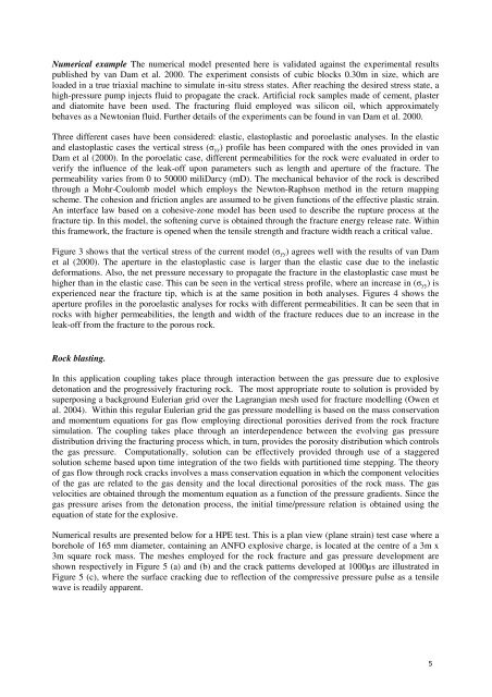
Numerical example The numerical model presented here is validated against <strong>the</strong> experimental results<br />
published by van Dam et al. 2000. The experiment consists <strong>of</strong> cubic blocks 0.30m in size, which are<br />
loaded in a true triaxial machine to simulate in-situ stress states. After reaching <strong>the</strong> desired stress state, a<br />
high-pressure pump injects fluid to propagate <strong>the</strong> crack. Artificial rock samples made <strong>of</strong> cement, plaster<br />
and diatomite have been used. The fracturing fluid employed was silicon oil, which approximately<br />
behaves as a Newtonian fluid. Fur<strong>the</strong>r details <strong>of</strong> <strong>the</strong> experiments can be found in van Dam et al. 2000.<br />
Three different cases have been considered: elastic, elastoplastic and poroelastic analyses. In <strong>the</strong> elastic<br />
and elastoplastic cases <strong>the</strong> vertical stress (σyy) pr<strong>of</strong>ile has been compared with <strong>the</strong> ones provided in van<br />
Dam et al (2000). In <strong>the</strong> poroelatic case, different permeabilities for <strong>the</strong> rock were evaluated in order to<br />
verify <strong>the</strong> influence <strong>of</strong> <strong>the</strong> leak-<strong>of</strong>f upon parameters such as length and aperture <strong>of</strong> <strong>the</strong> fracture. The<br />
permeability varies from 0 to 50000 miliDarcy (mD). The mechanical behavior <strong>of</strong> <strong>the</strong> rock is described<br />
through a Mohr-Coulomb model which employs <strong>the</strong> Newton-Raphson method in <strong>the</strong> return mapping<br />
scheme. The cohesion and friction angles are assumed to be given functions <strong>of</strong> <strong>the</strong> effective plastic strain.<br />
An interface law based on a cohesive-zone model has been used to describe <strong>the</strong> rupture process at <strong>the</strong><br />
fracture tip. In this model, <strong>the</strong> s<strong>of</strong>tening curve is obtained through <strong>the</strong> fracture energy release rate. Within<br />
this framework, <strong>the</strong> fracture is opened when <strong>the</strong> tensile strength and fracture width reach a critical value.<br />
Figure 3 shows that <strong>the</strong> vertical stress <strong>of</strong> <strong>the</strong> current model (σyy) agrees well with <strong>the</strong> results <strong>of</strong> van Dam<br />
et al (2000). The aperture in <strong>the</strong> elastoplastic case is larger than <strong>the</strong> elastic case due to <strong>the</strong> inelastic<br />
deformations. Also, <strong>the</strong> net pressure necessary to propagate <strong>the</strong> fracture in <strong>the</strong> elastoplastic case must be<br />
higher than in <strong>the</strong> elastic case. This can be seen in <strong>the</strong> vertical stress pr<strong>of</strong>ile, where an increase in (σyy) is<br />
experienced near <strong>the</strong> fracture tip, which is at <strong>the</strong> same position in both analyses. Figures 4 shows <strong>the</strong><br />
aperture pr<strong>of</strong>iles in <strong>the</strong> poroelastic analyses for rocks with different permeabilities. It can be seen that in<br />
rocks with higher permeabilities, <strong>the</strong> length and width <strong>of</strong> <strong>the</strong> fracture reduces due to an increase in <strong>the</strong><br />
leak-<strong>of</strong>f from <strong>the</strong> fracture to <strong>the</strong> porous rock.<br />
Rock blasting.<br />
In this application coupling takes place through interaction between <strong>the</strong> gas pressure due to explosive<br />
detonation and <strong>the</strong> progressively fracturing rock. The most appropriate route to solution is provided by<br />
superposing a background Eulerian grid over <strong>the</strong> Lagrangian mesh used for fracture modelling (Owen et<br />
al. 2004). Within this regular Eulerian grid <strong>the</strong> gas pressure modelling is based on <strong>the</strong> mass conservation<br />
and momentum equations for gas flow employing directional porosities derived from <strong>the</strong> rock fracture<br />
simulation. The coupling takes place through an interdependence between <strong>the</strong> evolving gas pressure<br />
distribution driving <strong>the</strong> fracturing process which, in turn, provides <strong>the</strong> porosity distribution which controls<br />
<strong>the</strong> gas pressure. Computationally, solution can be effectively provided through use <strong>of</strong> a staggered<br />
solution scheme based upon time integration <strong>of</strong> <strong>the</strong> two fields with partitioned time stepping. The <strong>the</strong>ory<br />
<strong>of</strong> gas flow through rock cracks involves a mass conservation equation in which <strong>the</strong> component velocities<br />
<strong>of</strong> <strong>the</strong> gas are related to <strong>the</strong> gas density and <strong>the</strong> local directional porosities <strong>of</strong> <strong>the</strong> rock mass. The gas<br />
velocities are obtained through <strong>the</strong> momentum equation as a function <strong>of</strong> <strong>the</strong> pressure gradients. Since <strong>the</strong><br />
gas pressure arises from <strong>the</strong> detonation process, <strong>the</strong> initial time/pressure relation is obtained using <strong>the</strong><br />
equation <strong>of</strong> state for <strong>the</strong> explosive.<br />
Numerical results are presented below for a HPE test. This is a plan view (plane strain) test case where a<br />
borehole <strong>of</strong> 165 mm diameter, containing an ANFO explosive charge, is located at <strong>the</strong> centre <strong>of</strong> a 3m x<br />
3m square rock mass. The meshes employed for <strong>the</strong> rock fracture and gas pressure development are<br />
shown respectively in Figure 5 (a) and (b) and <strong>the</strong> crack patterns developed at 1000µs are illustrated in<br />
Figure 5 (c), where <strong>the</strong> surface cracking due to reflection <strong>of</strong> <strong>the</strong> compressive pressure pulse as a tensile<br />
wave is readily apparent.<br />
5


