- Page 1: ACME 2011 Proceedings of the 19 th
- Page 4 and 5: First published 2011 by Heriot-Watt
- Page 7 and 8: CONTENTS Invited Lectures CHALLENGE
- Page 9 and 10: A DAMAGE-MECHANICS-BASED RATE-DEPEN
- Page 11: A PROJECTED QUASI-NEWTON METHOD FOR
- Page 14 and 15: minimise the strain energy density.
- Page 16 and 17: through individual rock blocks and
- Page 18 and 19: (a) Finite element mesh (b) Gas mes
- Page 21 and 22: Proceedings of the 19 th UK Confere
- Page 23 and 24: T E −1 ( ) ( ) T ∂s ∂T − du
- Page 25 and 26: Proceedings of the 19 th UK Confere
- Page 27 and 28: nondimensional tangential velocity
- Page 29 and 30: Proceedings of the 19 th UK Confere
- Page 31 and 32: Figure 2: Results for an open arter
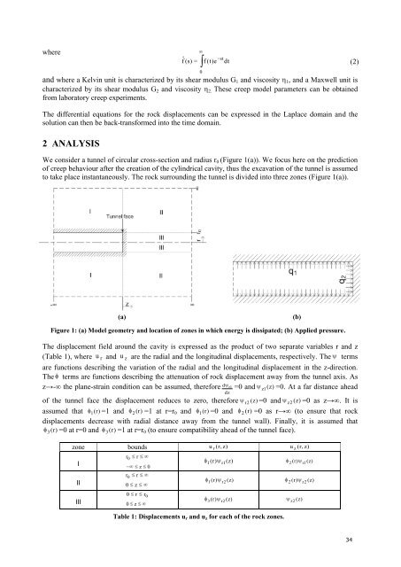
- Page 33 and 34: Proceedings of the 19 th UK Confere
- Page 35 and 36: (a) Abaqus model von Mises stress (
- Page 37 and 38: Proceedings of the 19 th UK Confere
- Page 39 and 40: Vle Vli De Di k1 (MPa) 8.34 2.11 1.
- Page 41 and 42: Proceedings of the 19 th UK Confere
- Page 43 and 44: 3 RESULTS AND DISCUSSIONS In this p
- Page 45: Proceedings of the 19 th UK Confere
- Page 49 and 50: Proceedings of the 19 th UK Confere
- Page 51 and 52: where the problem is formulated in
- Page 53 and 54: Proceedings of the 19 th UK Confere
- Page 55 and 56: Figure 1: 2D slope model geometry (
- Page 57 and 58: Proceedings of the 19 th UK Confere
- Page 59 and 60: Figure 1. Comparison between the pr
- Page 61 and 62: Proceedings of the 19 th UK Confere
- Page 63 and 64: following anisotropic hardening rel
- Page 65 and 66: Proceedings of the 19 th UK Confere
- Page 67 and 68: that R Γ Spin[N]XdΓ = 0, the func
- Page 69 and 70: Proceedings of the 19 th UK Confere
- Page 71 and 72: 4 INCORPORATING EPRCM IN FEA The de
- Page 73 and 74: Proceedings of the 19 th UK Confere
- Page 75 and 76: No distinct yield point is observed
- Page 77 and 78: Proceedings of the 19 th UK Confere
- Page 79 and 80: stress [MPa] 1 0 -1 -2 -3 -2.5 -2 -
- Page 81 and 82: Proceedings of the 19 th UK Confere
- Page 83 and 84: ecomes available, the material mode
- Page 85 and 86: Proceedings of the 19 th UK Confere
- Page 87 and 88: where ∂fin ∂UM force 2.5 2 1.5
- Page 89 and 90: Proceedings of the 19 th UK Confere
- Page 91 and 92: Practicallly, the perturbation fiel
- Page 93 and 94: Proceedings of the 19 th UK Confere
- Page 95 and 96: 3 SIMULATING CONCRETE MESO-STRUCTUR
- Page 97 and 98:
Proceedings of the 19 th UK Confere
- Page 99 and 100:
Proceedings of the 19 th UK Confere
- Page 101 and 102:
Proceedings of the 19 th UK Confere
- Page 103 and 104:
¯K i is an approximation of the co
- Page 105 and 106:
Proceedings of the 19 th UK Confere
- Page 107 and 108:
h = 5.36 matrix 4.3 z P E f νf 0.9
- Page 109 and 110:
Proceedings of the 19 th UK Confere
- Page 111 and 112:
From the total hoop strainε θ , t
- Page 113 and 114:
Proceedings of the 19 th UK Confere
- Page 115 and 116:
3 EXTERIOR POINT ESHELBY BASED CRAC
- Page 117 and 118:
Proceedings of the 19 th UK Confere
- Page 119 and 120:
is applied uniformly on the edge to
- Page 121 and 122:
Proceedings of the 19 th UK Confere
- Page 123 and 124:
(a) (b) (c) (d) Figure 1: Influence
- Page 125 and 126:
Proceedings of the 19 th UK Confere
- Page 127 and 128:
On each subdomain, we then have to
- Page 129 and 130:
Proceedings of the 19 th UK Confere
- Page 131 and 132:
( i�1) ( i�1) �Un�1 � ε
- Page 133 and 134:
Proceedings of the 19 th UK Confere
- Page 135 and 136:
� ~ � 1 ψ ~ � � ~ (2) �
- Page 137 and 138:
Proceedings of the 19 th UK Confere
- Page 139 and 140:
For the case of uni-axial tension,
- Page 141 and 142:
Proceedings of the 19 th UK Confere
- Page 143 and 144:
3 Numerical results Preliminary num
- Page 145 and 146:
Proceedings of the 19 th UK Confere
- Page 147 and 148:
The coefficients An cannot be deriv
- Page 149 and 150:
Proceedings of the 19 th UK Confere
- Page 151 and 152:
The spatial semi-discretisation is
- Page 153 and 154:
Proceedings of the 19 th UK Confere
- Page 155 and 156:
3 CRITICAL TIME STEP INCREASED WITH
- Page 157 and 158:
Proceedings of the 19 th UK Confere
- Page 159 and 160:
v/vo 2E-05 1.5E-05 1E-05 5E-06 0 -3
- Page 161 and 162:
Proceedings of the 19 th UK Confere
- Page 163 and 164:
3 RESULTS AND DISCUSSION Fig. 1a sh
- Page 165 and 166:
Proceedings of the 19 th UK Confere
- Page 167 and 168:
Model updating from eigenvalue and
- Page 169 and 170:
Proceedings of the 19 th UK Confere
- Page 171 and 172:
1. If R = ω 2 n, there is no eigen
- Page 173 and 174:
Proceedings of the 19 th UK Confere
- Page 175 and 176:
F = ´ Ω STv CSv dΩ A = ´ Γ U
- Page 177 and 178:
Proceedings of the 19 th UK Confere
- Page 179 and 180:
Fig. 3 Wall normal pressure in the
- Page 181 and 182:
Proceedings of the 19 th UK Confere
- Page 183 and 184:
contact contact (ii). f ≈ f ( d,
- Page 185 and 186:
Proceedings of the 19 th UK Confere
- Page 187 and 188:
In the analysis of the incident P-w
- Page 189 and 190:
Proceedings of the 19 th UK Confere
- Page 191 and 192:
elow a certain threshold. In both t
- Page 193 and 194:
Proceedings of the 19 th UK Confere
- Page 195 and 196:
K/d 2 Effective Permeability 0.0032
- Page 197 and 198:
Proceedings of the 19 th UK Confere
- Page 199 and 200:
METHOD 2 (Mellor and Herring Type)
- Page 201:
Proceedings of the 19 th UK Confere
- Page 204 and 205:
(a) Free Surface Profile from Janos
- Page 206 and 207:
2 IMMERSED FLUID SOLVER Consider th
- Page 208 and 209:
References [1] R. Mittal and G. Iac
- Page 210 and 211:
a second impact on the forward fuse
- Page 212 and 213:
Acknowledgement L. Papagiannis is f
- Page 214 and 215:
acceptable probability throughout t
- Page 216 and 217:
algorithm was then responsible for
- Page 218 and 219:
strategy of saving the computationa
- Page 220 and 221:
(a) (b) Figure 5. Comparison of (a)
- Page 222 and 223:
Thermal load step i i i i Update ,
- Page 224 and 225:
Displacement (mm) Conclusions 45 40
- Page 226 and 227:
load carrying of the structure to b
- Page 228 and 229:
compressive stress field between co
- Page 230 and 231:
Unbonded flexible pipes and risers
- Page 232 and 233:
Figure 2: (a) Riser configuration (
- Page 234 and 235:
Furthermore the total strain varies
- Page 236 and 237:
Displacement 14 12 10 8 6 4 2 0 Mem
- Page 238 and 239:
As this project was in the conceptu
- Page 240 and 241:
kg and additional mass to represent
- Page 242 and 243:
1 Step make box 2 Step make cylinde
- Page 244 and 245:
element method. The solid model is
- Page 246 and 247:
just new element classes) without t
- Page 248 and 249:
Fig.4. Frame model and the displace
- Page 250 and 251:
capacities to meet with such demand
- Page 252 and 253:
esponses. Severe cases are to be co
- Page 254 and 255:
2 Numerical results In this section
- Page 256 and 257:
the frequency intially increases un
- Page 258 and 259:
and F (R) = ⎡ ⎢ ⎣ ... UαT (R
- Page 260 and 261:
Merit function g 10 1 10 0 10 -1 10
- Page 262 and 263:
2 STRUCTURAL CHARACTERISTICS OF PTM
- Page 264 and 265:
Fig. 5. Simplified FE model of a PT
- Page 266 and 267:
general the computational results o
- Page 268 and 269:
References [1] Ainsworth M, Oden JT
- Page 270 and 271:
Error Cause Interpolation Error Ele
- Page 272 and 273:
(a) Before Improvement (b) After Im
- Page 274 and 275:
een applied to FE fluid flow proble
- Page 276 and 277:
Acknowledgements Figure 2: Flowchar
- Page 278 and 279:
1 1 ′′ 1 ′′′ 3 ′′ 2
- Page 280 and 281:
3 COMBINING SHAPE FUNCTIONS The exp
- Page 282 and 283:
electron current). For the case of
- Page 284 and 285:
electron concentration (1/cm 3 ) x
- Page 286 and 287:
2 CONSERVATION LAW FOR A MOVING CV
- Page 288 and 289:
5 NUMERICAL RESULTS A 1-D cellular
- Page 290 and 291:
FEM can be found in [3]. In this pa
- Page 292 and 293:
h Y 1 0 −1 −2 −3 −4 −5
- Page 294 and 295:
applications. The partition of unit
- Page 296 and 297:
1.1 1.05 1 0.95 0.9 0.85 0.8 0.75 2
- Page 298 and 299:
2 NURBS BASIS FUNCTIONS NURBS are a
- Page 300 and 301:
4 RESULTS To illustrate the isoBEM
- Page 302 and 303:
290
- Page 304 and 305:
1 1 2 { σ ( ξ, s) } = [ D] { ε (
- Page 306:
4.4 Example 4 - A single edge crack