664 User Guide - Sound Devices, LLC
664 User Guide - Sound Devices, LLC
664 User Guide - Sound Devices, LLC

You also want an ePaper? Increase the reach of your titles
YUMPU automatically turns print PDFs into web optimized ePapers that Google loves.
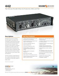
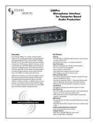
<strong>664</strong><br />
Portable Production Mixer and Recorder<br />
<strong>User</strong> <strong>Guide</strong> and Technical Information<br />
firmware rev. 1.04<br />
<strong>Sound</strong> <strong>Devices</strong>, <strong>LLC</strong><br />
E7556 State Rd. 23 and 33 • Reedsburg, WI • USA<br />
+1 (608) 524-0625 • fax: +1 (608) 524-0655<br />
Toll-Free: (800) 505-0625<br />
www.sounddevices.com<br />
support@sounddevices.com<br />
UDMA
Table of Contents<br />
Front Panel Descriptions . . . . . . . . . . . . . . . . . . . . . . . 1<br />
Left Panel Connectors and Control . . . . . . . . . . . . . . . 2<br />
Right Panel Connectors and Controls . . . . . . . . . . . . . 3<br />
Rear Panel Descriptions . . . . . . . . . . . . . . . . . . . . . . . . 4<br />
Screen Overview . . . . . . . . . . . . . . . . . . . . . . . . . . . . . . 5<br />
Main Screen . . . . . . . . . . . . . . . . . . . . . . . . . . . . . . . . . . . . . . . 5<br />
RTN Screen . . . . . . . . . . . . . . . . . . . . . . . . . . . . . . . . . . . . . . . 5<br />
Input Setup and Control . . . . . . . . . . . . . . . . . . . . . . . . 6<br />
Input Settings Screen . . . . . . . . . . . . . . . . . . . . . . . . . . . . . . . . 6<br />
Phantom Power . . . . . . . . . . . . . . . . . . . . . . . . . . . . . . . . . . . . 8<br />
Gain/Trim and Fader Relationship . . . . . . . . . . . . . . . . . . . . . . 8<br />
Input Trim (Analog)8<br />
Input Trim (Digital)8<br />
Input Fader8<br />
High-Pass Filter . . . . . . . . . . . . . . . . . . . . . . . . . . . . . . . . . . . . 9<br />
Pan Control . . . . . . . . . . . . . . . . . . . . . . . . . . . . . . . . . . . . . . . 9<br />
Input Linking . . . . . . . . . . . . . . . . . . . . . . . . . . . . . . . . . . . . . . . 9<br />
M/S Matrixing10<br />
Digital Inputs . . . . . . . . . . . . . . . . . . . . . . . . . . . . . . . . . . . . . 10<br />
Limiters . . . . . . . . . . . . . . . . . . . . . . . . . . . . . . . . . . . . . 11<br />
Metering . . . . . . . . . . . . . . . . . . . . . . . . . . . . . . . . . . . . 12<br />
Meter Ballistics . . . . . . . . . . . . . . . . . . . . . . . . . . . . . . . . . . . . 12<br />
VU12<br />
Peak + VU12<br />
Peak Only12<br />
Peak Hold12<br />
Input Activity LED . . . . . . . . . . . . . . . . . . . . . . . . . . . . . . . . . . 13<br />
Headphone Peak LED . . . . . . . . . . . . . . . . . . . . . . . . . . . . . . 13<br />
Headphone Monitoring . . . . . . . . . . . . . . . . . . . . . . . . 13<br />
Headphone Gain . . . . . . . . . . . . . . . . . . . . . . . . . . . . . . . . . . 13<br />
Headphone Source Selection . . . . . . . . . . . . . . . . . . . . . . . . 13<br />
Headphone Presets14<br />
Headphone Tones . . . . . . . . . . . . . . . . . . . . . . . . . . . . . . . . . 14<br />
PFL (Channel Solo Monitor). . . . . . . . . . . . . . . . . . . . . . . . . . 15<br />
RTN and COMM Monitoring . . . . . . . . . . . . . . . . . . . . . . . . . . 15<br />
Output Setup and Control . . . . . . . . . . . . . . . . . . . . . . 16<br />
Master and Aux Outputs . . . . . . . . . . . . . . . . . . . . . . . . . . . . 16<br />
XLR16<br />
TA3 (Master L, R, X1, and X2)16<br />
Hirose 10-pin16<br />
Direct Outputs16<br />
Tape Output16<br />
Master and Aux Bus Level . . . . . . . . . . . . . . . . . . . . . . . . . . . 17<br />
AES Digital Outputs . . . . . . . . . . . . . . . . . . . . . . . . . . . . . . . . 17<br />
COM Setup . . . . . . . . . . . . . . . . . . . . . . . . . . . . . . . . . . 17<br />
COM Send Program . . . . . . . . . . . . . . . . . . . . . . . . . . . . . . . . 18<br />
Com Program Auto-Mute . . . . . . . . . . . . . . . . . . . . . . . . . . . . 18<br />
Slate/Com Mic & Tone Oscillator . . . . . . . . . . . . . . . . 18<br />
Slate Microphone . . . . . . . . . . . . . . . . . . . . . . . . . . . . . . . . . . 18<br />
Internal Slate Mic19<br />
External Slate Mic19<br />
Tone Oscillator . . . . . . . . . . . . . . . . . . . . . . . . . . . . . . . . . . . . 19<br />
Alternate Slate/Com Switch . . . . . . . . . . . . . . . . . . . . . . . . . . 19<br />
Digital Audio Recorder . . . . . . . . . . . . . . . . . . . . . . . . 20<br />
Transport Control . . . . . . . . . . . . . . . . . . . . . . . . . . . . . . . . . . 20<br />
Recording Tracks . . . . . . . . . . . . . . . . . . . . . . . . . . . . . . . . . . 20<br />
Track Arming21<br />
Track-to-Media Routing21<br />
Track Naming22<br />
Sampling Rate . . . . . . . . . . . . . . . . . . . . . . . . . . . . . . . . . . . . 22<br />
Word Clock Synchronization23<br />
Bit Depth . . . . . . . . . . . . . . . . . . . . . . . . . . . . . . . . . . . . . . . . 23<br />
<strong>664</strong> <strong>User</strong> <strong>Guide</strong> and Technical Information<br />
Bit Depth and Dynamic Range23<br />
Recording Media . . . . . . . . . . . . . . . . . . . . . . . . . . . . . . . . . . 23<br />
Time Code . . . . . . . . . . . . . . . . . . . . . . . . . . . . . . . . . . . . . . . 24<br />
Timecode modes24<br />
Timecode Frame Rate25<br />
Jam Menu26<br />
Timecode Hold Off26<br />
F Sampling Rate Modes 26<br />
Pre-Roll . . . . . . . . . . . . . . . . . . . . . . . . . . . . . . . . . . . . . . . . . 27<br />
Synchronization . . . . . . . . . . . . . . . . . . . . . . . . . . . . . . . . . . . 27<br />
File Management . . . . . . . . . . . . . . . . . . . . . . . . . . . . . . . . . . 28<br />
File List28<br />
File Type29<br />
File Structure29<br />
Folder Options30<br />
Automatic File Splitting30<br />
Metadata Fields30<br />
<strong>Sound</strong> Reports31<br />
Take Management . . . . . . . . . . . . . . . . . . . . . . . . . . . . . . . . . 32<br />
Take List32<br />
Take Number33<br />
Scene Name33<br />
Take Notes and Phrases34<br />
Playback . . . . . . . . . . . . . . . . . . . . . . . . . . . . . . . . . . . . . . . . . 35<br />
Using a USB Keyboard . . . . . . . . . . . . . . . . . . . . . . . . 35<br />
Mixer Linking . . . . . . . . . . . . . . . . . . . . . . . . . . . . . . . . 36<br />
Linking the <strong>664</strong> With Another <strong>664</strong> or 552 Mixer . . . . . . . . . . . 36<br />
Linking to Other Mixers . . . . . . . . . . . . . . . . . . . . . . . . . . . . . 36<br />
Linking to a 302 or 44236<br />
Linking to a MixPre-D or Original MixPre37<br />
Powering . . . . . . . . . . . . . . . . . . . . . . . . . . . . . . . . . . . . 37<br />
External Powering . . . . . . . . . . . . . . . . . . . . . . . . . . . . . . . . . 37<br />
Internal Battery Powering . . . . . . . . . . . . . . . . . . . . . . . . . . . . 37<br />
Voltage Metering . . . . . . . . . . . . . . . . . . . . . . . . . . . . . . . . . . 38<br />
Power Consumption . . . . . . . . . . . . . . . . . . . . . . . . . . . . . . . . 38<br />
Storing and Recalling Settings . . . . . . . . . . . . . . . . . 39<br />
Setup Menu . . . . . . . . . . . . . . . . . . . . . . . . . . . . . . . . . 40<br />
Inputs . . . . . . . . . . . . . . . . . . . . . . . . . . . . . . . . . . . . . . . . . . . 40<br />
Outputs. . . . . . . . . . . . . . . . . . . . . . . . . . . . . . . . . . . . . . . . . . 40<br />
Limiters. . . . . . . . . . . . . . . . . . . . . . . . . . . . . . . . . . . . . . . . . . 41<br />
Recorder . . . . . . . . . . . . . . . . . . . . . . . . . . . . . . . . . . . . . . . . 41<br />
Comms/Returns . . . . . . . . . . . . . . . . . . . . . . . . . . . . . . . . . . . 42<br />
Timecode/Sync . . . . . . . . . . . . . . . . . . . . . . . . . . . . . . . . . . . 42<br />
File Storage . . . . . . . . . . . . . . . . . . . . . . . . . . . . . . . . . . . . . . 43<br />
System . . . . . . . . . . . . . . . . . . . . . . . . . . . . . . . . . . . . . . . . . . 44<br />
Quick Setup . . . . . . . . . . . . . . . . . . . . . . . . . . . . . . . . . . . . . . 45<br />
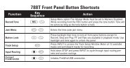
Front Panel Button Shortcuts. . . . . . . . . . . . . . . . . . . 46<br />
Connector Pin Assignments . . . . . . . . . . . . . . . . . . . 47<br />
Routing Diagram . . . . . . . . . . . . . . . . . . . . . . . . . . . . . 49<br />
Specifi cations . . . . . . . . . . . . . . . . . . . . . . . . . . . . . . . 50<br />
Analog Inputs . . . . . . . . . . . . . . . . . . . . . . . . . . . . . . . . . . . . 50<br />
Analog Outputs . . . . . . . . . . . . . . . . . . . . . . . . . . . . . . . . . . . 50<br />
Digital Outputs/Recorder . . . . . . . . . . . . . . . . . . . . . . . . . . . . 51<br />
Timecode and Sync . . . . . . . . . . . . . . . . . . . . . . . . . . . . . . . . 51<br />
Power . . . . . . . . . . . . . . . . . . . . . . . . . . . . . . . . . . . . . . . . . . . 52<br />
Environmental . . . . . . . . . . . . . . . . . . . . . . . . . . . . . . . . . . . . 52<br />
Dimensions and Weight . . . . . . . . . . . . . . . . . . . . . . . . . . . . 52<br />
Accessories . . . . . . . . . . . . . . . . . . . . . . . . . . . . . . . . 53<br />
Wave Agent . . . . . . . . . . . . . . . . . . . . . . . . . . . . . . . . . 54<br />
Declaration of Conformity . . . . . . . . . . . . . . . . . . . . . . 55<br />
Warranty and Technical Support . . . . . . . . . . . . . . . . 56<br />
v
<strong>664</strong> <strong>User</strong> <strong>Guide</strong> and Technical Information<br />
vi<br />
Copyright Notice and Release<br />
All rights reserved. No part of this publication may be reproduced, stored in a retrieval system, or transmitted in any form or by any<br />
means, electronic, mechanical, photocopying, recording, or otherwise, without the expressed written permission of SOUND DEVICES,<br />
<strong>LLC</strong>. SOUND DEVICES is not responsible for any use of this information.<br />
SOUND DEVICES, <strong>LLC</strong> shall not be liable to the purchaser of this product or third parties for damages, losses, costs, or expenses<br />
incurred by purchaser or third parties as a result of: accident, misuse, or abuse of this product or unauthorized modifi cations, repairs, or<br />
alterations to this product, or failure to strictly comply with SOUND DEVICES, <strong>LLC</strong>’s operating and installation instructions.<br />
Microsoft Windows is a registered trademark of Microsoft Corporation. Macintosh is a registered trademark of Apple Computer. Other<br />
product and company names mentioned herein may be the trademarks of their respective owners.<br />
The sound waves logo is a registered trademark of <strong>Sound</strong> <strong>Devices</strong>, <strong>LLC</strong>.<br />
v. 1.04 Features and specifications are subject to change. Visit www.sounddevices.com for the latest documentation.
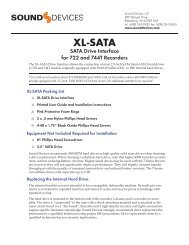
Front Panel Descriptions<br />
1<br />
4 5 6 7 8 9 10<br />
2 3<br />
19<br />
1) Input Fader<br />
Primary control for adjusting the level of an<br />
input during operation. Ranges from off to +15<br />
dB. Nominal sett ing is in the middle (0 dB).<br />
2) Gain (Trim)<br />
Coarse input gain control. Sets the initial input<br />
sensitivity level so that the Input Fader can be<br />
used for fi ne gain adjustments. Range is from<br />
+22 dB to +72 dB. See Input Setup and Control.<br />
3) Highpass Filter Control<br />
Adjusts corner (-3 dB) frequency of high-pass<br />
fi lter. Full counter-clockwise position (detented)<br />
deactivates the High-Pass Filter. Range is<br />
80-240 Hz, 12 dB/oct to 6 dB/oct. See Input Setup<br />
and Control.<br />
4) PFL / Input Select Switch<br />
Slide left : Pre-Fade Listen. Sends the input’s<br />
pre-fade signal to HP monitor mono mix. The<br />
<strong>664</strong> supports simultaneous PFL of multiple<br />
inputs. Does not aff ect Master Output signal.<br />
Slide the switch left to activate, and again to<br />
deactivate. For momentary action, hold the<br />
switch left for one second or longer. The Input<br />
LED fl ashes yellow when an input’s PFL is<br />
active. Slide right: Input Sett ings. Enters the<br />
Input Sett ings Screen where basic input setup<br />
and input-to-output bus routing is performed.<br />
See Input Setup and Control.<br />
5) Input LED<br />
Indicates input signal activity. Illuminates in<br />
various colors and intensities to show signal<br />
level and activity. Green = signal presence (prefader),<br />
yellow = limiter activity (pre- and postfade),<br />
red = signal overload/clipping (pre- and<br />
post-fade), fl ashing yellow = input PFL.<br />
18<br />
<strong>664</strong> <strong>User</strong> <strong>Guide</strong> and Technical Information<br />
17<br />
16<br />
6) Input Pan<br />
Controls the Left /Right balance of the input<br />
signal to the Stereo Master Bus.<br />
7) Transport Control<br />
Controls the Integrated Digital Recorder. Slide<br />
up to Record, press in to Pause/Stop, slide<br />
down to Play, slide left to Rewind, slide right to<br />
Fast Forward. See Digital Audio Recorder.<br />
8) Meters Button<br />
Displays the Main Screen which includes metering,<br />
fi lename, time code and other important<br />
information. Toggles to RTN Screen when<br />
pressed from Main Screen. Returns to Main<br />
Screen from any other Screen.<br />
9) LCD<br />
Displays contextual operating information and<br />
user interface.<br />
10) Internal Timecode LED<br />
When the <strong>664</strong> is powered down and timecode<br />
Mode is Freerun or 24-Hour Run, the Internal<br />
Timecode LED will fl ash blue to indicate that<br />
timecode is being maintained. The <strong>664</strong> will<br />
hold accurate timecode for 2 hours aft er being<br />
powered down.<br />
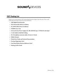
11) Power Switch<br />
Three-position slide switch, selects between AA<br />
batt ery power or external DC sources, middle<br />
position is off .<br />
12) Power LED<br />
Illuminates green to indicate the <strong>664</strong> is powered<br />
on.<br />
13) Menu Button<br />
Displays the Setup Menu.<br />
15<br />
11<br />
12<br />
13<br />
14<br />
1
<strong>664</strong> <strong>User</strong> <strong>Guide</strong> and Technical Information<br />
2<br />
14) Headphone Encoder<br />
Meter and Input Sett ings Screen: Turn to adjust<br />
headphone gain. In MaiPush to select headphone<br />
monitor source. In Menus turn to navigate.<br />
Push to make selection. In Input Sett ings<br />
Screen push to select input source.<br />
15) Headphone Clipping LED<br />
Illuminates red to indicate headphone output is<br />
approaching clipping level.<br />
16) RTN Switch<br />
Slide Left to activate RTN A, slide Right to activate<br />
RTN B. To access secondary function Press<br />
and hold Select Encoder then slide left for COM<br />
RTN and right for RTN C. Primary and Secondary<br />
functions of the RTN toggle switch can be<br />
selected in the Setup Menu.<br />
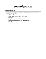
Left Panel Connectors and Control<br />
1) XLR Analog Inputs 1-6<br />
Active-balanced analog microphone- or linelevel<br />
input for inputs 1-6 on XLR connector. Input<br />
type is set within the Input Sett ings Screen.<br />
Inputs 1 and 6 can also accept AES3 or AES42<br />
signal. Pin-1 ground, pin-2 (+), pin-3 (-).<br />
17) Slate / Tone Switch<br />
Slide left to activate the Slate Microphone, slide<br />
again to deactivate. For momentary action<br />
hold for one second or longer. Slide right to<br />
activate the Tone Oscillator. Tone will latch if<br />
held for one second or longer; slide again to<br />
deactivate. Secondary function: press and hold<br />
Select Encoder then slide Mic switch to activate<br />
COM. Primary and Secondary functions can be<br />
switched in the Setup Menu.<br />
18) Slate Mic LED<br />
Illuminates green when Slate Mic or COM is<br />
active.<br />
19) Select Encoder<br />
Multi-function encoder. Selects Tracks and<br />
RTN’s on the Main and RTN Screen. On the<br />
Main Screen, press the Select Encoder and the<br />
Meters butt on to arm/disarm record tracks.<br />
With L, R, X1, X2, or any RTN selected, press<br />
then turn to adjust level. Vertical Scroll in matrix<br />
windows. Turn to adjust digital trim level<br />
in Input Sett ings Window. Turn to scroll cursor<br />
and press to insert a space character during<br />
text entry. Acts as shift butt on to access secondary<br />
functions.<br />
v. 1.04 Features and specifications are subject to change. Visit www.sounddevices.com for the latest documentation.<br />
1<br />
4 3 2<br />
2) Headphone Output<br />
1/4-inch and 3.5 mm TRS stereo headphone<br />
connectors. Can drive headphones from 8 to<br />
1000 ohm impedances to very high levels. Tip =<br />
left , ring = right, sleeve = ground.
3) Slate Mic Input<br />
TA3 input for connecting external slate microphone.<br />
Select between internal or external slate<br />
mic (with or without 12V phantom) from the<br />
Setup Menu section COMMS/RETURNS. Pin-1<br />
ground, pin-2 (+), pin-3 (-).<br />
Right Panel Connectors and Controls<br />
13<br />
<strong>664</strong> <strong>User</strong> <strong>Guide</strong> and Technical Information<br />
4) TA3 Direct Outputs 1-6 / Inputs 7-12<br />
Balanced direct outputs on TA3 connectors. Direct<br />
output signal is pre- or post-fader and level is<br />
selected between Line, -10, and Mic levels in the<br />
Setup Menu section OUTPUTS. Tone signal appears<br />
at the direct outputs. With the CL-6 Input Expander<br />
att ached, these connections can be selected as analog<br />
line inputs 7-12. Pin 1 = Ground; pin 2 = Hot (+); pin<br />
3 = Cold (-) fl oat pin 3 to unbalance.<br />
1 2 3 4 5 6 7<br />
1) USB B Connector<br />
Factory use and keyboard connection (with<br />
adapter).<br />
2) Timecode I/O<br />
Time code input and output on 5-pin LEMO®<br />
connector.<br />
3) 10-pin A and C<br />
Each connection includes a pair of transformerisolated<br />
Outputs and a stereo unbalanced<br />
Return input. Analog Output levels are selected<br />
between Line, -10, and Mic levels in Setup<br />
Menu section OUTPUTS. 10-pin A outputs can<br />
be set to AES Outputs 5,6 and 7,8 in the Setup<br />
Menu section OUTPUTS.<br />
4) Tape Output<br />
Unbalanced stereo, tape level output on TA3<br />
(Pin 1 = Ground, pin 2 = Left , pin 3 = Right) and<br />
3.5 mm (Sleeve = Ground, Tip = Left , Ring =<br />
Right) connector.<br />
12<br />
11<br />
10<br />
5) X1 and X2 Outputs<br />
Line, -10, or Mic level selected in the Setup<br />
Menu section OUTPUTS. Pin 1 = Ground,<br />
pin 2 = Hot (+), pin 3 = Cold (-) fl oat pin 3 to<br />
unbalance.<br />
6) TA3 Master Outputs<br />
Line, -10, or Mic level selected in the Setup<br />
Menu section OUTPUTS. Pin 1 = Ground,<br />
pin 2 = Hot (+), pin 3 = Cold (-) fl oat pin 3 to<br />
unbalance.<br />
7) Link I/O<br />
Used to link additional <strong>Sound</strong> <strong>Devices</strong> <strong>664</strong>, 552,<br />
302, 442, or MixPre mixers.<br />
8) Battery Compartment<br />
Holds fi ve AA (LR6) batt eries for backup powering.<br />
NiMH rechargeable cells advised.<br />
9) DC Input<br />
Accepts DC voltages from 10–18 V for powering.<br />
Pin 1 = Negative (–), pin 4 = Positive (+). Ext<br />
DC is fully isolated (fl oating) from the rest of<br />
the circuitry.<br />
9<br />
8<br />
3
<strong>664</strong> <strong>User</strong> <strong>Guide</strong> and Technical Information<br />
4<br />
10) XLR Master Outputs<br />
Transformer-balanced analog outputs on standard<br />
3-pin XLR connectors. Pin 1 = Ground;<br />
pin 2 = Hot (+); pin 3 = Cold (-). Unbalance by<br />
grounding pin 3 to pin 1. Can be set to send<br />
AES3 digital signals (1,2 and 3,4 on L and R<br />
respectively) in Setup Menu section OUTPUTS.<br />
11) RTN B Input<br />
Unbalanced stereo 3.5 mm female connector for<br />
Return B audio input. Sleeve = Ground, Tip =<br />
Left , Ring = Right.<br />
12) CompactFlash Slot<br />
Accepts approved CompactFlash cards with the<br />
label-side toward the rear of the <strong>664</strong>. Compatible<br />
with Type I and Type II cards. High-speed<br />
UDMA cards are recommended for higher<br />
track count recording.<br />
13) SD Card Slot<br />
Accepts SD/SDHC/SDXC cards with the<br />
notched corner oriented toward the top of the<br />
<strong>664</strong>. High speed class 10 cards are recommended.<br />
Insert until it clicks securely in the slot. The<br />
card should glide smoothly into the slot. Push<br />
to eject.<br />
Visit www.sounddevices.com/approved for an up-to-date list of tested and approved cards.<br />
Rear Panel Descriptions<br />
1 2<br />
1) BNC Word Clock Input<br />
Accepts word clock rates between 32 kHz and<br />
48.048 kHz for synchronizing the internal recorder<br />
to external digital audio devices.<br />
2) BNC Word Clock Output<br />
Provides word clock signal to synchronize<br />
external digital audio devices to the <strong>664</strong>.<br />
v. 1.04 Features and specifications are subject to change. Visit www.sounddevices.com for the latest documentation.<br />
4<br />
3) TA3 COM Send<br />
Unbalanced, stereo, line-level output. Program<br />
assigned to COM output from Setup Menu.<br />
4) TA3 COM Return<br />
Line-level input for return feed from on-set<br />
communications sources.<br />
3
Screen Overview<br />
Main Screen<br />
<strong>664</strong> <strong>User</strong> <strong>Guide</strong> and Technical Information<br />
The Main Screen displays important information at-a-glance. The Main Screen can be accessed quickly<br />
from any other screen by pressing the Meters butt on.<br />
Display of the sample rate information and timecode frame rate information can be “swapped” by holding the<br />
Meters butt on and Sliding the RTN Switch to the left .<br />
Bus tracks<br />
Armed track<br />
Input tracks<br />
Unarmed track<br />
SMPTE Timecode<br />
RTN Screen<br />
Current take Media information<br />
Absolute recording time<br />
Power source level<br />
Sample rate information RTN levels<br />
When the Meters butt on is pressed from the Main Screen, the RTN Screen is shown.<br />
Bus tracks<br />
RTN during gain adjustment<br />
Return inputs<br />
SMPTE Timecode<br />
Absolute recording time<br />
Monitor (Headphone) information<br />
Timecode frame rate Time and date<br />
Return gain (during adjustment)<br />
5
<strong>664</strong> <strong>User</strong> <strong>Guide</strong> and Technical Information<br />
6<br />
Input Setup and Control<br />
The <strong>664</strong> has six, full-featured audio inputs on XLR connectors (six additional inputs on TA3 connectors<br />
with the optional CL-6 Input Expander att ached). Each analog input has a wide gain range to accommodate<br />
nearly all signal types, from microphones to line-level sources. Inputs can be used as either<br />
balanced or unbalanced connections. To unbalance, tie pin-3 to pin-1 of the XLR connector. There is no<br />
change in gain between unbalanced and balanced connections into the <strong>664</strong>.<br />
Input Settings Screen<br />
Each input’s sett ings are accessed through its Input Sett ings Screen. To access the Input Sett ings screen<br />
for an input, slide the Input Selector Switch to the right. The LCD will display information pertaining<br />
to the selected input and provide access to.<br />
Input/Track Number<br />
2) Input Meter<br />
Current Fader Gain<br />
1) ISO Track Status<br />
4) Aux Bus Assignment<br />
1) ISO Track Status<br />
input/Track Name<br />
6) Input Polarity<br />
3) Input Selection<br />
Headphone Source / Level<br />
5) LR Bus Assignment<br />
Displays the status of the Input’s dedicated Iso Track on the recorder. Each input is permanently<br />
routed to its Iso track. To select whether an input is routed pre- or post-fade, push the Select Encoder,<br />
turn it to make a selection, and push it again to confi rm the selection.<br />
The background color of the Iso Track Status box indicates the status of the Input’s Iso Track. A blue<br />
background indicates that the Iso Track is not active and will not be recorded. A red background indicates<br />
the Iso Track is armed for recording.<br />
2) Input Meter<br />
Displays the Input’s signal level and limiting activity. The level displayed is the level to the Iso Track<br />
and will be pre- or post-fade depending on the Iso Track Status. Meter ballistics can be set globally<br />
from VU or Peak+VU in Setup Menu item SYSTEM > Meter Ballistics.<br />
v. 1.04 Features and specifications are subject to change. Visit www.sounddevices.com for the latest documentation.
3) Input Selection<br />
<strong>664</strong> <strong>User</strong> <strong>Guide</strong> and Technical Information<br />
Displays the available input types. To change the input type, push the Headphone Encoder, turn it to<br />
make a selection, and push it again to confi rm the selection.<br />
Input Type Description<br />
Off Input off.<br />
MIC Use with dynamic microphones or other mic-level signals.<br />
MIC-PH Use with phantom-powered condenser microphones only. Provides 48V or 12V phantom power.<br />
see Phantom Power<br />
LINE For use with any line-level source.<br />
LINE-PH For use with phantom-powered condenser microphones only. Provides 48V or 12V phantom<br />
power, but at a line-level gain range. Useful for recording extremely loud sounds.<br />
AES42 Digital input with power activated for digital microphones, inputs 1, 2, 5, and 6 only.<br />
AES3 Digital input, inputs 1, 2, 5, and 6 only<br />
AES42 and AES3 option only appears in input 2 when selected in input 1, and only appears in input 5 when<br />
selected in input 6. Channel 1 and Channel 6 XLR connectors are used for digital inputs.<br />
4) Aux Bus Assignment<br />
Displays the status of the Input’s assignment to the X1 and X2 Output Buses. Inputs 2 through 5 can<br />
only be routed to X1 and X2 post-fade, while Inputs 1 and 6 can be routed to X1 and X2 pre- or postfade.<br />
Slide the Slate / Tone Switch left for the X1 Track and right for the X2 Track to cycle through the<br />
available options.<br />
5) LR Bus Assignment<br />
Displays the status of the Input’s assignment to the main Left and Right Output Buses. Inputs routed<br />
to the Left and Right Output Bus are always post-fader and post-pan. To add or remove the Input<br />
from the Left and Right Output Bus, slide the RTN Switch to the right.<br />
6) Input Polarity (Inputs 2, 4, and 6)<br />
Polarity reversal is used to compensate for incorrectly wired balanced cables, to prevent signal cancellation<br />
when a source is dual-miked from opposite directions, or to reverse left /right with microphones<br />
in a mid-side (MS) confi guration.<br />
7
<strong>664</strong> <strong>User</strong> <strong>Guide</strong> and Technical Information<br />
8<br />
Phantom Power<br />
Phantom powering is a fi xed DC voltage of either 12 or 48 Volts. This voltage is resistively applied to<br />
pin 2 and pin 3 of an input’s XLR connector, relative to pin 1. In this confi guration, there is no voltage<br />
diff erence between signal pins 2 and pin 3.<br />
The phantom voltage is selectable between 12 and 48 Volts from the Setup Menu item<br />
INPUTS > Phantom Voltage. The selected voltage level applies to all inputs with phantom power<br />
enabled. The factory default phantom power voltage is 48 V.<br />
Phantom power can be activated for each input. To enable phantom power, enter the input’s channel<br />
screen, press the Headphone Controller, highlight either MIC-PH or LINE-PH, press Headphone Controller<br />
again to make the selection.<br />
Gain/Trim and Fader Relationship<br />
The gain of an input is adjusted by two controls, Input Trim and Input Fader. This two-stage architecture<br />
is identical to the topology of large mixing consoles and provides a great deal of control. Input<br />
Trim is oft en thought of as a course gain control and the Input Fader as the fi ne gain control.<br />
Input Trim (Analog)<br />
The <strong>664</strong>’s analog input sensitivity is set with the pop-up Trim control<br />
knob. With the Input Fader set to unity gain (0 dB or 12 o’clock), make<br />
the appropriate adjustments using the Trim control. Once the coarse gain<br />
is set to the desired level, push the Trim control to hide it from the <strong>664</strong>’s<br />
mixing surface. Analog trim level is adjustable from +22 to +72 dB of gain.<br />
Input Trim (Digital)<br />
The coarse level of a digital input is set by rotating the Select Encoder in<br />
the Input Sett ings Screen of an input with a digital source. The digital<br />
trim level is displayed on the LCD when adjusted. The digital trim level is<br />
adjustable from -20 to +50 dB.<br />
Input Fader<br />
The Input Fader is the primary control used while mixing and it aff ects<br />
the level of the Input signal routed to all post-fade destinations. Use the<br />
Input Fader to make fi ne gain adjustments. The fader can be att enuated<br />
from off (full counter-clockwise position) to +15 dB above the set Trim<br />
level (full clockwise position). To optimize gain structure for the best performance,<br />
operate input faders at or near the 0 dB (unity gain) position.<br />
v. 1.04 Features and specifications are subject to change. Visit www.sounddevices.com for the latest documentation.
High-Pass Filter<br />
<strong>664</strong> <strong>User</strong> <strong>Guide</strong> and Technical Information<br />
Each input channel has an adjustable high-pass fi lter controlled by the High-Pass Filter control. Highpass<br />
(or low-cut/low roll-off ) fi lters are useful for removing excess low<br />
frequency energy from audio signals. Wind noise is a common unwanted<br />
low frequency signal that can be reduced with the use of a high-pass fi lter.<br />
For most audio applications, engaging the high-pass fi lter is benefi cial, because<br />
audio information below 100 Hz is rarely used, especially for speech<br />
reproduction.<br />
The <strong>664</strong>’s high-pass fi lter circuit features an adjustable corner (-3 dB) frequency<br />
over a range from 80 to 240 Hz. Below 80 Hz, the fi lter’s slope is 12<br />
dB/octave. At higher corner frequency sett ings, the slope is 6 dB/octave. The<br />
purpose for this compound slope is to give additional roll-off at the 80 Hz<br />
sett ing to reduce wind noise and low frequency rumble. The higher sett ings<br />
can be used to counteract the proximity eff ect of directional microphones where a more gentle slope is<br />
desired.<br />
The <strong>664</strong>’s high-pass fi lter circuit is unique because of its placement before any electronic amplifi cation.<br />
Most mixers’ high-pass fi lter circuits are placed aft er the microphone preamplifi er, such that all of the<br />
low-frequency signals get amplifi ed. By virtue of the <strong>664</strong>’s circuit cutt ing the low-frequency signals<br />
before amplifi cation, higher headroom is achieved in the presence of signals with signifi cant lowfrequency<br />
energy.<br />
When possible, att empt to equalize at the sound source with microphone selection, placement, windscreens,<br />
and onboard microphone fi ltering. Many microphones have on-board high pass fi lters. Use<br />
the high-pass fi lters on the <strong>664</strong> in conjunction with the microphone’s fi lter to increase the fi lter’s slope.<br />
The fi lter can be removed from the circuit completely by rotating the high-pass fi lter control to the full<br />
counter-clockwise (detented) position. The high-pass fi lter potentiometer can be adjusted easily and<br />
then recessed to hide it from the mixing surface.<br />
Pan Control<br />
The pop-up Pan Control routes inputs to the left (L) and right (R)<br />
channels of the stereo Master Bus. The pan pot has a detent in the<br />
center position. Aft er sett ing the pan, the pan control can be recessed<br />
to hide it from the mixing surface during normal operation.<br />
Input Linking<br />
Input pairs 1-2, 3-4, and 5-6 can be linked as stereo pairs. When a pair of inputs is linked:<br />
• Each channels’ Trim Control and High-Pass Filter Control work as normal, controlling coarse gain<br />
and high-pass fi ltering for their respective inputs.<br />
• The odd channel’s Input Fader controls the post-fade level of both inputs.<br />
• The odd channel’s Pan Control controls the balance of the stereo signal to the Master Bus. When<br />
linked MS, the odd channel’s Pan Control functions as a left /right balance control for the matrixed<br />
MS signal.<br />
9
<strong>664</strong> <strong>User</strong> <strong>Guide</strong> and Technical Information<br />
10<br />
• The even channel’s Fader Control and Pan Control are disabled.<br />
• The limiters of both inputs are linked.<br />
• The background label of both inputs is connected on the Main Screen.<br />
M/S Matrixing<br />
Linked<br />
Unlinked<br />
When input pairs are linked MS, the odd channel is used for the Mid signal and the even channel is<br />
used for the Side signal. To produce a stereo signal from an M/S confi guration, the signal from both<br />
microphones must be processed.<br />
Mid-side (MS) matrixing is a method for processing audio signal from a cardioid microphone and a bidirectional<br />
microphone into a stereo signal. The cardioid microphone is the “mid” signal and connects<br />
to the odd Input, and the bidirectional microphone is the “side” signal and connects to even Input.<br />
The cardioid microphone is pointed at the sound source, and the bidirectional microphone is oriented<br />
sideways (positioned with its capsule as near as possible to the cardioid microphone’s capsule). The<br />
following diagram shows the relative polar patt erns of microphones in an M/S confi guration.<br />
Digital Inputs<br />
Mid Signal<br />
Side Signal<br />
The <strong>664</strong> accepts AES3 (AES/EBU) balanced, AES42 (digital microphone) balanced, and AES3id unbalanced<br />
digital signals on the Input 1 and Input 6 XLR connectors. The <strong>664</strong> auto-detects between AES3<br />
and AES3id digital signals and adjust accordingly. Digital input gain is controlled from the front panel<br />
faders.<br />
Never att ach unbalanced connections to an input set for AES42. This can result in damage to the hardware.<br />
To use a digital input, slide the Input 1 or Input 6 Input Selector Switch to the right to enter the Input<br />
Sett ings Screen. Press the Headphone Encoder to display the list of available input sources. Turn<br />
the Headphone Encoder to select AES3 or AES42, and press the Headphone Encoder to confi rm the<br />
selection.<br />
v. 1.04 Features and specifications are subject to change. Visit www.sounddevices.com for the latest documentation.
<strong>664</strong> <strong>User</strong> <strong>Guide</strong> and Technical Information<br />
Each connector carries two channels of digital audio. Alternate channels of digital audio sent to Input<br />
1 or Input 6 are available on adjacent inputs, according to the following table.<br />
AES Input Channel: Available to <strong>664</strong> Input:<br />
XLR Input 1, Left Channel Input 1<br />
XLR Input 1, Right Channel Input 2 (Available when Input 1 source is set to AES)<br />
XLR Input 6, Left Channel Input 5 (Available when Input 6 source is set to AES)<br />
XLR Input 6, Right Channel Input 6<br />
The <strong>664</strong>’s digital inputs are sample rate converted to the internal recorder’s sample rate. To sync the<br />
sample rate of the <strong>664</strong>’s internal recorder to external digital audio devices, see Sampling Rate.<br />
Things to consider when using AES digital inputs:<br />
• When using an unbalanced AES3 (SPDIF) input, the other available digital input should not be<br />
used with an AES42 microphone.<br />
• Signal from digital inputs is not available on direct outputs.<br />
Limiters<br />
Limiters prevent clipping by att enuating signals that surpass a set threshold. The amount of att enuation<br />
is defi ned by the “ratio” of the limiter and expressed as two numbers. All <strong>664</strong> limiters use a 20:1<br />
compression ratio. This means that signal that exceeds the threshold by 20 dB will exit the limiting<br />
stage at only 1 dB above the threshold.<br />
The time it takes for limiting to begin once signal has exceeded the threshold is referred to as the “attack<br />
time” and the time it takes for limiting to cease once signal has fallen back below the threshold is<br />
referred to as “release time”. Signals that exceed the threshold faster than the limiter’s att ack time can<br />
still cause clipping. The <strong>664</strong> limiters have a 1 ms att ack time and a 500 ms release time.<br />
The limiters are globally activated when the Setup Menu item LIMITERS > Limiters is set to On. This<br />
activates both the input limiters (Inputs 1 through 6) and all output limiters. <strong>Sound</strong> <strong>Devices</strong> recommends<br />
using the limiters at all times. Limiters are present on both mic and line-level inputs as well as<br />
the Master L,R tracks and the X1,X2 tracks. The <strong>664</strong> input limiters have a threshold of +16 dBu (4 dB<br />
below clipping), while the limiters for the L, R, X1, and X2 tracks are adjustable from the Setup Menu<br />
item OUTPUTS > L,R Limiter Thresh and OUTPUTS > X1,X2 Limiter Thresh.<br />
In normal operation, with a properly set gain structure, the threshold of the Input Limiter is rarely<br />
reached. Without Input Limiters, high signal conditions can overload a channel and cause distortion.<br />
The Input limiter is working when the respective input’s Input Activity LED illuminates yellow. If the<br />
11
<strong>664</strong> <strong>User</strong> <strong>Guide</strong> and Technical Information<br />
12<br />
Activity LED is regularly in the yellow, reduce the amount of gain applied to the channel by turning<br />
down the Trim control. See Input Activity LED for additional information.<br />
When Inputs are linked as a stereo pair, the Input Limiters are also linked and perform the same gain<br />
reduction equally to both inputs.<br />
The Output Limiters prevent the L,R and X1,X2 signal from exceeding the user-set limiter threshold.<br />
Setup Menu options LIMITERS > L,R Limiter Thresh and LIMITERS > X1,X2 Limiter Thresh allow<br />
limiter thresholds to be set set in 1 dB increments from +4 dBu to +20 dBu.<br />
Metering<br />
All track levels are displayed on the LCD in the Main Screen. RTN input levels are displayed on the<br />
RTN Screen (Press the Meters butt on to toggle between the RTN Screen and the Main Screen). Each<br />
segment of the meter represents 1 dB. A larger red square under the 20 dBU marker indicates clipping<br />
on the track. A large yellow square indicates limiting activity on the track.<br />
Meter Ballistics<br />
VU<br />
Input clipping<br />
Limiter active<br />
VU (volume units) meter ballistics correspond closely to how the human ear perceives loudness. This<br />
provides a good visual indication of how loud a signal will be. In VU mode, the att ack and decay of<br />
the meter signal is 300 mS. VU meters provide good visual indication of how loud a signal will be, but<br />
provide poor information of actual signal peaks.<br />
Peak + VU<br />
The <strong>664</strong> can simultaneously display VU and Peak level information. In this mode the perceived loudness<br />
(VU) is displayed as a standard bar, and the Peak signal as a single, independent segment above<br />
the VU.<br />
Peak Only<br />
Peak-reading ballistics (PPM) correspond to actual signal peaks, but don’t necessarily correspond to<br />
perceived signal loudness. Peak meters have an instantaneous att ack and a slow decay to allow visual<br />
monitoring of peak activity. Peak metering is useful when interconnecting to audio inputs on digital<br />
equipment. In the digital realm, signal overload can cause immediate distortion.<br />
Peak Hold<br />
When Peak Metering is enabled (Peak Only or Peak + VU), peak hold displays the last highest peak<br />
value on the meter as a separate, individual meter segment. By default this meter segment will remain<br />
visible for 1 second. This time can be adjusted to 1, 2, 3, 4, or 5 seconds. The Infi nity option will display<br />
the last highest peak indefi nitely until a higher peak is reached. The Off option will disable peak hold.<br />
The Peak Hold sett ing applies to meters on the Main Screen and in all Input Sett ings windows.<br />
v. 1.04 Features and specifications are subject to change. Visit www.sounddevices.com for the latest documentation.
Input Activity LED<br />
Each Input has its own Input Activity LED located just above the Input Fader.<br />
The LED illuminates in various colors and intensities to represent the signal<br />
level appearing at its respective input. Green = pre-fade signal activity, yellow<br />
= pre- and post-fader limiter activity, red = pre- and post-fader signal overload<br />
(peaking). Reduce the trim level control if the LEDs continuously illuminate<br />
yellow or red. The Input Activity LED will fl ash yellow when the Input PFL is<br />
latched. see PFL.<br />
Headphone Peak LED<br />
The Headphone Peak LED is located just left of the Headphone Encoder.<br />
This LED will illuminate red to indicate clipping in the headphone amplifi er.<br />
Monitoring without a visual indication of headphone clipping can mislead the<br />
sound mixer into thinking that the output or return feeds are distorted.<br />
Headphone Monitoring<br />
Headphone Gain<br />
<strong>664</strong> <strong>User</strong> <strong>Guide</strong> and Technical Information<br />
Headphone output level is controlled by turning the Headphone Encoder while viewing the Main<br />
Screen or Input Sett ings Screen. When adjusting the headphone gain, the gain value (in dB) is displayed<br />
in the lower right corner of the LCD (Near the Headphone Encoder). This space displays the<br />
currently selected headphone source when the headphone gain is not being adjusted.<br />
Headphone gain during adjustment<br />
Headphone Encoder<br />
The <strong>664</strong> can drive headphones to dangerously high volumes. Turn down the headphone gain before<br />
selecting a headphone source to prevent accidental signal extremes.<br />
Headphone Source Selection<br />
To select the monitor source, push the Headphone Encoder while viewing the Main Screen to display<br />
the Monitor Source List. This will display a list of available monitor sources. Turn the Headphone<br />
13
<strong>664</strong> <strong>User</strong> <strong>Guide</strong> and Technical Information<br />
14<br />
Encoder to highlight a source, and press the Headphone Encoder to select that source. The signal to<br />
the headphone outputs will immediately change to the selected program.<br />
Monitor Source Description<br />
LR ST Master Bus in stereo.<br />
LR Mono Master Bus summed mono to both ears.<br />
L Mono Left channel of Master Bus sent to both ears.<br />
R Mono Right channel of Master Bus sent to both ears.<br />
LR MS ST Mid-Side Stereo - Master Bus decoded MS stereo to headphones, this is not to be used if the inputs<br />
are already linked as an MS pair.<br />
X1X2 Aux Bus in stereo.<br />
HP Preset HP Presets 1-10 are customizable monitor sources. See Headphone Presets<br />
Headphone Presets<br />
Ten custom monitor sources are available. These headphone presets can be edited, named and saved.<br />
To edit a custom headphone preset, press the Headphone Encoder to access the Monitor Source List,<br />
highlight the desired preset, then slide the Slate/Tone Switch. This displays the Headphone Preset<br />
Screen:<br />
Highlighter<br />
HP Preset name<br />
Assigned source Unassigned source<br />
MS decoding Mono summing<br />
Available sources are displayed for each monitor channel (left and right). Sources with a blue background<br />
are assigned to that channel of the headphones, and sources with a black background are not<br />
assigned to the headphone channel. To toggle the assignment of a source, turn the Headphone Encoder<br />
to highlight the source and press the Headphone Encoder to toggle the assignment.<br />
Slide the RTN Switch left to toggle MS decoding for the preset. MS decoding will decode the entire<br />
preset and should not be used if inputs are already linked MS. Slide the RTN Switch right to togglemono<br />
summing of the preset. Mono summing will ignore left and right assignment and put all active<br />
sources in both channels of the preset.<br />
When the Headphone Preset is edited, it can be named so it can be easily identifi ed in the Monitor<br />
Source List. To name a Headphone Preset, slide the Slate / Tone Switch either left or right while viewing<br />
the Headphone Preset Screen.<br />
Headphone Tones<br />
The start of a recording is indicated audibly by a single 440 Hz tone sent to headphones. When<br />
recording is stopped two 220 Hz tones are sent to the headphones. The Record/Stop Bell can<br />
be enabled from the Setup Menu item SYSTEM > Record/Stop Bell. The Setup Menu option<br />
SYSTEM > Warning Bell Level allows adjustment of the level of the Record/Stop Bell.<br />
v. 1.04 Features and specifications are subject to change. Visit www.sounddevices.com for the latest documentation.
PFL (Channel Solo Monitor)<br />
Slide the PFL switch left to activate, and again to deactivate. For momentary<br />
action, hold the switch left for one second or longer.<br />
PFL stands for “Pre-Fade Listen”. When any input’s PFL is activated, the<br />
currently selected Monitor Source is replaced with the PFL mix program.<br />
The PFL mix program is a mono mix of the pre-fade level of all inputs<br />
with PFL enabled. PFL monitoring only aff ects the headphone monitor, it<br />
does not aff ect audio sent to the outputs.<br />
The selected input’s Activity LED fl ashes yellow when the input’s PFL is<br />
engaged. When one input PFL is engaged, that input’s name will appear<br />
in the lower right corner of the Main Screen. When multiple input PFL’s<br />
are engaged, PFL MULT will appear in the lower right corner of the Main<br />
Screen.<br />
RTN and COMM Monitoring<br />
<strong>664</strong> <strong>User</strong> <strong>Guide</strong> and Technical Information<br />
RTN A, RTN B, RTN C, and COM RTN inputs can be monitored quickly using the RTN Switch.<br />
Primary Monitor Sources are monitored by sliding the RTN Switch left or right while Alternate<br />
Monitor Sources are monitored by holding the Select Encoder then sliding the RTN Switch left or<br />
right. The Primary and Alternate Monitor Sources can be changed from the Setup Menu options<br />
COMMS/RETURNS > RTN Toggle Left and COMMS/RETURNS > RTN Toggle Right. To return to the<br />
previous monitor selection, Slide the RTN Switch in the same direction of the active RTN.<br />
RTN A, RTN B, and RTN C input levels can be metered and adjusted from the RTN Screen. To access<br />
the RTN Screen, press the Meters Butt on when viewing the Main Screen. To adjust the gain of a RTN<br />
input:<br />
1. Access the RTN Screen, if it is not visible already.<br />
2. Turn the Select Encoder to highlight the RTN to be adjusted.<br />
3. Press the Select Encoder to access gain adjustment mode for the selected RTN. The background<br />
color of the RTN label will become orange, and the input gain value (in dB) will appear<br />
in the lower left corner of the LCD.<br />
4. Turn the Select Encoder to adjust the gain. RTN gain adjustment mode will exit automatically<br />
aft er 3 seconds.<br />
RTN during level adjustment<br />
RTN monitoring will cancel the PFL mix program when activated.<br />
Input gain of RTN A (during adjustment)<br />
15
<strong>664</strong> <strong>User</strong> <strong>Guide</strong> and Technical Information<br />
16<br />
Output Setup and Control<br />
The <strong>664</strong> features a host of analog and digital outputs to accommodate for complex, multi-camera setups.<br />
The <strong>664</strong> has 2 stereo output busses: The Master Bus (LR), and the Aux Bus (X1/X2).<br />
Master and Aux Outputs<br />
There are 4 pairs of balanced analog output connections for the Master Bus (XLR, TA3, and 2 Hirose<br />
10-pin), and one pair of balanced analog output for the Aux Bus (TA3). Additionally, there are two<br />
stereo unbalanced outputs for the Master Bus (TA3 and 3.5mm Tape Outputs).<br />
The XLR and both Hirose 10-pin outputs are transformer-balanced, each driven from their own transformer<br />
windings for excellent isolation. Each output can be independently set to Line (+4 dBu nominal),<br />
-10, or Mic level (40 dB of attenuation versus Line) from the Setup Menu section OUTPUTS. The<br />
master outputs are capable of driving long cable runs.<br />
XLR<br />
By default the XLR outputs send a balanced analog signal. These connections can be independently<br />
confi gured to send AES3 signal. see AES Digital Outputs for details. When set to analog output, the L<br />
and R XLR connections always carry the Left and Right Master Bus program.<br />
TA3 (Master L, R, X1, and X2)<br />
The TA3 outputs send a balanced analog signal. The X1 and X2 TA3 connections always carry X1<br />
and X2 Aux bus program. The L and R TA3 connections always carry the Left and Right Master Bus<br />
program.<br />
Hirose 10-pin<br />
Each Hirose 10-pin connection has a balanced pair of outputs that carry the Left and Right Master bus<br />
program. By default, each of the balanced outputs on the Hirose 10-pin connections sends a balanced<br />
analog signal. Each of the balanced outputs on the 10-pin A connections can be independently confi gured<br />
to send AES3 signal. see AES Digital Outputs for details.<br />
Each Hirose 10-pin also includes an unbalanced stereo return input for headphone monitoring. The<br />
<strong>Sound</strong> <strong>Devices</strong> XL-10 Breakout Cable is an available accessory that provides easy access to the balanced<br />
outputs and stereo returns of the 10-pin Hirose connections.<br />
Direct Outputs<br />
Inputs 1-6 have corresponding direct outputs on balanced TA3 connections. By default, these outputs<br />
are pre-fade and line level. The direct outputs can be set to post-fade from the Setup Menu item<br />
OUTPUTS > Direct Out Pre/Post. The direct outputs can be set to Line (+4 dBu nominal), -10, or Mic<br />
level (40 dB of attenuation versus Line) from the Setup Menu item OUTPUTS > Direct Out Levels.<br />
AES digital input signals are not available on direct outputs.<br />
Tape Output<br />
The <strong>664</strong> includes two unbalanced tape level outputs, a TA3 connector and a 3.5 mm jack. These two<br />
connectors are resistively in parallel and are isolated from the balanced outputs.<br />
Tape Outputs, by default, send the Left and Right stereo program. The Tape outputs can be used to<br />
send the incoming RTN A, RTN B, or RTN C signals directly to receiving devices from Setup Menu<br />
v. 1.04 Features and specifications are subject to change. Visit www.sounddevices.com for the latest documentation.
<strong>664</strong> <strong>User</strong> <strong>Guide</strong> and Technical Information<br />
option OUTPUTS > Tape Out Source. This is useful for sending an IFB wireless feed of the RTN audio<br />
to the producer for video playback.<br />
Master and Aux Bus Level<br />
The output gain of the Master Bus and the Aux Bus is adjustable from Off , -30 to 0dB. To adjust output<br />
gain:<br />
1. From the Main Screen, turn the Select Encoder to highlight the output(s) to be att enuated.<br />
2. Push the Select Encoder. The output level of the highlighted track will be displayed in the<br />
lower right-hand corner of the LCD. If no adjustment is made before 3 seconds, the selection will<br />
cancel. This is to avoid accidental adjustments.<br />
3. Turn the Select Encoder to adjust the gain.<br />
Outputs that are linked (from Setup Menu item OUTPUTS > Linking) will be shown as a connected<br />
box on the Main Screen and their gain will be adjusted simultaneously.<br />
AES Digital Outputs<br />
There is a total of 8 available channels of digital output on 4 connections. Each of the XLR or 10pin<br />
A outputs can be confi gured to output AES3 digital signals from the Setup Menu options<br />
OUTPUTS > XLR-R Out, OUTPUTS > XLR-L Out, and OUTPUTS > 10-pin A Out.<br />
Any track can be routed to any AES output in any combination. The AES output routing can be edited<br />
from the Setup Menu item OUTPUTS > AES Output Routing. This interface consists of a matrix in<br />
which the columns are tracks and the rows are the numbered AES outputs. The blue boxes indicate<br />
routed tracks and the black boxes indicate unrouted tracks. Turn the Select Encoder to move the<br />
orange highlighter vertically and turn the Headphone Encoder to move the highlighter horizontally.<br />
Push either the Select Encoder or the Headphone encoder to toggle the routing status of the highlighted<br />
track.<br />
The following screen shot shows the AES Output Routing screen. The highlighter is in the lower-left<br />
corner.<br />
COM Setup<br />
The <strong>664</strong> features an unbalanced stereo COM Send (TA3) and an balanced mono COM RTN (TA3) for<br />
communications purposes. These special input and output channels can be used to privately communicate<br />
with a boom operator or other member of the production crew.<br />
17
<strong>664</strong> <strong>User</strong> <strong>Guide</strong> and Technical Information<br />
18<br />
During operation, it is possible to interrupt the Com signal and speak to the boom operator via the<br />
slate mic by Holding down the Select Encoder and sliding the Slate/Tone Switch to the left. The green<br />
Slate LED will illuminate to indicate that the slate mic is routed to the Com Send. During this time, the<br />
slate mic signal is sent only to the Com Send Output and right Headphone output, but not to record<br />
tracks or any other outputs. To cancel slate communication and resume the Com Program, slide the<br />
Slate/Tone Switch to the left again. The green Slate LED will turn off.<br />
The gain of the Com Send and Com Return can be adjusted from the Setup Menu options<br />
COMMS/RETURNS > Com Send Gain and COMMS/RETURNS > Com Return Gain, respectively.<br />
COM Send Program<br />
By default, the program sent to the COM Send output is the Left and Right Stereo Bus. To change the<br />
program of the COM Send:<br />
1. Enter the Setup Menu and select COMMS/RETURNS.<br />
2. Select the Com Send Program Option.<br />
3. Turn the Headphone Encoder to select the desired source, and push the Headphone Encoder<br />
to toggle the assignment of the source to the Left or Right side of the COM Send.<br />
4. Optionally, slide the RTN switch to toggle mono or stereo of the COM Send.<br />
Com Program Auto-Mute<br />
By default, the Com Send program will mute when slate communication is engaged. This helps<br />
the boom operator hear the voice of the <strong>664</strong> operator. This behavior can be disabled so that the<br />
Com Send program is not muted when communication is engaged via the Setup Menu option<br />
COMMS/RETURNS > Program Auto-Mute.<br />
Slate/Com Mic & Tone Oscillator<br />
The 3-position Slate / Tone Switch controls both the slate microphone and the tone oscillator.<br />
Slate Microphone<br />
Push the Slate / Tone Switch left to activate the slate mic. The green Slate Mic LED will illuminate to<br />
indicate that the slate mic is active. Push the Slate / Tone Switch left again to deactivate the slate mic.<br />
Hold the Slate / Tone Switch left for 1 second to activate the slate mic momentarily (until the switch is<br />
released).<br />
v. 1.04 Features and specifications are subject to change. Visit www.sounddevices.com for the latest documentation.
<strong>664</strong> <strong>User</strong> <strong>Guide</strong> and Technical Information<br />
The secondary slate function is accessed by holding down the Select encoder when using the Slate<br />
/ Tone Switch. By default, the secondary slate function activates the slate mic to the COM Send (see<br />
COM Setup). The primary and secondary slate functions can be swapped from the Setup Menu option<br />
COMMS/RETURNS > Mic Toggle Switch.<br />
Program audio is muted when the slate mic is activated. This behavior can be disabled (so that<br />
program audio does not mute when the slate mic is activated) from the Setup Menu option<br />
COMMS/RETURNS > Program Auto-Mute.<br />
Internal Slate Mic<br />
The default slate mic is the <strong>664</strong>’s internal slate microphone. The <strong>664</strong>’s built-in slate microphone is used<br />
to notate scenes from the mixer location. Its audio performance is not suitable for critical recording applications;<br />
it should be used for documenting scenes and for communication purposes only.<br />
External Slate Mic<br />
An external microphone can be used instead of the built-in slate microphone. To use an external<br />
slate mic, plug the mic into the TA3 Slate Mic input on the Left panel and adjust Setup Menu option<br />
COMMS/RETURNS > Slate/Com Mic Source to Ext Mic (for dynamic microphones) or Ext 12V Mic<br />
(for condenser microphones).<br />
Tone Oscillator<br />
Push the Slate / Tone Switch right to activate the tone oscillator. Hold the Slate / Mic Switch right for<br />
more than 1 second to lock the tone oscillator on. When the tone oscillator is locked on, push the Slate<br />
/ Mic Switch right again to deactivate.<br />
By default, tone will be sent to the Master Bus (L,R), its associated outputs, and all direct outs. Tone<br />
can additionally sent to the X1 and/or X2 tracks. Access Setup Menu option SYSTEM > Tone Routing<br />
to adjust this.<br />
Alternate Slate/Com Switch<br />
By default, COM communication is engaged by sliding the Slate/Tone Switch to the left<br />
while holding the Select Encoder and normal slate operation is engaged by simply sliding the<br />
Slate/Tone Switch to the left. This functionality can be reversed from the Setup Menu option<br />
COMMS/RETURNS > Mic Toggle Switch.<br />
19
<strong>664</strong> <strong>User</strong> <strong>Guide</strong> and Technical Information<br />
20<br />
Digital Audio Recorder<br />
The <strong>664</strong> features a powerful multi-track digital recorder. The internal recorder can record up to 10<br />
tracks (16 tracks with the optional CL-6 Input Expander. see CL-6) of uncompressed PCM audio (.WAV<br />
fi le extension) or 2 tracks of compressed MP3 audio (.MP3 fi le extension). See File Formats. Data is written<br />
to removable CompactFlash (CF) and SD/SDHC/SDXC (SD) cards. See Record Media.<br />
Transport Control<br />
The 5-position Transport Control is used to perform all recording and playback functions.<br />
Function Direction Action<br />
Record Push the Transport Control Up<br />
Begins recording a new file.<br />
Pause / Stop Press the Transport Control<br />
During Record, press once to stop recording. During Playback, press once<br />
to pause, press again to stop. In standby, hold to display next take name.<br />
Play Push the Transport Control Down<br />
Begins playback of the last file recorded or file currently loaded. See Playback<br />
Rewind/<br />
Load Previous<br />
Take<br />
Fast Forward/<br />
Load Next Take<br />
Recording Tracks<br />
Push the Transport Control Left<br />
While in Stand-by, push left to load the previous take. While in playback,<br />
push and hold left to rewind.<br />
Push the Transport Control Right<br />
While in Stand-by, push right to load the next take. While in playback, push<br />
and hold right to fast forward.<br />
Each input of the <strong>664</strong> has a corresponding Iso Track and is permanently routed to it. Inputs 1-6 can<br />
be routed to their respective ISO tracks pre- or post-fade (see Input Setup and Control). Four additional<br />
record tracks are available which correspond to the stereo Master Bus (L,R) and the stereo Aux Busses<br />
(X1,X2) See Bus Assignment for additional information.<br />
CL-6 inputs 7-12 are routed to their respective ISO tracks post-fade only.<br />
v. 1.04 Features and specifications are subject to change. Visit www.sounddevices.com for the latest documentation.
Track Arming<br />
All tracks along with their signal levels, are visible on the Main Screen.<br />
Master Bus L,R (Armed)<br />
Aux Bus X1,X2 (Unarmed)<br />
Iso Tracks (Unarmed)<br />
<strong>664</strong> <strong>User</strong> <strong>Guide</strong> and Technical Information<br />
Output limiting activity<br />
Input limiting activity<br />
Tracks ready for recording (armed tracks) have a red label. Tracks not assigned for recording (disarmed<br />
tracks) have a gray label. To toggle the armed status of a track, turn the Select Encoder to<br />
highlight the track, press and hold the Meters Butt on, then push the Select Encoder. The background<br />
color of the track will change to indicate the new arming status. If an input is off (Trim Control fully<br />
counter-clockwise or Input Selection set to Off ), the track label will be black.<br />
Master Bus and Aux Bus meters are not shown on the Main Screen when the CL-6 Input Expander is attached.<br />
See CL-6 Input Expander<br />
Track-to-Media Routing<br />
The <strong>664</strong> supports simultaneous recording to CF and SD media. See Recording Media for details. By<br />
default, all armed tracks are recorded to both cards as a polyphonic WAV fi le. Recording options are<br />
set independently for each memory card from the Setup Menu items RECORDER > Record to CF and<br />
RECORDER > Record to SD. Each item can be set to the following sett ings:<br />
Setting Tracks Recorded File(s) Generated<br />
Off None (0 tracks) No file<br />
Wav Poly All armed tracks (0-16 tracks) Polyphonic WAV file<br />
Wav Poly (ISOs only) Armed ISO tracks (0-12 tracks) Polyphonic WAV file<br />
Wav Poly (LR only) Armed L and R tracks (0-2 tracks) Polyphonic WAV file<br />
Wav Poly (X1X2 only) Armed X1 and X2 tracks (0-2 tracks) Polyphonic WAV file<br />
MP3 (LR) Armed L and R tracks (0-2 tracks) 2-track MP3 file<br />
MP3 (X1X2) Armed X1 and X2 tracks (0-2 tracks) 2-track MP3 file<br />
Track counts shown are the maximum tracks possible with the CL-6 Input Expander att ached. See CL-6<br />
Input Expander<br />
21
<strong>664</strong> <strong>User</strong> <strong>Guide</strong> and Technical Information<br />
22<br />
Track Naming<br />
Track names are stored in the metadata of each recorded fi le. The following list displays the default<br />
track names:<br />
• Track L: MixL<br />
• Track R: MixR<br />
• Track X1: Aux1<br />
• Track X2: Aux2<br />
• Track 1: Ch1<br />
• Track 2: Ch2<br />
• Track 3: Ch3<br />
• Track 4: Ch4<br />
• Track 5: Ch5<br />
• Track 6: Ch6<br />
• Track 7: Ch7<br />
• Track 8: Ch8<br />
• Track 9: Ch9<br />
• Track 10: Ch10<br />
• Track 11: Ch11<br />
• Track 12: Ch12<br />
Track names of previously recorded fi les and track names of all subsequently recorded fi les can be<br />
edited. Tracks can be renamed from the Setup Menu or the Input Sett ings window. To rename tracks<br />
from the Input Sett ings window:<br />
1. Enter the Input Sett ings window of the Track to be renamed by sliding the Track’s Input Selector<br />
Switch to the right and then releasing it.<br />
2. From the Input Sett ings window, Slide and hold the Input Selector Switch to the right and<br />
hold it for 1 second.<br />
3. Using the onscreen keyboard or att ached USB keyboard, enter the Track’s name.<br />
To rename tracks from the Setup Menu:<br />
1. Enter the Take List (Press and hold the Menu Butt on then press the Headphone Encoder or<br />
FILE STORAGE > Take List)<br />
2. To edit track names of subsequently recorded fi les, highlight the next take (indicated by<br />
orange text and the phrase “[next]”) and slide the RTN Switch. To edit the track names of a<br />
previously recorded take, highlight that take.<br />
3. Slide the RTN Switch to edit the metadata. Rotate the Headphone Encoder to select the track<br />
to be renamed, and press the Headphone Encoder to edit the track name.<br />
Track names can be displayed on the Meters of the Main Screen and RTN Screen. To enable track<br />
names on the meters, change Setup Menu option System > Track Names in Meters to On. The following<br />
image shows the Main Screen with Track names.<br />
Sampling Rate<br />
The <strong>664</strong>’s digital audio recorder can record at the following sampling rates:<br />
• 44.1 kHz<br />
• 47.952 kHz<br />
• 47.952 kHz “F” (fi les stamped 48 kHz)<br />
• 48 kHz<br />
• 48.048 kHz<br />
• 48.048 kHz “F” (fi les stamped 48 kHz)<br />
The sampling rate of the digital recorder is set from Setup Menu item RECORDER > Sample Freq. See<br />
Time Code section for details of “F” modes. The current Sample Rate is displayed on the Main Screen.<br />
v. 1.04 Features and specifications are subject to change. Visit www.sounddevices.com for the latest documentation.
Word Clock Synchronization<br />
<strong>664</strong> <strong>User</strong> <strong>Guide</strong> and Technical Information<br />
By default the <strong>664</strong> recorder uses its own internal clock to generate its sampling rate. The BNC Word<br />
Clock input and Word Clock output on the rear of the <strong>664</strong> can be used to clock the <strong>664</strong> from an external<br />
word clock signal or to synchronize external audio devices to the <strong>664</strong>’s word clock.<br />
To synchronize the <strong>664</strong> to an external word clock signal, connect the word clock signal to the<br />
Word Clock Input BNC on the rear of the <strong>664</strong> and change TIMECODE/SYNC > Sync Reference to<br />
Word Clock.<br />
When the <strong>664</strong> is locked to external word clock, it is indicated on the Main Screen:<br />
When Setup Menu item TIMECODE/SYNC > Sync Reference is set to Word Clock, but no valid external<br />
word clock is present, it will be indicated on the Main Screen:<br />
The <strong>664</strong> only accepts word clock signals between 44.1 kHz and 48.048 kHz.<br />
Bit Depth<br />
When recording WAV fi les, the <strong>664</strong> records either 16 or 24 bit fi les. Bit depth is selected from the Setup<br />
Menu item RECORDER > Bit Depth.<br />
Bit Depth and Dynamic Range<br />
Bit depth defi nes the digital “word length” used to represent a given sample and correlates to the<br />
maximum dynamic range that is represented by the digital signal. Larger bit depths accommodate<br />
more dynamic range. <strong>Sound</strong> <strong>Devices</strong> recommends 24-bit recording for all critical production.<br />
Recording Media<br />
The <strong>664</strong> records to approved removable CompactFlash (CF) and SD/SDHC/SDXC (SD) cards. The <strong>664</strong><br />
can write to one or both of these cards at the same time. Visit www.sounddevices.com/approved for an upto-date<br />
list of tested and approved cards.<br />
The SD card is inserted with the bott om of the card (the side with metal contacts visible) facing toward<br />
the rear of the <strong>664</strong>. Push until it clicks. To remove, push in again to release the spring-loaded connector,<br />
then pull the SD card out.<br />
The CF card is inserted with the top of the card (the side with the manufacturer’s branding label)<br />
facing the rear of the <strong>664</strong>. The fi nal few millimeters of insertion require light force. To remove the CF<br />
card, grip it fi rmly and pull it out.<br />
If the CF card is oriented correctly, it will slide in easily until only a few millimeters are protruding. If the<br />
CF card is oriented incorrectly, it will slide in easily until over 1 cm of the card is still protruding.<br />
23
<strong>664</strong> <strong>User</strong> <strong>Guide</strong> and Technical Information<br />
24<br />
Formatting Media<br />
The <strong>664</strong> uses the FAT32 fi le system. FAT32 is compatible with all major operating systems. Before<br />
recording to CF or SD media, cards must be formatt ed. To format cards in the <strong>664</strong>:<br />
1. Press the Menu butt on to enter the Setup Menu.<br />
2. Turn the Headphone Encoder to highlight FILE STORAGE, then press the Headphone Encoder<br />
to enter the FILE STORAGE section.<br />
3. Turn the Headphone Encoder to highlight Erase/Format CF or Erase/Format SD, then Press<br />
the Headphone Encoder to begin the formatt ing process.<br />
Time Code<br />
The <strong>664</strong> holds accurate time code for up two hours between batt ery changes using its internal, Li-Ion<br />
time code batt ery. Aft er two hours without power, the <strong>664</strong> reverts to a slightly less-precise time-of-day<br />
crystal to maintain the date/time of the unit. This time code batt ery is charged whenever the <strong>664</strong> is<br />
powered up.<br />
If the time-of-day clock is reset during the production day or if the time code mode is changed from<br />
24 hour run to another mode and back, the time code value will change. You must re-jam all time code<br />
devices to ensure proper synchronization.<br />
File-based recorders place a time code and frame rate stamp in the BEXT and iXML chunks of an<br />
AES31 (Broadcast WAV) fi le. During playback, the <strong>664</strong> generates SMPTE time code from this number<br />
and extrapolates it based on the time code frame rate.<br />
All fi les generated by the <strong>664</strong> have time code numbers that begin on the 0 frame (or 02 in DF modes)<br />
and end on the 0 frame such that a fi le’s duration is always an integer number of seconds long. If necessary,<br />
pre-roll and post-roll is dynamically applied to accomplish this. This simplifi es synchronization<br />
in post-production.<br />
<strong>Sound</strong> <strong>Devices</strong> Wave Agent Beta for Mac OS and Windows computers allows users to add or edit Beginning<br />
Time Code Stamps. See Wave Agent for more details.<br />
The time code value and frame rate of the <strong>664</strong> are displayed on the RTN Screen:<br />
Timecode modes<br />
Time code value<br />
Time code frame rate<br />
The time code mode determines if the <strong>664</strong> generates or reads timecode and when time code runs and<br />
stops. Time code mode is changed from the Setup Menu option TIMECODE/SYNC > Timecode Mode.<br />
v. 1.04 Features and specifications are subject to change. Visit www.sounddevices.com for the latest documentation.
Rec Run (Record Run)<br />
<strong>664</strong> <strong>User</strong> <strong>Guide</strong> and Technical Information<br />
Generator mode. The <strong>664</strong> sends running timecode while recording and stationary timecode while<br />
not recording. Timecode in this mode defaults to the last stationary value at power-up. When switching<br />
to Record Run from another mode, the internal generator will stop at the last number generated.<br />
A user-defi ned value can be jammed into the internal generator from the Setup Menu option<br />
TIMECODE/SYNC > Set Generator TC.<br />
Free Run<br />
Generator mode. Timecode runs continuously. The value can be set by “jamming value” in the Setup<br />
Menu option TIMECODE/SYNC > Jam Menu or by manually sett ing a value from the Setup Menu option<br />
TIMECODE/SYNC > Set Generator TC.<br />
24h Run (24 hour Run)<br />
Generator mode. Timecode runs continuously. When this Time Code Mode is selected or when the<br />
time/date is altered, the time code value is jammed to the value of the time-of-day clock. The value can<br />
be set by “jamming value” in the Setup Menu option TIMECODE/SYNC > Jam Menu or by manually<br />
sett ing a value from the Setup Menu option TIMECODE/SYNC > Set Generator TC.<br />
Ext-TC (External Time Code)<br />
Reader mode. The internal timecode generator follows an external timecode signal appearing at the<br />
time code input. If the external timecode is removed the internal generator stops as well. Recording is<br />
triggered manually with the Transport Control.<br />
Ext-TC Auto-Rec (External Time Code Auto-Record)<br />
Reader mode. The internal timecode generator follows an external timecode signal appearing at the<br />
time code input. If the external timecode is removed the internal generator stops as well. The <strong>664</strong><br />
automatically begins recording when running time code is sensed. When stopped time code is sensed,<br />
recording stops.<br />
Ext-TC/Cont (External Time Code Continuous)<br />
Reader mode. The internal timecode generator follows an external timecode signal appearing at the<br />
time code input. If the external timecode is removed the internal generator continues to run to preserve<br />
continuous timecode. Recording is triggered manually with the Transport Control.<br />
Ext-TC Auto-Rec/Cont (External Time Code Auto-Record Continuous)<br />
Reader mode. The internal timecode generator follows an external timecode signal appearing at the<br />
time code input. If the external timecode is removed the internal generator continues to run to preserve<br />
continuous timecode. The <strong>664</strong> automatically begins recording when running time code is sensed.<br />
When stopped time code is sensed, recording stops.<br />
Timecode Frame Rate<br />
The frame rate of the time code generator is set with the Setup Menu option<br />
TIMECODE/SYNC > Frame Rate. When using an external time code mode, ensure that the <strong>664</strong>’s frame<br />
rate is equal to (or cross-jam compatible) the external frame rate.<br />
25
<strong>664</strong> <strong>User</strong> <strong>Guide</strong> and Technical Information<br />
26<br />
Jam Menu<br />
The Setup Menu option TIMECODE/SYNC > Jam Menu displays the timecode Jam Menu. This special<br />
screen displays detailed information about the <strong>664</strong>’s internal SMPTE timecode generator and SMPTE<br />
timecode present on the <strong>664</strong>’s time code input.<br />
External timecode value<br />
External timecode frame rate<br />
Internal timecode value<br />
Internal timecode frame rate<br />
The difference between external and internal timecode.<br />
External user bits<br />
Internal user bits<br />
To jam the <strong>664</strong>’s internal timecode (and <strong>User</strong> Bits) to external time code, push the Headphone Controller<br />
while the Jam Menu is displayed. To leave the Jam Menu without jamming to external timecode,<br />
press the Menu Butt on or the Meters Butt on.<br />
To manually set the <strong>User</strong> Bits, use Setup Menu option TIMECODE/SYNC > Set Generator UBits.<br />
Timecode Hold Off<br />
Some devices that send rec-run timecode will sometimes have a tendency to send short burst of running<br />
timecode. When using timecode to trigger recording on the <strong>664</strong> (External timecode auto-record<br />
modes) this behavior can result in unintentional recordings on the <strong>664</strong>. To eliminate this problem, the<br />
<strong>664</strong> features a Timecode Hold Off function.<br />
When using external timecode auto-record modes, the <strong>664</strong> will wait (“hold off ”) for the amount of<br />
time specifi ed in Setup Menu option TIMECODE > Hold Off before beginning recording. Running<br />
timecode lasting less than the Timecode Hold Off value will not trigger a recording on the <strong>664</strong>.<br />
Things to consider when using Timecode Hold Off :<br />
• This feature only applies in Ext-TC Auto-Rec and Ext-TC Auto-Rec/Cont.<br />
• If Pre-Roll is set, it will be applied (see Pre-Roll). Pre-Roll will only capture audio from the initial<br />
detection of a time code signal. If no Pre-Roll is selected, the fi le will begin aft er the Hold Off time<br />
expires. It is best practice to set Pre-Roll, in the Setup Menu option RECORDER > Pre-Roll Time,<br />
to a value greater than the selected Timecode Hold Off value. This ensures that audio is captured<br />
from the moment a timecode signal is detected and that unintentional fi les triggered by short<br />
bursts of time code are not generated.<br />
F Sampling Rate Modes<br />
48.048k and 48.048kF<br />
The 48.048kF mode (F stands for fake, faux, Fostex—take your pick) is a specifi c compatibility mode<br />
for use with the Fostex DV40 soft ware (1.74 and previous), Avid, Final Cut Pro, and other post-production<br />
environments that do not recognize audio fi les writt en at 48.048 kHz. In this mode fi les are<br />
v. 1.04 Features and specifications are subject to change. Visit www.sounddevices.com for the latest documentation.
<strong>664</strong> <strong>User</strong> <strong>Guide</strong> and Technical Information<br />
recorded at a 48.048 kHz sampling rate but are stamped at 48 kHz. When played, they will play back<br />
0.1% slower than real time.<br />
One use for the 48.048kF mode is to force a 0.1% speed reduction (pull down) of audio to match MOStelecined<br />
fi lm (24 fps-to-NTSC) in non-linear edit systems, such as Avid or Final Cut Pro. Since the fi le<br />
is stamped as a 48 kHz fi le, the edit system will play it back at 48 kHz and not at 48.048 kHz. This “audio<br />
pull down” will match the transferred picture without the need for an intermediate step through<br />
other soft ware to create the pull down.<br />
The time code frame rate (actual recording rate) is forced to 30 ND in 48.048kF mode. The LCD display<br />
will show 30 ND during recording. No other frame rate is available in 48.048kF mode.<br />
The audio fi le, however, is stamped with a 29.97 ND frame rate, along the 48 kHz sampling rate. It will<br />
appear as if the fi le was originally recorded at a 48 kHz sampling rate at a TC rate of 29.97 ND.<br />
Fostex DV40<br />
When using fi les recorded in the 48.048kF mode with a DV40 with early soft ware, set the DV40 time<br />
code frame rate to 29.97ND. Time code stamps will properly match the original time code start times.<br />
47.952k and 47.952kF<br />
Both 47.952 and 47.952kF sett ings use a record sampling rate of 47.952 kHz, 0.1% lower than 48 kHz.<br />
The 47.952kF mode, however, identifi es the fi le as being recorded at 48 kHz. Additionally there are<br />
two frame rate options in 47.952kF mode. The time code frame rate can be set to 23.97 while the fi le<br />
is identifi ed as 24ND or it can be set to 29.97ND while the fi le is identifi ed as 30ND. By default, when<br />
47.952kF mode is selected the frame rate is changed to 29.97ND and identifi ed as 30ND unless the<br />
Frame Rate was already set to 23.97 in which case it will remain at 23.97.<br />
Pre-Roll<br />
To prevent missing record cues or up-cutt ing takes, the <strong>664</strong> has pre-roll buff ering available.<br />
When active, pre-roll begins recording at a set number of seconds preceding the record button<br />
being pressed. The Pre-Roll time can be adjust (up to 6 seconds) from the Setup Menu option<br />
RECORDER > Pre-Roll Time.<br />
Pre-Roll is disabled when the time code mode is set to Record Run, External Time Code Auto Record,<br />
or External Time Code Continuous Auto Record. This prevents possible overlapping time code numbers<br />
between adjacent fi les.<br />
Synchronization<br />
A stable sample clock source is essential for high quality digital audio. Setups involving multiple digital<br />
recording/playback devices oft en require that all devices are locked to a common clock reference to<br />
ensure they are synchronous, i.e. run at the same speed and in phase with one another. The <strong>664</strong> uses<br />
rock-stable word clock and PLL circuitry to generate its internal clock frequency.<br />
The <strong>664</strong> can act as either a clock master (Setup Menu option TIMECODE/SYNC > Sync Reference<br />
set to Internal), where it is the provider of word clock, or as clock slave (Setup Menu option<br />
TIMECODE/SYNC > Sync Reference set to Word Clock), where it locks its internal word clock to a<br />
received external master reference clock. External word clock signal is provided via the Word Clock<br />
input BNC on the Rear Panel.<br />
When accepting digital input signal, the <strong>664</strong> always converts the sample rate to the recorder’s sample<br />
rate. During playback, the <strong>664</strong> only uses its own word clock, ignoring external word clock.<br />
27
<strong>664</strong> <strong>User</strong> <strong>Guide</strong> and Technical Information<br />
28<br />
File Management<br />
The <strong>664</strong> writes fi les to both CompactFlash (CF) and Secure Digital (SD) storage media. Storage media<br />
must be formatt ed as FAT32 volumes prior to use with the <strong>664</strong>. CF and SD storage media inserted<br />
into the <strong>664</strong> can be formatt ed with Setup Menu option FILE STORAGE > Erase/Format CF and<br />
FILE STORAGE > Erase/Format SD respectively. The FAT32 fi le system is compatible with all major<br />
operating systems. To manage fi les on <strong>664</strong> media using a computer, simply remove the media from the<br />
<strong>664</strong> and insert into a compliant CF or SD card reader connected to a computer.<br />
Visit www.sounddevices.com/approved for an up-to-date list of tested and approved cards.<br />
File List<br />
The File List displays all fi les on the CF or SD card. To access the File List, select Setup Menu option<br />
FILE STORAGE > File List. The File List can also be accessed by sliding the Slate/Tone Switch while<br />
viewing the Take List. When entering the File List, the fi rst view is the Root Menu:<br />
File List: Root Menu<br />
In the Root Menu of the File List, use the Headphone Encoder to highlight either the CF or SD card.<br />
Slide the RTN Switch to access options for the highlighted card. Push the Headphone Encoder to display<br />
the listing of fi les and directories on the highlighted card.<br />
When audio fi les are highlighted, various metadata information is displayed for that fi le on the right<br />
half of the display.<br />
File List: Files on SD card<br />
v. 1.04 Features and specifications are subject to change. Visit www.sounddevices.com for the latest documentation.
<strong>664</strong> <strong>User</strong> <strong>Guide</strong> and Technical Information<br />
Slide the RTN Switch to access File Options for the highlighted fi le, directory, or storage media. The<br />
following table lists the File Options that are available for fi les, directories, and storage media:<br />
File Option File Directory Storage Media<br />
Copy Copies file to the other storage<br />
media.<br />
Copies directory and its contents<br />
to the other storage media.<br />
Delete Deletes file. Deletes directory and its<br />
contents.<br />
Create <strong>Sound</strong> Report Creates a CSV sound report<br />
of all files in the directory and<br />
saves the report there. see<br />
<strong>Sound</strong> Reports<br />
Rename Changes the name of the directory.<br />
Empty Trash Available only on TRASH and<br />
FALSETAKES directories. Deletes<br />
the contents of the folder.<br />
Copies all files and directories<br />
to the other storage media.<br />
Creates a CSV sound report of<br />
all files in the root of the storage<br />
media and saves the report<br />
there. see <strong>Sound</strong> Reports<br />
Changes the volume label of the<br />
storage media.<br />
Deletes the contents of the<br />
TRASH directory on the storage<br />
media.<br />
Erase/Reformat Formats the storage media as a<br />
FAT32 volume.<br />
File Type<br />
The <strong>664</strong> records audio to the industry-standard Broadcast Wave fi le format. Additionally, the <strong>664</strong> can<br />
record to MP3 format. Recording WAV or MP3 is selectable per media, from the Setup Menu items<br />
RECORDER > Record to CF, and RECORDER > Record to SD. The <strong>664</strong> can write fi les to both cards<br />
simultaneously.<br />
WAV (Broadcast WAV)<br />
The <strong>664</strong> writes AES-31 Broadcast Wave formatt ed fi les. The audio fi les created by the <strong>664</strong> include additional<br />
information (Metadata) in the fi le’s header, BEXT (Broadcast Audio Extension) and iXML data<br />
chunks. See Metadata section of Specifi cations. Soft ware that does not recognize these additional broadcast<br />
wave data chunks will simply ignore them.<br />
Wave Agent Beta allows for the splitt ing (de-interleaving) of polyphonic fi les into separate fi les for each track.<br />
MP3<br />
MPEG-1 Layer III is a lossy compression algorithm, oft en used for music and transcription recording<br />
purposes. The <strong>664</strong> records two-channel MP3 audio fi les with data rates of 320 kb/s, 192 kb/s, or 128<br />
kb/s.<br />
File Structure<br />
The <strong>664</strong> records polyphonic audio fi les. A polyphonic audio fi le is one fi le with multiple tracks. When<br />
recording polyphonic fi les, one fi le will be created per take. A polyphonic take and fi le name consists<br />
of a scene name, take number, and a fi le extension. For example, for scene S01, take T01, the polyphonic<br />
fi le name and take name are both S01T01.wav.<br />
S01T01.WAV<br />
scene number<br />
take number<br />
extension<br />
29
<strong>664</strong> <strong>User</strong> <strong>Guide</strong> and Technical Information<br />
30<br />
Folder Options<br />
All fi les generated by the <strong>664</strong> can be saved to the Root directory, a Project Folder, a Daily (Roll) Folder,<br />
or a Scene Folder (Files are saved to the Root directory by default). File organization is managed in<br />
the Setup Menu option FILE STORAGE > FOLDER OPTIONS. Folder choices include TOP-LEVEL,<br />
MID-LEVEL, and BOTTOM LEVEL FOLDERS. Folders are created when the record key is pressed. This<br />
reduces the likelihood of empty folders.<br />
Each folder resides in the folder one level below it. If the folder one level below the target folder is<br />
set to , the target folder will reside in the next level folder that is set to something other than<br />
.<br />
Each folder level has a corresponding list of available names that can be edited manually by the user.<br />
To add an entry to the list of folder names of any folder level:<br />
1. Access Setup Menu option FILE STORAGE > FOLDER OPTIONS<br />
2. Select desired folder level and press the Headphone Encoder.<br />
3. Rotate the headphone Encoder to select then press the Headphone Encoder.<br />
Use the on-screen keyboard to compose a name for the folder.<br />
4. Slide the RTN Switch right to create the folder name and select it for this folder level.<br />
Top-Level (Project) folder. The Top-Level folder can be named manually or set to . The name<br />
of the Top-Level folder will also be stored in the PROJECT fi eld of the iXML and bEXT chunks of all<br />
subsequently recorded WAV fi les.<br />
Mid-Level (Tape/Roll/Daily) folder. The Mid-Level folder can be named manually, by the date, or set<br />
to . When set to , a folder will be automatically created and named according to the<br />
date. Whenever a new day occurs, the <strong>664</strong> will prompt asking if the user would like to create a new<br />
daily folder. With an example date of August 20th, 2012, the naming format of the daily folder would<br />
be: 12Y08M20. The name of the Mid-Level folder will also be stored in the TAPE fi eld of the iXML and<br />
bEXT chunks of all subsequently recorded WAV fi les.<br />
Bott om-Level folder. The Bott om-Level folder can be named manually, by scene name, or set to<br />
. When set to , a new folder will be created each time the scene name is changed.<br />
Automatic File Splitting<br />
A fi le on a FAT32 volume cannot exceed 4 GB. During recording, the <strong>664</strong> will split a take that exceeds<br />
4 GB into multiple fi les. The split is sample-accurate, so fi les joined together in post-production will<br />
be seamless. The maximum fi le size that the <strong>664</strong> creates can be adjusted from the Setup Menu option<br />
FILE STORAGE > File Max Size. The following fi le size options are available:<br />
• 4GB<br />
• 2GB<br />
Metadata Fields<br />
• 1GB<br />
• 640MB<br />
• 512MB<br />
<strong>664</strong> Broadcast wave fi les include iXML (revision 1.5) data and bEXT chunk data. For bEXT and iX-<br />
ML-aware soft ware applications this data is available. For applications that don’t recognize bEXT or<br />
iXML, this information is ignored.<br />
Metadata is included in MP3 fi les inside the ID3 tags. Metadata in MP3 fi les can not be edited with the <strong>664</strong>.<br />
v. 1.04 Features and specifications are subject to change. Visit www.sounddevices.com for the latest documentation.
<strong>Sound</strong> Reports<br />
<strong>664</strong> <strong>User</strong> <strong>Guide</strong> and Technical Information<br />
The <strong>664</strong> can generate sound reports as a comma separated values (CSV) fi le. CSV fi les can be opened<br />
and edited by any common spreadsheet application such as Microsoft Excel, OpenOffi ce Calc, Apple<br />
Numbers, Google Docs, and many more.<br />
MP3 fi les are not included in <strong>Sound</strong> reports.<br />
<strong>Sound</strong> Report Setup<br />
A sound report consists of two sections: A Take List section which provides information for each take<br />
in the folder the sound report was generated in, and an Overview section that contains ancillary information<br />
to the Take List section. The Overview section is fi rst, followed by the Take List section.<br />
Overview Section<br />
The table below lists the rows that make up the Overview section.<br />
Row Description Default<br />
Project: The name of the project. <br />
Producer: The name of the producer. <br />
Director: The name of the director. <br />
Job: The title of the job. <br />
Date:<br />
The date. The option will insert the current system<br />
date (In MM/DD/YY format) at the time the report is generated.<br />
<br />
Location: The location. <br />
<strong>Sound</strong> Mixer: Your name. <br />
Phone: Your phone number. Limited to numbers and symbols. <br />
Email: Your email address. <br />
Client: Client’s name. <br />
Boom Op: Boom operator’s name. <br />
Prod.Co: The name of the production company. <br />
Prod.Co. Tel:<br />
Production company telephone number. Limited to numbers and<br />
symbols.<br />
<br />
Mics: Notes about mics used. <br />
Comments: Miscellaneous comments. <br />
Roll: The roll / daily identifier. <br />
Media: Media type <br />
File Type:<br />
File Type:<br />
Sample Rate:<br />
Frame Rate:<br />
Bit Depth:<br />
Tone Level:<br />
File type. Options are (WAV Poly or MP3) or<br />
<br />
File type. Options are (WAV Poly or MP3) or<br />
<br />
Sample rate of recorded audio. Options are (At<br />
time of report generation) or <br />
Timecode frame rate. Options are (At time of<br />
report generation) or <br />
Bit depth of recorded audio. Options are (At time<br />
of report generation) or <br />
The amplitude of the <strong>664</strong>’s tone generator. Options are (At time of report generation) or <br />
<br />
<br />
<br />
<br />
<br />
<br />
31
<strong>664</strong> <strong>User</strong> <strong>Guide</strong> and Technical Information<br />
32<br />
Information in the Overview section is managed in the Setup Menu option<br />
FILE STORAGE > <strong>Sound</strong> Report Info. The <strong>664</strong> derives information for the overview section from these<br />
sett ings at the time the sound report is generated.<br />
Take List Section<br />
The following fi elds make up the Take List section. Each row of this section corresponds to a take, and<br />
each fi eld corresponds directly to the metadata of that take (BEXT and iXML).<br />
• File Name<br />
• Scene<br />
• Take<br />
• Length<br />
Generating <strong>Sound</strong> Reports<br />
• Start TC<br />
• Trk 1 to Trk 16 (16 fi elds)<br />
• Notes<br />
A sound report can be generated for all the fi les in any folder on the <strong>664</strong>. <strong>Sound</strong> reports are created<br />
from the File List.<br />
To generate a sound report:<br />
1. Press and hold the Menu Butt on and then press the Headphone Encoder to access the Take<br />
List.<br />
2. Slide the Slate/Tone Switch to access the File List.<br />
3. To create a sound report for the fi les at the root level of the CF or SD card, highlight the<br />
desired card and skip to the next step. To create a sound report for one folder only, use the<br />
Headphone Encoder to navigate to the folder and highlight it (do not go into the foldeR).<br />
4. Slide the RTN Switch to access folder options for the highlighted folder.<br />
5. Select the Create <strong>Sound</strong> Report option. A CSV fi le will be created in the selected folder. <strong>Sound</strong><br />
reports created for at the root level of the CF or SD card will be saved as REPORT.CSV in the<br />
root of that media. <strong>Sound</strong> Reports created in a subfolder will be named with the last six characters<br />
of that folder followed by “_REPORT.CSV”.<br />
Take Management<br />
Take List<br />
The Take List consists of recorded takes on all media. Takes are listed in the left column in the order<br />
they were recorded, with the most recent take at the top. The right column displays details about the<br />
highlighted take, including:<br />
• TC: Start timecode value of the take.<br />
• Card: What media the take resides on.<br />
• Folder: The folder that the take resides in.<br />
• Scene: The scene name of the take.<br />
• Take: The take number of the take.<br />
• Date: The date that the take was<br />
recorded.<br />
• Notes: The notes metadata fi eld.<br />
To access the Take List press and hold the Menu Butt on, then press the Headphone Encoder. The Take<br />
List can also be accessed from the Setup Menu option FILE STORAGE > Take List. The top take in<br />
the Take List is displayed with orange text. This is a special entry that represents the next take to be<br />
recorded. Editing the metadata of this entry will aff ect all subsequent recordings.<br />
v. 1.04 Features and specifications are subject to change. Visit www.sounddevices.com for the latest documentation.
Take Number<br />
<strong>664</strong> <strong>User</strong> <strong>Guide</strong> and Technical Information<br />
A take is a single recording that may represented by a fi le on each media. Takes are labeled numerically<br />
and begin at the number 1. Each new recording creates a new take. The take number will increment<br />
by one until it is reset. Take numbers will be two digits to 99 (01-99) and digits will be added<br />
accordingly from 100 and up. By default, take numbers will reset when a new Scene is selected<br />
or when a new Daily folder is created. This behavior can be changed with the Setup Menu option<br />
FILE STORAGE > Take Reset Mode. The take number is writt en in the fi le name (preceded by the lett er<br />
“T”) and stored in the metadata of each recorded fi le. see File Structure. The take number<br />
To manually set the take number:<br />
1. Enter the Take List (Menu butt on + Headphone Encoder push or FILE STORAGE > Take List)<br />
2. Highlight the next take (indicated by orange text and the phrase “[next]”) and slide the RTN<br />
Switch.<br />
3. Rotate the Headphone Encoder to select Take.<br />
4. Using the Headphone Encoder in the numeric entry dialog, enter a new take number. The<br />
next take will use this take numbers and subsequent takes will increment from this number<br />
until the take number is reset.<br />
To change set the take number of an already recorded take:<br />
1. Enter the Take List (Menu butt on + Headphone Encoder push or FILE STORAGE > Take List)<br />
2. Highlight the take to be edited and slide the RTN Switch.<br />
3. Rotate the Headphone Encoder to select Take. The take number will be changed in the metdata<br />
of all fi les for this take, and all fi les for this take will be renamed to refl ect the new take<br />
number.<br />
False Take<br />
To mark a take as a false take and decrement the Take number, press and hold the Headphone Encoder,<br />
then slide the Transport Control left (Rewind). A dialog will appear to confi rm the false take action.<br />
When a take is confi rmed as a false take, it will be moved to the FALSETAKES folder on each media<br />
and the take number will be decremented by 1. Files will remain in the FALSETAKES folder until they<br />
are deleted or the card is formatt ed.<br />
Scene Name<br />
The scene name is a logical group of takes. It can be any combination of lett ers or numbers up to 9<br />
characters in length. The scene name will only change when a new scene name is entered by the user<br />
or when the scene is incremented. The scene name is writt en in the fi le name and stored in the metadata<br />
of each recorded fi le. see File Structure<br />
To enter and select a new scene name:<br />
1. Enter the Take List (Menu butt on + Headphone Encoder push or FILE STORAGE > Take List)<br />
2. Highlight the next take (indicated by orange text and the phrase “[next]”) and slide the RTN<br />
Switch to access the Scene Name List.<br />
3. Rotate the Headphone Encoder to select scene name from the Scene Name List.<br />
4. Using the Headphone Encoder, select an existing scene name and press the Headphone<br />
Encoder to select this scene name. To enter a new scene name, select and<br />
enter a new scene name.<br />
33
<strong>664</strong> <strong>User</strong> <strong>Guide</strong> and Technical Information<br />
34<br />
To edit the scene name of an already recorded take:<br />
1. Enter the Take List (Menu butt on + Headphone Encoder push or FILE STORAGE > Take List)<br />
2. Highlight the take to be edited and slide the RTN Switch to access the Scene Name List.<br />
3. Rotate the Headphone Encoder to select scene name from the Scene Name List.<br />
4. Enter a new scene name. The scene name will be changed in the metdata of all fi les for this<br />
take, and all fi les for this take will be renamed to refl ect the new scene name.<br />
A scene name can be removed from the Scene Name List by sliding the Slate/Tone Switch right when the<br />
scene name is highlighted in the Scene Name List.<br />
Scene Increment<br />
By default Scene names will not increment. When Setup Menu option<br />
FILE STORAGE > Scene Increment Mode is set to either Character or Numeric, scene names can be<br />
incremented manually by pressing and holding the Headphone Encoder, then sliding the Transport<br />
Control right (Fast Forward). If the current scene name does not end in a number or lett er, a “1” or “A”<br />
will be added (for Numeric or Character increment mode, respectively). If a scene name does end in a<br />
lett er or number, the lett er or number will be incremented.<br />
Take Notes and Phrases<br />
The Notes metadata fi eld is used to provide extra information about a take that is not accounted for<br />
with the other metadata fi elds.<br />
Phrases<br />
Oft en, a particular phrase will be used in the notes fi eld of many diff erent takes. To save data entry<br />
time, the <strong>664</strong> provides the ability to save phrases that can be entered into the notes fi eld quickly. To<br />
edit, create, and use phrases:<br />
1. Enter the Take List (Menu butt on + Headphone Encoder push or FILE STORAGE > Take List).<br />
2. Highlight the take to be edited, and slide the RTN Switch.<br />
3. Select the Notes fi eld and press the Headphone Encoder.<br />
4. Select and press the Headphone Encoder to enter the Phrase List.<br />
5. To use a phrase, select it in the list and press the Headphone Encoder. To create a new phrase,<br />
slide the RTN Switch right. To edit a phrase, select it in the list and slide the Slate/Tone<br />
Switch right. To delete a phrase, select it in the list and slide the Slate/Tone Switch left .<br />
v. 1.04 Features and specifications are subject to change. Visit www.sounddevices.com for the latest documentation.
Playback<br />
<strong>664</strong> <strong>User</strong> <strong>Guide</strong> and Technical Information<br />
The <strong>664</strong> can play back any fi le it has recorded. To play back the last fi le recorded or loaded, push the<br />
Play Butt on. In the Take List or File List, pressing the Play butt on will initiate playback of the highlighted<br />
take.<br />
When playback begins, the fi le name will be displayed on the Main Screen with a green background.<br />
The timecode and absolute time areas of the Main Screen will display the timecode and absolute time<br />
of the fi le being played back. Pushing the Stop butt on will pause playback, and pushing the Stop button<br />
when playback is paused will stop playback.<br />
The media that fi les will be played back from is highlighted with a green background on the Main<br />
Screen and RTN Screen. To toggle the default playback card, press and hold the Headphone Encoder<br />
then press the slide the Transport Control down (Play).<br />
By default, playback will be routed to all outputs of the <strong>664</strong>. To limit playback to headphone outputs<br />
only, set Setup Menu option OUTPUTS > Playback to Outputs to Headphones Only.<br />
WAV fi les recorded on the <strong>664</strong> will play back to tracks as they were recorded. MP3 fi les recorded on the <strong>664</strong><br />
will always play back to the L and R tracks.<br />
Using a USB Keyboard<br />
To aid in navigation and data entry, a standard USB keyboard can be connected to the <strong>664</strong>. To use a<br />
USB keyboard, connect the male USB A plug of the keyboard into the supplied USB A female adapter,<br />
then connect the keyboard to the left panel USB B jack on the <strong>664</strong> with the supplied USB cable. Change<br />
the Setup Menu option SYSTEM > USB Port to Keyboard.<br />
Keyboards with an embedded USB hub are not compatible. Some keyboards must be disconnected when powering<br />
the <strong>664</strong> up and only connected aft er the <strong>664</strong> has booted.<br />
Whenever the on-screen keyboard is displayed, an att ached USB keyboard can be used to enter data.<br />
The table below shows the keyboard shortcuts available.<br />
Key Combination Action<br />
F1 Accesses the Setup Menu.<br />
F2 Accesses the Take List.<br />
F3 Switches between Main Screen and RTN Screen.<br />
Menu Button Accesses the Setup Menu.<br />
Ctrl + R Record<br />
Ctrl + S Stop<br />
Spacebar Play<br />
Left Arrow<br />
Right Arrow<br />
Up / Down Arrows<br />
Main Screen: Rewind.<br />
Input Settings Screen: Toggle phase inversion.<br />
Main Screen: Fast Forward.<br />
Input Settings Screen: Toggle LR Mix assignment.<br />
Main Screen: Adjusts headphone volume.<br />
In menus: Moves highlighter.<br />
While editing parameters: Changes value.<br />
35
<strong>664</strong> <strong>User</strong> <strong>Guide</strong> and Technical Information<br />
36<br />
Key Combination Action<br />
Enter<br />
Main Screen: Accesses HP Monitor Source List.<br />
In menus: Same as encoder push (activates current selection).<br />
Alt + Enter Main Screen: Toggles arming of selected track.<br />
Ctrl + Enter Accesses gain adjustment for highlighted L, R, X1, X2, or RTN track.<br />
Ctrl + Up / Down Arrows<br />
Main Screen: Select tracks.<br />
Input Settings Screen:<br />
Ctrl + Left Arrow Input Settings Screen: Change X1 assignment.<br />
Ctrl + Right Arrow Input Settings Screen: Change X2 assignment.<br />
Mixer Linking<br />
Linking the <strong>664</strong> With Another <strong>664</strong> or 552 Mixer<br />
The Link I/O function allows the <strong>664</strong> or 552 to be interconnected with another <strong>664</strong> or 552 mixer for<br />
applications requiring more inputs. When the <strong>664</strong> is linked with a <strong>664</strong> or 552, all inputs appear at both<br />
mixer’s outputs. The stereo mix from the other mixer will be routed to the <strong>664</strong>’s stereo Master Bus and<br />
recorded on tracks L and R. Return audio and PFL occur on the headphone output of both mixers. The<br />
Link I/O connector is an unbalanced TA5M wired pin-1 = HP L, pin-2 = HP R, pin-3 = Mix R, pin-4 =<br />
Mix L, pin-5 = link detection/ground.<br />
To Link the <strong>664</strong> to another <strong>664</strong> or 552 mixer:<br />
1. Connect the Link I/O of the <strong>664</strong> to the Link I/O of the other <strong>664</strong> or 552 mixer using a TA5F<br />
to TA5F cable (<strong>Sound</strong> <strong>Devices</strong> XL-TA55 optional accessory). This will send the stereo mix of<br />
each mixer directly to the stereo output bus of both mixers.<br />
<strong>664</strong><br />
<strong>664</strong> / 552<br />
2. Monitor the stereo sum of all input channels from either mixer headphone monitor.<br />
3. Adjust the levels on each mixer accordingly.<br />
Linking to Other Mixers<br />
The Link I/O function allows the <strong>664</strong> to be linked to a <strong>Sound</strong> <strong>Devices</strong> 302, 442, or MixPre mixer for applications<br />
requiring higher input channel counts. When the <strong>664</strong> is linked with another <strong>Sound</strong> <strong>Devices</strong><br />
mixer, all input channels will be present on the stereo Master Bus of the <strong>664</strong>. Return audio and PFL<br />
only occur on the headphone output of the mixer that it is performed on. The 552 Link I/O connector<br />
is an unbalanced TA5M wired pin-1 = HP L, pin-2 = HP R, pin-3 = Mix R, pin-4 = Mix L, pin-5 = Link<br />
detection/ground.<br />
Linking to a 302 or 442<br />
The Tape Out/Mix Out of a 302 is an unbalanced stereo TA3F connector. The 442 has two Tape Out/<br />
Mix Out connectors, 3.5 mm and TA3. For the most secure connection use the TA3 Tape Out/Mix Out<br />
connector. The TA3 on the 442 and 302 is wired pin-1 = ground, pin-2 = Left , pin-3 = Right. For details<br />
on the 3.5 mm connection see Linking to a MixPre.<br />
<strong>Sound</strong> <strong>Devices</strong> XL-TA35 is a 12-inch, TA5F to TA3F accessory cable used to link <strong>Sound</strong> <strong>Devices</strong> 302<br />
and 442 mixers to the <strong>664</strong> or 552. For more details see Accessories.<br />
v. 1.04 Features and specifications are subject to change. Visit www.sounddevices.com for the latest documentation.
To link a <strong>Sound</strong> <strong>Devices</strong> 302 or 442 to a <strong>664</strong>:<br />
<strong>664</strong> <strong>User</strong> <strong>Guide</strong> and Technical Information<br />
1. Connect the Link I/O of the <strong>664</strong> to the Tape Out/Mix Out of a 302 or 442 using a <strong>Sound</strong><br />
<strong>Devices</strong> XL-TA35 cable. This sends the stereo mix of both mixers directly to the stereo Master<br />
Bus of the <strong>664</strong>.<br />
302 <strong>664</strong> 442<br />
<strong>664</strong><br />
2. Monitor and record the stereo sum of all input channels on the Master Bus of the <strong>664</strong>.<br />
3. Adjust the levels on each mixer accordingly.<br />
Linking to a MixPre-D or Original MixPre<br />
The MixPre-D’s Tape Out 3.5 mm TRS is wired Tip = Left , Ring = Right, Sleeve = ground. <strong>Sound</strong><br />
<strong>Devices</strong> XL-TA25 is a 20-inch, TA5F to 3.5 mm TRS accessory cable used to link <strong>Sound</strong> <strong>Devices</strong> Mix-<br />
Pre-D to the <strong>664</strong>. For more details see Accessories.<br />
To link a <strong>Sound</strong> <strong>Devices</strong> MixPre-D to a <strong>664</strong>.<br />
1. Connect the Link I/O of the <strong>664</strong> to the Tape Out of a MixPre-D using a <strong>Sound</strong> <strong>Devices</strong> XL-<br />
TA25. This sends the stereo mix of both mixers directly to the stereo Master Bus of the <strong>664</strong>.<br />
MixPre-D<br />
TAPE OUT<br />
2. Monitor and record the stereo sum of all input channels on the Master Bus of the <strong>664</strong>.<br />
3. Adjust the levels on each mixer accordingly.<br />
Powering<br />
The <strong>664</strong> is powered by external DC power or internal AA batt eries (NiMH or<br />
Lithium chemistries preferred. see Internal Batt ery Powering). The power switch<br />
selects the power source, either internal or external. There is a large enough<br />
power reserve to switch back and forth from one source to the other without<br />
interrupting mixer operation.<br />
External Powering<br />
The <strong>664</strong> can be powered from any DC voltage from 10 to 18 VDC. Pin-4 of the locking, Hirose connector<br />
is positive (+) and pin-1 is negative (–). The external DC supply is fully isolated (fl oating) from the<br />
rest of the mixer for easy and safe interconnection with other external audio gear.<br />
Internal Battery Powering<br />
Internal batt eries can be used as a back-up in the event that external power is removed or depleted.<br />
The <strong>664</strong> uses fi ve AA-sized (LR6) batt eries. The <strong>664</strong> can use NiMH, 1.5V Lithium, or Alkaline AA batteries.<br />
Run time will be very limited when using Alkaline batt eries (30 minutes to 1 hour, depending<br />
on sett ings). NiMH or Lithium batt eries are the preferred type because of the approximate 2x to<br />
4x run time compared to Alkaline batt eries.<br />
<strong>664</strong><br />
37
<strong>664</strong> <strong>User</strong> <strong>Guide</strong> and Technical Information<br />
38<br />
Voltage Metering<br />
The Main Screen displays a DC Voltage Indicator in the form of a batt ery icon that indicates the level<br />
of the power source currently in use (internal or external). When the batt ery icon is fi lled green, the<br />
voltage of the active power source (internal or external) is full. The green color will move down as<br />
voltage depletes, changing to red and fl ashing when the Warning Voltage Threshold is reached. When<br />
the voltage is critically low, the entire batt ery icon will become red and fl ash.<br />
Maximum Voltage Minimum Voltage<br />
A numeric reading of the internal and external voltage levels is displayed in the Setup Menu main<br />
level at all times. Internal voltage is displayed on the left side and external voltage is displayed on the<br />
right side (This example shows a <strong>664</strong> powered from a 12.0V external power supply with no AA batt eries<br />
inserted):<br />
The voltage range of the DC Voltage Indicator and the Warning Voltage Threshold can be adjusted.<br />
These values are adjusted with the Setup Menu option SYSTEM > Ext DC Ref. Adjust the Ext DC<br />
Reference to match the type of batt ery being used to power the <strong>664</strong> externally. The voltage range and<br />
Warning Voltage Threshold for each sett ing are shown in the table below.<br />
Setting Low Voltage Warning Voltage High Voltage<br />
12V Ext DC 9 10 11<br />
NiMH 11 11.5 13<br />
Expanded NiMH 11 11.5 18<br />
12V Lead Acid 10 11.4 14<br />
14V Li-ion 12.5 13.5 16.3<br />
Full Range 6 11.5 18<br />
When the voltage of the external power supply drops below the Low Voltage Threshold, the <strong>664</strong> will<br />
react diff erently depending on the state of the internal recorder:<br />
• During recording or playback, the <strong>664</strong> will automatically switch to internal batt eries, if available.<br />
• If the internal recorder is idle (Not playing back or recording), the <strong>664</strong> will power down.<br />
During media operations (read or write) the <strong>664</strong> will utilize the main (external) power source if available.<br />
This will be refl ected on the DC Voltage Indicator.<br />
Power Consumption<br />
The <strong>664</strong> varies in the amount of current it draws. Several features of the <strong>664</strong> directly aff ect current<br />
draw in diff erent ways. The following list highlights the larger current drawing functions.<br />
1. Microphone powering - the main source of extra <strong>664</strong> current draw. See Phantom Power. 48<br />
V Phantom can draw copious amounts of current depending on what model microphone<br />
is used. Two identical phantom powered microphones draw twice as much current as one.<br />
Microphones vary widely in their current draw depending on type and phantom voltage applied.<br />
v. 1.04 Features and specifications are subject to change. Visit www.sounddevices.com for the latest documentation.
<strong>664</strong> <strong>User</strong> <strong>Guide</strong> and Technical Information<br />
2. Audio Recorder - the recorder, whether in record or playback, increases power consumption.<br />
3. Digital Outputs - disable digital outputs in the Setup Menu when they are not needed since<br />
they draw additional current.<br />
4. Output drive level - higher output drive levels into multiple, low-impedance inputs increases<br />
power consumption.<br />
5. Headphone output circuit - high headphone output levels increase current draw.<br />
6. LED and LCD Brightness - decrease LED and LCD brightness to extend batt ery runtime.<br />
Storing and Recalling Settings<br />
The <strong>664</strong> can store and recall user sett ings to <strong>User</strong> Setup Files on the SD card, CF card, or internal<br />
memory. <strong>User</strong> Setup Files contain all sett ings made in the Setup Menu and all Input Sett ings (including<br />
routing). Multiple, custom-named setup fi les can be saved to the CF or SD card. Additionally, four<br />
setups can be saved to the <strong>664</strong>’s internal memory where they will be available even when no CF or SD<br />
card is inserted.<br />
To save a <strong>User</strong> Setup File, access the Setup Menu option Quick Setup. Select the Save option for the<br />
desired storage area and enter a name for the Setup File.<br />
• The INT1, INT2, INT3, or INT4 areas will hold one setup each. Sett ings stored to these areas will<br />
overwrite any sett ings previously stored there.<br />
• Saving a Setup File to the CF or SD card will create a folder named SETTINGS (If it is not already<br />
present) and place the Setup File in that directory. If a Setup File with the entered named already<br />
exists, the previous Setup File will be overwritt en<br />
Setup Files stored on the CF or SD card can be deleted from the File List. To delete a Setup File from<br />
the CF or SD card:<br />
1. Press the Menu Butt on to enter the Setup Menu.<br />
2. Use the Headphone Encoder to select option FILE STORAGE > File List.<br />
3. Use the Headphone Encoder to select either CF or SD.<br />
4. Use the Headphone Encoder to select the SETTINGS folder.<br />
5. Use the Headphone Encoder to highlight the Setup File to be deleted.<br />
6. Slide the RTN Switch to access File Options for the Setup File.<br />
7. Use the Headphone Encoder to select Delete.<br />
39
<strong>664</strong> <strong>User</strong> <strong>Guide</strong> and Technical Information<br />
40<br />
Setup Menu<br />
The chart below shows the Setup Menu number, Function name, a description of the control, options<br />
available within that menu, and the factory default sett ing.<br />
Inputs<br />
# Parameter Name Description Options<br />
1 Ch 1-2 Linking Links channels 1 and 2 with or without Mid/Side<br />
decoding.<br />
2 Ch 3-4 Linking Links channels 3 and 4 with or without Mid/Side<br />
decoding.<br />
3 Ch 5-6 Linking Links channels 5 and 6 with or without Mid/Side<br />
decoding.<br />
4 Phantom Voltage Globally adjust voltage level of phantom power (on all<br />
inputs which have phantom power enabled).<br />
Outputs<br />
» Unlinked<br />
• 1-2<br />
• 1-2MS<br />
» Unlinked<br />
• 3-4<br />
• 3-4MS<br />
» Unlinked<br />
• 5-6<br />
• 5-6MS<br />
» 48V<br />
• 12V<br />
# Parameter Name Description Options<br />
1 Linking For the purposes of arming and level adjustment, link<br />
tracks L and R, and/or X1 and X2.<br />
2 XLR-L Out Select the analog output level or engage AES3 digital<br />
on the L XLR output.<br />
3 XLR-R Out Select the analog output level or engage AES3 digital<br />
on the R XLR output.<br />
4 10-pin A Out Select the analog output level or engage AES3 digital<br />
on the both balanced outputs of the 10-pin A output.<br />
5 10-pin C Out Select the analog output level on the both balanced<br />
outputs of the 10-pin C output.<br />
• LR, X1X2<br />
» LR, X1, X2<br />
• L, R, X1X2<br />
• L, R, X1, X2<br />
• Mic<br />
» Line<br />
• -10<br />
• AES 1,2<br />
• Mic<br />
» Line<br />
• -10<br />
• AES 3,4<br />
• Mic<br />
» Line<br />
• -10<br />
• AES 5-8<br />
• Mic<br />
» Line<br />
• -10<br />
6 TA3 L-Out Select the analog output level of the L TA3 output. • Mic<br />
» Line<br />
• -10<br />
7 TA3 R-Out Select the analog output level of the R TA3 output. • Mic<br />
» Line<br />
• -10<br />
8 TA3-X1 Out Select the analog output level of the Aux 1 TA3 output. • Mic<br />
» Line<br />
• -10<br />
v. 1.04 Features and specifications are subject to change. Visit www.sounddevices.com for the latest documentation.
<strong>664</strong> <strong>User</strong> <strong>Guide</strong> and Technical Information<br />
# Parameter Name Description Options<br />
9 TA3-X2 Out Select the analog output level of the Aux 2 TA3 output. • Mic<br />
» Line<br />
• -10<br />
10 Direct Out Levels Select the analog output level of the TA3 Direct<br />
Outputs.<br />
11 Direct Out Pre/Post Globally select pre- or post-fader signal source for all<br />
Direct Outputs.<br />
12 Tape Out Source Choose the stereo source for the TA3 and 3.5 mm<br />
Tape Output.<br />
• Mic<br />
» Line<br />
• -10<br />
» PreFade<br />
• PostFade<br />
» L/R<br />
• RTN A<br />
• RTN B<br />
• RTN C<br />
13 AES Output Routing Displays the AES output routing matrix where sources<br />
can be assigned to AES output channels.<br />
14 Playback to Outputs Select destination for playback signal. • Headphones Only<br />
» All Outputs<br />
Limiters<br />
# Parameter Name Description Options<br />
1 Limiters Globally disable input and output limiters. • Off<br />
» On<br />
2 L,R Limiter Linking Links limiters for L and R tracks.<br />
» On<br />
• Off<br />
3 L,R Limiter Thresh. Limiter threshold for Master Bus • +4 to +20 dBu (1 dB increment)<br />
» 18 dBu<br />
4 X1,X2 Limiter Thresh. Limtiter threshold for Aux Bus • +4 to +20 dBu (1 dB increment)<br />
» 18 dBu<br />
Recorder<br />
# Parameter Name Description Options<br />
1 Record to CF Sets the type of file and which tracks to record to the<br />
CF card.<br />
2 Record to SD Sets the type of file and which tracks to record to the<br />
SD card.<br />
3 MP3 Bit Rate The bitrate of recorded MP3 files.<br />
• Off<br />
» Wav Poly<br />
• Wav Poly (ISOs Only)<br />
• Wav Poly (LR Only)<br />
• Wav Poly (X1X2 only)<br />
• MP3 (LR)<br />
• MP3 (X1X2)<br />
• Off<br />
» Wav Poly<br />
• Wav Poly (ISOs Only)<br />
• Wav Poly (LR Only)<br />
• Wav Poly (X1X2 only)<br />
• MP3 (LR)<br />
• MP3 (X1X2)<br />
» 320kbs<br />
• 192kbs<br />
• 128kbs<br />
41
<strong>664</strong> <strong>User</strong> <strong>Guide</strong> and Technical Information<br />
42<br />
# Parameter Name Description Options<br />
4 Sample Freq. The internal sample rate and sample rate of recorded<br />
WAV files.<br />
5 Bit Depth The bit depth of recorded WAV files.<br />
6 Pre-Roll Time Adjust the amount of record time to be appended<br />
before each recording.<br />
Comms/Returns<br />
• 44.1k<br />
• 47.952k<br />
• 47.952kF<br />
» 48k<br />
• 48.048k<br />
• 48.048kF<br />
v. 1.04 Features and specifications are subject to change. Visit www.sounddevices.com for the latest documentation.<br />
» 24<br />
• 16<br />
• 0 to 6 seconds (1 s increment)<br />
» 0 s<br />
# Parameter Name Description Options<br />
1 Slate/Com Mic Source Select internal or external slate microphone. Use Ext<br />
12V setting for external condenser microphones.<br />
• OFF<br />
» Int Mic<br />
• Ext Mic<br />
• Ext 12V Mic<br />
2 Ext Slate/Com Mic Gain Sets the input gain for external slate microphone. • 0-36 dB (1 dB increment)<br />
» 20 dB<br />
3 Com Send Program Displays the Com Send Program selection screen<br />
where sources can be chosen for right and left channel<br />
of the Com Send.<br />
4 Com Send Gain Sets the output gain of the COM Send output. • 0-48 dB (1 dB increment)<br />
» 0 dB<br />
5 Com Return Gain Sets the input gain of the COM RTN input. • 0-24 dB (1 dB increment)<br />
» 0 dB<br />
6 Program Auto-Mute Toggle automatic muting of COM Program when COM<br />
communication is activated.<br />
7 Mic Toggle Switch Selects primary and secondary function of the Slate/<br />
Tone Switch.<br />
8 RTN Toggle Left Selects primary and secondary function of the left<br />
side of the RTN Switch.<br />
9 RTN Toggle Right Selects primary and secondary function of the right<br />
side of the RTN Switch.<br />
Timecode/Sync<br />
» Enabled<br />
• Disabled<br />
» Slate/Com<br />
• Com/Slate<br />
» RTN A/COM RTN<br />
• COM RTN/RTN A<br />
» RTN B/C<br />
• RTN C/B<br />
# Parameter Name Description Options<br />
1 Sync Reference Select synchronization source for digital audio.<br />
2 Timecode Mode Sets the running mode for the internal timecode<br />
generator and/or the method which the <strong>664</strong> receives<br />
SMPTE timecode..<br />
» Internal<br />
• Word Clock<br />
• Off<br />
• Rec Run<br />
» Free Run<br />
• 24h Run<br />
• Ext-TC<br />
• Ext-TC Auto-Rec<br />
• Ext-TC/Cont.<br />
• Ext-TC Auto-Rec/Cont.
<strong>664</strong> <strong>User</strong> <strong>Guide</strong> and Technical Information<br />
# Parameter Name Description Options<br />
3 Frame Rate Sets the frame rate for the internal timecode generator.<br />
4 Hold Off Sets the duration that a valid time code signal has to<br />
be recognized by the <strong>664</strong> before generating a new<br />
take while in Ext TC-Auto Record and Ext TC/cont-<br />
Auto Record modes.<br />
5 Jam Menu Displays the Timecode Jam Screen, where internal,<br />
external, and difference timecode can be displayed<br />
and the <strong>664</strong> timecode generator jammed to external<br />
time code.<br />
6 Set Generator TC Displays a dialog where the <strong>664</strong> internal timecode<br />
generator can be set to a given value. When highlighter<br />
is orange, turn Headphone Encoder to highlight<br />
a field and press Headphone Encoder to edit. When<br />
highlighter is blue, turn Headphone Encoder to<br />
change the value, and press Headphone Encoder to<br />
accept the value.<br />
7 Set Generator UBits Sets the timecode user bits of the <strong>664</strong> timecode<br />
generator.<br />
8 Display Mode Selects the source of the large numerical display on<br />
the Main Screen.<br />
File Storage<br />
• 23.976<br />
• 24<br />
• 25<br />
• 29.97nd<br />
• 29.97df<br />
» 30nd<br />
• 30df<br />
• 0.0-8.0 s (0.1 second increment)<br />
» 0.0 seconds<br />
• Big A-Time<br />
» Big Timecode<br />
# Parameter Name Description Options<br />
1 Take List Displays the Take List.<br />
2 File List Displays the File List.<br />
3 Folder Options Allows the user to organize files in root and subfolders.<br />
For no folders, select on every<br />
level.<br />
4 <strong>Sound</strong> Report Info Allows the user to enter default values for sound<br />
report fields. The default values are indicated in<br />
parenthesis.<br />
• Top-Level<br />
• Mid-Level<br />
• Bottom-Level<br />
• Project ()<br />
• Producer ()<br />
• Director ()<br />
• Job ()<br />
• Date ()<br />
• Location ()<br />
• <strong>Sound</strong> Mixer ()<br />
• Phone ()<br />
• E-Mail ()<br />
• Client ()<br />
• Boom Op ()<br />
• Prod. Co. ()<br />
• Prod. Co. Tel. ()<br />
• Mics ()<br />
• Comments ()<br />
• Roll ()<br />
• Media ()<br />
• File Type (CF) ()<br />
• File Type (SD) ()<br />
• Sample Rate ()<br />
• Frame Rate ()<br />
• Bit Depth ()<br />
• Tone Level ()<br />
43
<strong>664</strong> <strong>User</strong> <strong>Guide</strong> and Technical Information<br />
44<br />
# Parameter Name Description Options<br />
5 Max File Size Selects the file size when the <strong>664</strong> will close, then<br />
start a new file. The <strong>664</strong> will not record a file<br />
larger than the selected size.<br />
The largest file permissible with the <strong>664</strong>’s FAT32<br />
file system is 4 GB<br />
6 Scene Increment Mode Selects which format the scene increments will<br />
use. To quickly increment a scene name press<br />
and hold the Headphone Encoder then slide the<br />
Transport Control right (Fast Forward)<br />
7 Take Reset Mode Defines when take numbers are reset. Reset<br />
brings take number to <br />
8 File Playback Mode Determines what (If any) playback action the <strong>664</strong><br />
will perform upon reaching the end of a file during<br />
playback.<br />
9 Default Playback Card The source media that files will be played from<br />
when playback is initiated.<br />
10 Erase/Format CF Formats CF card to FAT32 file system.<br />
11 Erase/Format SD Formats SD card to FAT32 file system.<br />
System<br />
» 4GB<br />
• 2GB<br />
• 1GB<br />
• 640MB<br />
• 512MB<br />
• Disabled<br />
• Character<br />
• Numeric<br />
• Never<br />
• Scene Change<br />
• Daily Folder Change<br />
» Either Scene or Daily<br />
» Disabled<br />
• Play All<br />
• Repeat One<br />
• Repeat All<br />
» CF<br />
• SD<br />
# Parameter Name Description Options<br />
1 Tone Level The level of the <strong>664</strong>’s internal tone generator. • 0-20 dBu (1 dBu increment)<br />
» 0 dBu<br />
2 Tone Frequency The audio frequency of the <strong>664</strong>’s internal tone generator.<br />
3 Tone Mode Continuous tone generates tone a the set tone level<br />
to all bus tracks. L Ident mode pulses the amplitude of<br />
tone to the Left channel of the Master Bus by -20dB.<br />
4 Tone Routing Sets the destination of the tone generator.<br />
• 100-10000 Hz (10 Hz increment)<br />
» 1000 Hz<br />
» Continuous<br />
• L Ident<br />
» LR+Direct Outs<br />
• LR+X1+Direct Outs<br />
• LR+X2+Direct Outs<br />
• LR+X1X2+Direct Outs<br />
5 Warning Bell Level The level of warning bell signals in the Headphones. • Off, -60 to -12 dBFS<br />
(1dB increment)<br />
» -30 dBFS<br />
6 Record/Stop Bell Alerts the user with one beep at the start of recording<br />
and two beeps when the recording is stopped<br />
7 Meter Ballistics Selects among the two different meter ballistics settings.<br />
8 Meter Peak Hold Time Adjusts the duration for which the peak indicator stays<br />
illuminated.<br />
• Off<br />
» On<br />
• VU Only<br />
» Peak + VU<br />
• Peak Only<br />
» 1 sec<br />
• 2 sec<br />
• 3 sec<br />
• 4 sec<br />
• 5 sec<br />
• Infinity<br />
• Off<br />
v. 1.04 Features and specifications are subject to change. Visit www.sounddevices.com for the latest documentation.
<strong>664</strong> <strong>User</strong> <strong>Guide</strong> and Technical Information<br />
# Parameter Name Description Options<br />
9 LED Brightness Adjust the brightness of all LED’s. • 5-100%<br />
(5% increment)<br />
» 60%<br />
10 LCD Brightness Adjusts the brightness of the LCD backlight. • 5-100%<br />
(5% increment)<br />
» 100%<br />
11 Ext DC Ref Adjust the voltage range and Warning Voltage for the<br />
external DC Voltage Indicator.<br />
12 Time Format Select 12 hour clock or 24 hour clock.<br />
13 Date Format Select the format used to indicate the date.<br />
14 Set Time/Date Displays a dialog where the <strong>664</strong> time and date can<br />
be set. When highlighter is orange, turn Headphone<br />
Encoder to highlight a field and press Headphone<br />
Encoder to edit. When highlighter is blue, turn<br />
Headphone Encoder to change the value, and press<br />
Headphone Encoder to accept the value.<br />
15 Fader/Pan Calibration Calibrates fader and pan positions. Set all faders and<br />
pans to center position and press OK.<br />
16 Track Names in Meters Displays track names on top of the meters of the Main<br />
Screen and RTN Screen<br />
17 USB Port<br />
18 Shortcut Info Displays a list of all the <strong>664</strong> button shortcut combination<br />
for reference.<br />
19 Version Info Displays firmware version information and Serial<br />
Number of the <strong>664</strong>.<br />
20 Update Firmware Searches connected media for .prg files and prompts<br />
to begin firmware update for each file found.<br />
Quick Setup<br />
» 12V Ext DC<br />
• NiMH<br />
• Expanded NiMH<br />
• 12V Lead Acid<br />
• 14V Li-ion<br />
• Full Range<br />
» 12hr<br />
• 24hr<br />
» mm/dd/yy<br />
• dd/mm/yy<br />
• yy/mm/dd<br />
» Off<br />
• On<br />
» Keyboard<br />
• Factory Test<br />
# Parameter Name Description Options<br />
1 Load Settings Lists all available setup files found on attached media<br />
and on internal setup storage.<br />
2 Save Settings to INT1 Saves settings to internal setup storage location 1.<br />
3 Save Settings to INT2 Saves settings to internal setup storage location 2<br />
4 Save Settings to INT3 Saves settings to internal setup storage location 3<br />
5 Save Settings to INT4 Saves settings to internal setup storage location 4<br />
6 Save Settings to CF Saves settings to CF card.<br />
7 Save Settings to SD Saves settings to SD card<br />
» Factory Default<br />
• Other available setups....<br />
45
<strong>664</strong> <strong>User</strong> <strong>Guide</strong> and Technical Information<br />
46<br />
Front Panel Button Shortcuts<br />
To speed navigation the <strong>664</strong> has numerous navigation “shortcuts”. For combinations, press and hold<br />
down the fi rst identifi ed key then press the next identifi ed key(s).<br />
Function Key Sequence Action<br />
False Take<br />
Scene Increment<br />
Take List<br />
Arm / Disarm<br />
Track<br />
Alternate Slate<br />
function<br />
Alternate RTN<br />
Toggle Playback<br />
Card<br />
LED Brightness<br />
LCD Brightness<br />
Frame rate /<br />
Sample rate<br />
display toggle<br />
+<br />
+<br />
+<br />
+<br />
+<br />
+<br />
+<br />
+<br />
+<br />
+<br />
Press and hold the Headphone Encoder then slide the Transport Control left<br />
(Rewind).<br />
Moves take to FALSETAKES folder and decrements take number.<br />
Press and hold the Headphone Encoder then slide the Transport Control right<br />
(Fast Forward).<br />
Increments the scene name according to the Scene Increment Mode (Setup<br />
Menu option FILE STORAGE > Scene Increment Mode)<br />
Press and hold the Menu button then press the Headphone Controller<br />
Enters the Setup Menu.<br />
Press and hold the Meters button then press the Select Encoder.<br />
Toggles the armed status of the highlighted track on the Main Screen.<br />
Press and hold the Select Encoder then slide the Slate/Tone Switch left.<br />
Selects the alternate slate function (per Setup Menu option<br />
COMMS/RETURNS > Mic Toggle Switch).<br />
Press and hold the Select Encoder then slide the RTN Switch left or right.<br />
Selects the alternate RTN source (per Setup Menu option<br />
COMMS/RETURNS > RTN Toggle Left and<br />
COMMS/RETURNS > RTN Toggle Right)<br />
Press and hold the Headphone Encoder then slide the Transport Control down<br />
(Play).<br />
Changes the target media between SD or CF. Target media is indicated by a<br />
green background on the Main Screen.<br />
Press and hold the Menu button then rotate the Headphone Encoder.<br />
Adjusts the brightness of all LED’s.<br />
Press and hold the Menu button then rotate the Select Encoder.<br />
Adjusts the backlight level of the LCD.<br />
Press and hold the Meters button then slide the RTN Switch left.<br />
Toggles display of Timecode frame rate information and Audio sample rate<br />
information between Main Screen and RTN Screen.<br />
v. 1.04 Features and specifications are subject to change. Visit www.sounddevices.com for the latest documentation.
Connector Pin Assignments<br />
Connector Pin Assignments Notes<br />
(6) XLR F<br />
Analog Inputs 1-6<br />
(6) TA3M<br />
Direct Outputs 1-6 / CL-6<br />
Inputs 7-12<br />
(1) TA3M<br />
Slate Mic Input<br />
(2) XLR M<br />
Master Outputs/<br />
AES Outputs<br />
(1) 3.5 mm<br />
RTN B<br />
(2) 10-Pin Hirose F<br />
Master Output / RTN<br />
Input<br />
(4) TA3M<br />
L, R and X1, X2 Outputs<br />
(1) TA3M<br />
COM RTN<br />
(1) TA3M<br />
COM Send<br />
(1) TA3M<br />
Tape Output<br />
(1) 3.5 mm<br />
Tape Output<br />
(1) 5-Pin<br />
Mixer Link I/O<br />
1 – ground<br />
2 – signal (+)<br />
3 – signal (-)<br />
1 – ground<br />
2 – signal (+)<br />
3 – signal (-)<br />
1 – ground<br />
2 – signal (+)<br />
3 – signal (-)<br />
1 – ground<br />
2 – signal (+)<br />
3 – signal (-)<br />
tip – signal L<br />
ring – signal R<br />
sleeve – signal ground<br />
1 – L (+) output<br />
2 – L (–) output<br />
3 – R (+) output<br />
4 – R (–) output<br />
5 – R (+) return<br />
6 – n/c<br />
7 – L (+) return<br />
8 – n/c<br />
9 – ground<br />
10 – ground<br />
1 – ground<br />
2 – signal (+)<br />
3 – signal (-)<br />
1 – ground<br />
2 – signal (+)<br />
3 – signal (-)<br />
1 – ground<br />
2 – Left Signal<br />
3 – Right Signal<br />
1 – ground<br />
2 – Left Signal<br />
3 – Right Signal<br />
tip – signal L<br />
ring – signal R<br />
sleeve – signal ground<br />
1 – HP L<br />
2 – HP R<br />
3 – Mix R<br />
4 – Mix L<br />
5 – Link detection/Ground<br />
<strong>664</strong> <strong>User</strong> <strong>Guide</strong> and Technical Information<br />
Mic- and Line-level balanced. For unbalanced, pin 1 and<br />
pin 3 tied together = ground, pin 2 = positive.<br />
Active balanced direct outputs (without CL-6) or active<br />
balanced inputs 7-12 (with CL-6). Output level is selectable<br />
in Setup Menu as Line, -10, or Mic level. For unbalanced,<br />
pin 1 = ground, pin 2 = positive, pin 3 = float (no<br />
connect). Mates with Switchcraft TA3F-type connector.<br />
Active balanced input for external Slate Microphone.<br />
Transformer balanced, Output Level is selectable via<br />
menu between Mic, -10 dB, or Line-level. For unbalanced,<br />
pin 1 and pin 3 tied together = ground, pin 2 = positive.<br />
Balanced AES3 Out A,B on XLR connectors, 110 ohm,<br />
2 V p-p, AES3 and S/PDIF compatible with RCA adaptor.<br />
Mates with 3.5 mm TRS jack. Signal is unbalanced.<br />
Mates with Hirose RM15TPD-10P(71) connector.<br />
Outputs are Transformer Balanced, output level is menu<br />
selectable between Line, -10, or Mic level. For unbalanced<br />
connections XLR connectors should be wired, pin 1 and<br />
pin 3 tied together = ground, pin 2 = positive.<br />
Balanced AES3 Out C,D on top 10-Pin connector, 110<br />
ohm, 2 V p-p, AES3 and S/PDIF compatible with RCA<br />
adaptor.<br />
Active balanced, output level is selectable in Setup Menu<br />
as Line, -10, or Mic level. For unbalanced, pin 1 = ground,<br />
pin 2 = positive, pin 3 = float (no connect). Mates with<br />
Switchcraft TA3F-type connector.<br />
Balanced line input for COM RTN signal. Mates with<br />
Switchcraft TA3F-type connector<br />
Unbalanced stereo output. Mates with Switchcraft TA3Ftype<br />
connector.<br />
Unbalanced stereo output. Mates with Switchcraft TA3Ftype<br />
connector.<br />
Mates with 3.5 mm TRS jack. Signal is unbalanced.<br />
Used to link the <strong>664</strong> to <strong>Sound</strong> <strong>Devices</strong> MixPre, MixPre-D,<br />
302, 442, 552, or <strong>664</strong> Field Mixers. Mates with <strong>Sound</strong><br />
<strong>Devices</strong> XL-TA25, XL-35, and XL-TA55 optional accessory<br />
cables. See Accessories for details. Custom cable note:<br />
cable must have shield connected to shell on both sides<br />
and a 10K resistor from pin 5 to shield. See XL-TA55<br />
documentation for details.<br />
47
<strong>664</strong> <strong>User</strong> <strong>Guide</strong> and Technical Information<br />
48<br />
(1) 3.5 mm<br />
Headphone<br />
Connector Pin Assignments Notes<br />
(1) 1/4-inch Female<br />
Headphone<br />
(1) 5-pin LEMO<br />
Time code<br />
(1) Hirose 4-pin<br />
DC Input<br />
tip – signal L<br />
ring – signal R<br />
sleeve – signal ground<br />
tip – signal L<br />
ring – signal R<br />
sleeve – signal ground<br />
1 – ground<br />
2 – SMPTE TC In<br />
3 – ASCII in/out<br />
4 – tuning out<br />
5 – SMPTE TC out<br />
1 – ground<br />
2 – not connected<br />
3 – not connected<br />
4 – DC (+)<br />
Mates with 3.5 mm TRS jack.<br />
Mates with 1/4-inch TRS jack.<br />
LEMO B-series connector, pin assignments as viewed on<br />
panel-mounted connector<br />
10-18 Volt DC input. Mates with <strong>Sound</strong> <strong>Devices</strong> XL-NPH<br />
and XL-WPH3 powering accessories. See Accessories for<br />
details. This is a floating supply, isolated from the mixer’s<br />
ground. See below illustration for pin identification.<br />
v. 1.04 Features and specifications are subject to change. Visit www.sounddevices.com for the latest documentation.
Routing Diagram<br />
<br />
<br />
<br />
<br />
<br />
<br />
<br />
<br />
<br />
<br />
<br />
<br />
<br />
<br />
<br />
<br />
<br />
<br />
<br />
<br />
<br />
<br />
<br />
<br />
<br />
<br />
<br />
<strong>664</strong> <strong>User</strong> <strong>Guide</strong> and Technical Information<br />
<br />
<br />
<br />
<br />
<br />
<br />
<br />
<br />
<br />
<br />
<br />
<br />
<br />
<br />
<br />
<br />
<br />
<br />
<br />
49
<strong>664</strong> <strong>User</strong> <strong>Guide</strong> and Technical Information<br />
50<br />
Specifi cations<br />
Analog Inputs<br />
Frequency Response 10 Hz to 50 kHz, ± 0.5 dB<br />
THD + Noise 0.09% max (1 kHz, 22 Hz–22 kHz BW, fader at 0, 0 dBu output)<br />
Equivalent Input Noise -126 dBu (-128 dBV) maximum. (22 Hz - 22 kHz bandwidth, flat filter, trim control fully up)<br />
Input Type XLR Mic: Active-balanced for use with 600 ohm mics<br />
XLR Line: Active-balanced for use with 2k ohm outputs<br />
RTN A,B,C (3.5 mm/10-pin): Unbalanced stereo for use with 2k ohm outputs<br />
Link I/O: Unbalanced stereo for linking to <strong>Sound</strong> <strong>Devices</strong> MixPre, 302, 442, 552, and <strong>664</strong>.<br />
Input Impedance<br />
XLR Mic: 4k ohms<br />
(ohms actual)<br />
XLR Line: 10k ohms<br />
RTN A,B,C (3.5 mm/Multi-pin): 30k ohms<br />
Link I/O: 2k ohms<br />
Input Clipping Level 0 dBu minimum (trim control fully down)<br />
Maximum Input Level XLR Mic: 0 dBu (0.78 Vrms)<br />
XLR Line: +40 dBu (80 Vrms)<br />
RTN A,B,C (3.5 mm/Multi-pin): +24 dBu (12.4 Vrms)<br />
Link I/O: +6 dBu (1.5 Vrms)<br />
High-Pass Filters Sweepable 80 Hz to 240 Hz, 12 dB/oct at 80 Hz,<br />
6 dB/octave at 240 Hz<br />
Microphone Powering<br />
(each analog Input selectable)<br />
Dynamic (no power applied),<br />
12 V Phantom - through 680 ohm resistors, 10 mA per mic available,<br />
48 V Phantom - through 6.8k resistors, 10 mA per mic available<br />
Input Limiters Affects the output of the mic preamps only (‘Trim’ stage),<br />
+16 dBu threshold, 20:1 limiting ratio, 1 mS attack time, 500 mS release time.<br />
Analog Outputs<br />
Output Type XLR Line: Transformer-balanced for use with 600 ohm inputs<br />
XLR -10: Transformer-balanced for use with 10k ohm inputs<br />
XLR Mic: Transformer-balanced for use with 600 ohm inputs<br />
10-pin Hirose Line: Transformer-balanced for use with 600 ohm inputs<br />
10-pin Hirose -10: Transformer-balanced for use with 10k ohm inputs<br />
10-pin Hirose Mic: Transformer-balanced for use with 600 ohm inputs<br />
TA3 Active Balanced Mic/Line: pin-2 and 3 driven, for use with 3k ohm inputs<br />
TA3 Active Balanced Direct Outs Mic/Line: pin-2 and 3 driven, for use with 3k ohm inputs<br />
Tape Outs (3.5 mm and TA3-type): Unbalanced, stereo, for use with 6k ohm inputs<br />
Headphones (3.5 mm and 1/4”): Unbalanced, stereo, for use with 8-2k ohm headphones<br />
Output Impedance<br />
(ohms actual)<br />
XLR: 100 ohms at Line setting, 3.2k ohms at -10 setting, 150 ohms at Mic setting<br />
10-pin Hirose: 100 ohms at Line setting, 3.2k ohms at -10 setting, 150 ohms at Mic setting<br />
TA3 Balanced Outs: 1k ohms at Mic and Line settings<br />
TA3 Direct Outs: 1k ohms at Mic and Line settings<br />
Tape Outs (3.5 mm and TA3-type): 1.8k ohms<br />
Headphones (3.5 mm and 1/4”): 50 ohms<br />
v. 1.04 Features and specifications are subject to change. Visit www.sounddevices.com for the latest documentation.
<strong>664</strong> <strong>User</strong> <strong>Guide</strong> and Technical Information<br />
Line Output Clipping Level<br />
(1% THD)<br />
20 dBu minimum with 10k load<br />
Maximum Output Level Line (XLR, 10-pin Hirose, TA3 Balanced and Direct Outs): +20 dBu (7.8 Vrms)<br />
-10 (XLR, 10-pin Hirose): +6 dBu (1.5 V rms)<br />
Mic (XLR, 10-pin Hirose, TA3 Balanced and Direct Outs): -20 dBu (0.078 Vrms)<br />
Tape Outs (3.5 mm and TA3-type): +6 dBu (1.5 Vrms)<br />
Output Limiters Affects the outputs of the mixer.<br />
Threshold selectable from +4 dBu to +20 dBu,<br />
1 dB steps, 20:1 limiting ratio, 1 mS attack time, 500 mS release time.<br />
Maximum Gain<br />
Typical (Trim, Fader, Master,<br />
MIC Level Input LINE Level Input RTN A/B/C<br />
Phones, RTN A, RTN B, RTN C<br />
fully up)<br />
Master Outs (XLR, 10-pin, TA3) @ LINE<br />
Master Outs (XLR, 10-pin, TA3) @ -10<br />
93 dB<br />
79 dB<br />
53 dB<br />
39 dB<br />
-<br />
-<br />
Master Outs (XLR, 10-pin, TA3) @ MIC 53 dB 13 dB -<br />
Direct Outs Post-Fade (TA3) @ LINE 87 dB 47 dB -<br />
Direct Outs Post-Fader (TA3) @ -10 73 dB 33 dB<br />
Direct Outs Post-Fader (TA3) @ MIC 47 dB 7 dB -<br />
Direct Outs Pre-Fader (TA3) @ LINE 72 dB 32 dB -<br />
Direct Outs Pre-Fader (TA3) @ -10 58 dB 18 dB -<br />
Direct Outs Pre-Fader (TA3) @ MIC 32 dB -8 dB -<br />
Tape Out (TA3 and 3.5 mm) 79 dB 39 dB 6 dB<br />
Headphones (1/4” and 3.5 mm) 107 dB 67 dB 34 dB<br />
Digital Outputs/Recorder<br />
AES3 Output: Transformer-balanced AES Out A,B on XLR and 10-pin Hirose connectors, AES Out C on<br />
Hirose 10-pin connector<br />
110 ohm, 2 V p-p, AES and S/PDIF compatible with RCA adaptor<br />
Sampling Frequency 44.1 kHz, 47.952 kHz, 48 kHz, 48.048 kHz<br />
A/D 24 bit<br />
A/D Dynamic Range 114 dB, A-weighted, typical<br />
Media Type Secure Digital High Capacity (SDHC), Secure Digital (SD), CompactFlash (CF)<br />
FAT32 formatted, will format media on-board<br />
File Type Record: WAV ( Broadcast Wave File format), polyphonic<br />
Playback: WAV (Broadcast Wave File format), polyphonic<br />
Sampling Clock Accuracy ± 0.2ppm<br />
Timecode and Sync<br />
Modes Supported Off, Rec Run, Free Run, 24h Run, External<br />
Frame Rates 23.976, 24, 25, 29.97DF, 29.97ND, 30DF, 30ND<br />
Accuracy Ambient Generator, 0.2ppm (0.5 frames per 24 hours) accuracy. Holds TC clock for two<br />
hours after main battery removal<br />
Input / Output Input: 20k ohm impedance, 0.3 V - 3.0 V p-p (–17 dBu - +3 dBu)<br />
Output: 1k ohm impedance, 3.0V p-p (+12 dBu)<br />
Sync Input Word Clock<br />
Word Clock Output Square wave, running at sample rate, 3.3 V p-p, 75 ohm.<br />
51
<strong>664</strong> <strong>User</strong> <strong>Guide</strong> and Technical Information<br />
52<br />
Power<br />
External Power Supply Isolated (floating) DC input jack, 10-18 V Locking 4-pin Hirose connector, pin-4 = (+), pin-1<br />
= (-). Mates with gold Hirose #HR10A-7P-4P (DigiKey# HR110-ND) or silver Hirose #HR10-<br />
7P-4P (DigiKey# HR100-ND) locking connector.<br />
Internal Power Supply 5-10 V range. Internal backup batteries. Accepts 5 AA-sized (LR6) batteries (NiMH rechargeable<br />
only). There are similar sized 3+ V Lithium-cells that are not compatible.<br />
Environmental<br />
Operation and Storage Operating: -20°C to 60°C, 0 to 90% relative humidity; (non-condensing)<br />
Storage: -40°C to 85°C<br />
Dimensions and Weight<br />
Size 5.3 cm x 32 cm x 19.8 cm (H x W x D)<br />
2.1” x 12.6” x 7.8”<br />
Weight 4 lbs. 12 oz. (unpackaged, without batteries)<br />
v. 1.04 Features and specifications are subject to change. Visit www.sounddevices.com for the latest documentation.
Accessories<br />
<strong>664</strong> <strong>User</strong> <strong>Guide</strong> and Technical Information<br />
Several high-value accessories are available for the <strong>664</strong>, including production cases, cables, and power<br />
accessories. For a full list of <strong>Sound</strong> <strong>Devices</strong> products and accessories, visit our web site<br />
www.sounddevices.com/products.<br />
Optional <strong>664</strong> Related Accessories<br />
CS-<strong>664</strong> Production case with high-quality strap for use with the <strong>664</strong> Field<br />
Production Mixer with CL-6 Input Expander; accommodates NP type<br />
batt ery and includes doors to access word clock and talkback send/receive<br />
connection. Includes large detachable wireless bag; by CamRade<br />
for <strong>Sound</strong> <strong>Devices</strong>.<br />
Wave Agent Beta <strong>Sound</strong> <strong>Devices</strong> Wave Agent fi le librarian for Mac OS and Windows computers.<br />
Wave Agent provides a comprehensive and indispensable range<br />
of tools for preparing audio fi les for problem-free passage through<br />
complex production workfl ows. For more details and download visit<br />
www.waveagent.com.<br />
XL-1B 12-inch TA3F to TA3F cable, connects the <strong>664</strong> Direct or TA3 Aux and<br />
Master Bus outputs to TA3 inputs of receiving devices such as the<br />
<strong>Sound</strong> <strong>Devices</strong> 788T’s analog inputs 5-8. XL-1B is also used for <strong>664</strong> unbalanced<br />
stereo Tape Out and RTN B Input.<br />
XL-2 25-inch TA3F to XLR-M cable, used to connect <strong>664</strong> Direct or TA3 Aux<br />
and Master Bus outputs to third-party devices with XLR-F inputs; package<br />
of two.<br />
XL-2F 25-inch XLR-F to TA3F cable, used to connect mixers and other devices<br />
with XLR-M outputs to the <strong>664</strong> TA3 7-12 inputs or External Slate mic<br />
input; package of two.<br />
XL-4 Bag of four (4) TA3-F-type connectors.<br />
XL-10 Hirose 10-pin to two-XLR (balanced L/R) and 3.5 mm plug (<strong>664</strong> Stereo<br />
Return A and C) breakout cable, 24-inch; includes in-line 20-foot extension<br />
cable; 442, 552, and <strong>664</strong>-specifi c.<br />
XL-H Bare Hirose 4-pin locking DC connector (HR10-7P-4P).<br />
XL-NPH NP-type batt ery cup with 24-inch cable terminated in Hirose 4-pin locking<br />
DC connector (HR10-7P-4P) at equipment end.<br />
XL-TA25 TA5F to 3.5 mm TRS, 12-inch, used to connect <strong>664</strong> TA5M Link I/O to the<br />
MixPre or 442 Tape Out/Mix Out 3.5 mm jack for mixer linking.<br />
XL-TA35 TA5F to TA3F, 12-inch, used to connect <strong>664</strong> TA5M Link I/O to 302 or 442<br />
Tape Out/Mix Out TA3M connector for mixer linking.<br />
XL-TA55 TA5F to TA5F, 12-inch, used to link the <strong>664</strong> to another <strong>664</strong> or 552 mixer.<br />
XL-WPH3 AC to DC Power Supply (in-line) 100 - 240V 50/60 Hz input, 12 VDC<br />
3.75 A (45 W) output, Hirose 4-pin DC plug. Supplied with 3-pin IEC<br />
cord.<br />
53
<strong>664</strong> <strong>User</strong> <strong>Guide</strong> and Technical Information<br />
54<br />
Wave Agent<br />
Wave Agent Beta is a WAV fi le librarian for Mac OS and Windows computers. Designed for Production<br />
<strong>Sound</strong> Mixers and Post Production Editors, Wave Agent provides a comprehensive and indispensable<br />
range of tools for preparing audio fi les for problem-free passage through complex production<br />
workfl ows.<br />
Wave Agent is an essential, time-saving tool for anyone working in Production <strong>Sound</strong>. It allows for the<br />
following;<br />
• Playback of polyphonic and monophonic WAV and Broadcast Wave fi les from any source<br />
• Viewing and editing fi le metadata<br />
• Changing of sampling rate, frame rate, and start time code metadata stamps<br />
• Splitt ing and combining polyphonic and monophonic fi les with selectable track assignments<br />
• Batch editing<br />
• Generating customized PDF and CSV <strong>Sound</strong> Reports<br />
• Large time code display<br />
• Monitor mixer with faders, pans, solos, mutes, and meters<br />
• Drag-and-drop operation<br />
• Comprehensive keyboard shortcuts for accelerated operation<br />
• Mac OS and Windows compatible<br />
Wave Agent is available as a no-charge soft ware download for either Mac OS or Windows.<br />
htt p://www.sounddevices.com/products/waveagent/<br />
v. 1.04 Features and specifications are subject to change. Visit www.sounddevices.com for the latest documentation.
Manufacturer’s Name: <strong>Sound</strong> <strong>Devices</strong>, <strong>LLC</strong><br />
Manufacturer’s Address: E7556 State Rd. 23 and 33<br />
Reedsburg, WI 53959<br />
USA<br />
Declares under sole responsibility that the product as delivered<br />
<strong>664</strong> <strong>User</strong> <strong>Guide</strong> and Technical Information<br />
Declaration of Conformity<br />
According to EN ISO/IEC 17050-1:2004<br />
Product Name: <strong>664</strong> Field Mixer with Integrated Recorder<br />
Model Number: <strong>664</strong><br />
Product Options: This declaration covers all options of the above products<br />
complies with the essential requirements of the following applicable European Directives, and carries the CE marking<br />
accordingly:<br />
EMC Directive (2004/108/EC)<br />
EN 55022:2006 + A1:2007<br />
EN 55103-2:2009<br />
First date of CE approval August 29, 2012.<br />
This Declaration of Conformity applies to the above-listed products placed on the EU market after:<br />
August 29, 2012<br />
Date Matt Anderson<br />
Director of Engineering<br />
55
<strong>664</strong> <strong>User</strong> <strong>Guide</strong> and Technical Information<br />
56<br />
Warranty and Technical Support<br />
Warranty & Service<br />
<strong>Sound</strong> <strong>Devices</strong>, <strong>LLC</strong> warrants the <strong>664</strong> against defects in materials and workmanship for a period of<br />
ONE (1) year from date of original retail purchase. This is a non-transferable warranty that extends<br />
only to the original purchaser. <strong>Sound</strong> <strong>Devices</strong>, <strong>LLC</strong> will repair or replace the product at its discretion<br />
at no charge. Warranty claims due to severe service conditions will be addressed on an individual<br />
basis. THE WARRANTY AND REMEDIES SET FORTH ABOVE ARE EXCLUSIVE. SOUND DEVICES,<br />
<strong>LLC</strong> DISCLAIMS ALL OTHER WARRANTIES, EXPRESS OR IMPLIED, INCLUDING WARRANTIES<br />
OF MERCHANTABILITY AND FITNESS FOR A PARTICULAR PURPOSE. SOUND DEVICES, <strong>LLC</strong><br />
IS NOT RESPONSIBLE FOR SPECIAL, INCIDENTAL, OR CONSEQUENTIAL DAMAGES ARISING<br />
FROM ANY BREACH OF WARRANTY OR UNDER ANY OTHER LEGAL THEORY. Because some<br />
jurisdictions do not permit the exclusion or limitations set forth above, they may not apply in all cases.<br />
For all service, including warranty repair, please contact <strong>Sound</strong> <strong>Devices</strong> for an RMA (return merchandise<br />
authorization) before sending your unit in for repair. Product returned without an RMA<br />
number may experience delays in repair. When sending a unit for repair, please do not include accessories,<br />
including SD cards, batt eries, power supplies, carry cases, cables, or adapters unless instructed<br />
by <strong>Sound</strong> <strong>Devices</strong>.<br />
<strong>Sound</strong> <strong>Devices</strong>, <strong>LLC</strong><br />
Service Repair RMA #XXXXX<br />
E7556 State Rd. 23 and 33<br />
Reedsburg, WI 53959 USA<br />
telephone: (608) 524-0625<br />
Technical Support / Bug Reports<br />
For technical support and bug reporting on all <strong>Sound</strong> <strong>Devices</strong> products contact:<br />
<strong>Sound</strong> <strong>Devices</strong>, <strong>LLC</strong><br />
E-mail: support@sounddevices.com<br />
web: htt p://www.sounddevices.com/support/<br />
Telephone: +1 (608) 524-0625 / Toll-Free in the U.S.A.: (800) 505-0625<br />
Fax: +1 (608) 524-0655<br />
<strong>Sound</strong> <strong>Devices</strong> cannot guarantee that a given computer, soft ware, or operating system confi guration can be<br />
used satisfactorily with <strong>664</strong> generated fi les based exclusively on the fact that it meets our minimum system<br />
requirements. Please check with your soft ware editing application to make certain that it is compatible with<br />
the fi le type selected<br />
v. 1.04 Features and specifications are subject to change. Visit www.sounddevices.com for the latest documentation.
<strong>Sound</strong> <strong>Devices</strong> <strong>664</strong> - Firmware v 1.04