

Profibus® DP - Rice Lake Weighing Systems
Profibus® DP - Rice Lake Weighing Systems
Profibus® DP - Rice Lake Weighing Systems

Create successful ePaper yourself
Turn your PDF publications into a flip-book with our unique Google optimized e-Paper software.
2.2 Physical Connections for Installed Boards<br />
Use the following procedure when connecting cables to a Profibus board already installed in the indicator.<br />
The indicator enclosure must be opened to connect cables and set DIP switches for the Profibus Indicator<br />
Interface. Ensure power to the indicator is disconnected, then place the indicator face-down on an antistatic work<br />
mat. Remove the screws that hold the backplate to the enclosure body, then lift the backplate away from the<br />
enclosure and set it aside.<br />
! Caution<br />
Use a wrist strap to ground yourself and protect components from electrostatic discharge (ESD)<br />
when working inside the indicator enclosure.<br />
The Profibus board (see Figure 2-1) is mounted on brackets above the indicator CPU board. Connections<br />
between the two boards are as follows:<br />
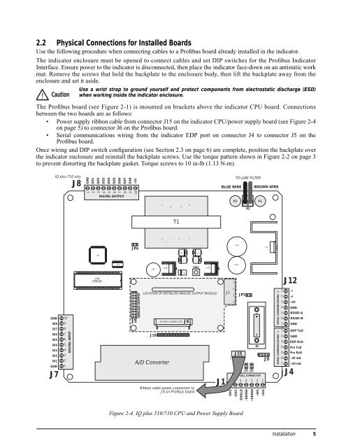
• Power supply ribbon cable from connector J15 on the indicator CPU/power supply board (see Figure 2-4<br />
on page 5) to connector J6 on the Profibus board.<br />
• Serial communications wiring from the indicator E<strong>DP</strong> port on connector J4 to connector J5 on the<br />
Profibus board.<br />
Once wiring and DIP switch configuration (see Section 2.3 on page 6) are complete, position the backplate over<br />
the indicator enclosure and reinstall the backplate screws. Use the torque pattern shown in Figure 2-2 on page 3<br />
to prevent distorting the backplate gasket. Torque screws to 10 in-lb (1.13 N-m).<br />
GND<br />
DI8<br />
DI7<br />
DI6<br />
DI5<br />
DI4<br />
DI3<br />
DI2<br />
DI1<br />
GND<br />
J7<br />
IQ plus 710 only<br />
10<br />
9<br />
8<br />
7<br />
6<br />
5<br />
4<br />
3<br />
2<br />
1<br />
DIGITAL INPUT<br />
J8<br />
GND<br />
1<br />
DO1<br />
DO2<br />
2<br />
3<br />
1<br />
100<br />
25<br />
U22<br />
50 26<br />
U16<br />
EPROM<br />
DO3<br />
DO4<br />
4<br />
5<br />
75<br />
76<br />
51<br />
DO5<br />
DO6<br />
6<br />
7<br />
DIGITAL OUTPUT<br />
U19<br />
DO7<br />
8<br />
DO8<br />
+5V<br />
10<br />
9<br />
JP4<br />
J5<br />
ANALOG OUTPUT<br />
C96<br />
LOCATION OF INSTALLED ANALOG OUTPUT MODULE<br />
1<br />
J10<br />
10 11<br />
U18<br />
9<br />
A/D Converter<br />
12<br />
3<br />
T1<br />
Figure 2-4. IQ plus 510/710 CPU and Power Supply Board<br />
8<br />
+<br />
14<br />
D6<br />
KEYPAD CONNECTOR<br />
7<br />
D5 D4<br />
C95<br />
J6<br />
Ribbon cable power connection to<br />
J6 on Profibus board<br />
15<br />
6<br />
D9<br />
SW1<br />
U17<br />
J1<br />
BLUE WIRE BROWN WIRE<br />
2<br />
J1<br />
3<br />
1<br />
1<br />
4<br />
C104<br />
C100<br />
–EXC<br />
+EXC<br />
TO LINE FILTER<br />
F2 F1<br />
JP3<br />
J15<br />
SHIELD<br />
–SENSE<br />
P2<br />
B1<br />
JP2 JP1<br />
LOAD CELL CONNECTOR<br />
7 6 5 4 3 2 1<br />
+SENSE<br />
–SIG<br />
+SIG<br />
U23<br />
J9<br />
SERIAL COMMUNICATIONS - 2<br />
SERIAL COMMUNICATIONS - 1<br />
1<br />
2<br />
3<br />
4<br />
5<br />
6<br />
7<br />
1<br />
2<br />
3<br />
4<br />
5<br />
6<br />
7<br />
J12<br />
–I<br />
+I<br />
+5V<br />
GND<br />
GND<br />
J4<br />
RS485-A<br />
Installation<br />
RS485-B<br />
E<strong>DP</strong> TxD<br />
GND<br />
E<strong>DP</strong> RxD<br />
Prn TxD<br />
Prn RxD<br />
–20 mA<br />
+20 mA<br />
5


