opel-vauxhall
opel-vauxhall
opel-vauxhall

Create successful ePaper yourself
Turn your PDF publications into a flip-book with our unique Google optimized e-Paper software.
Engine management<br />
General information<br />
0 Refer to the front of this manual for general test conditions,<br />
terminology, detailed descriptions of wiring faults and a<br />
general trouble shooter for electrical and mechanical faults.<br />
0 Trouble codes are displayed by the malfunction indicator<br />
lamp (MIL).<br />
The ECM fault memory can also be checked using<br />
diagnostic equipment connected to the data link connector<br />
(DLC).<br />
Accessing<br />
Ensure ignition switched OFF.<br />
Bridge data link connector (DLC) terminals 6 and earth O.<br />
NOTE: Models without a terminal in position 6 of the 16-pin DLC<br />
do not display trouble codes using the MIL.<br />
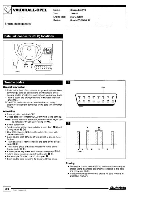
Switch ignition ON.<br />
Trouble codes will be displayed after a short flash [A] and<br />
a long pause rn [B].<br />
Count MIL flashes. Note trouble codes. Compare with<br />
trouble code table.<br />
Each trouble code consists of two groups of one or more<br />
flashes.<br />
The first group of flashes indicate the 'tens' of the trouble<br />
code [C].<br />
The second group of flashes indicate the 'units' of the<br />
trouble code rn [Dl.<br />
A short pause separates each trouble code group rn [E].<br />
A long pause separates each trouble code rn [Fl.<br />
For example: Trouble code 12 displayed rn.<br />
Each trouble code including 12 displayed three times.<br />
Year: 1994-00 I<br />
Engine code: 25DT, X25DT<br />
System: Bosch EDClMSA 11<br />
Erasing<br />
The engine control module (ECM) fault memory can only be<br />
erased using diagnostic equipment connected to the data<br />
link connector (DLC).<br />
Repeat checking procedure to ensure no data remains in<br />
ECM fault memory.