DVD-18C Soldering Terminals - IPC
DVD-18C Soldering Terminals - IPC
DVD-18C Soldering Terminals - IPC
You also want an ePaper? Increase the reach of your titles
YUMPU automatically turns print PDFs into web optimized ePapers that Google loves.
Humor Opening<br />
<strong>DVD</strong>-<strong>18C</strong> Transcript<br />
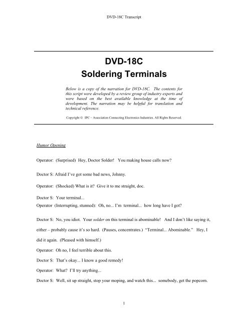
<strong>DVD</strong>-<strong>18C</strong><br />
<strong>Soldering</strong> <strong>Terminals</strong><br />
Below is a copy of the narration for <strong>DVD</strong>-<strong>18C</strong>. The contents for<br />
this script were developed by a review group of industry experts and<br />
were based on the best available knowledge at the time of<br />
development. The narration may be helpful for translation and<br />
technical reference.<br />
Copyright © <strong>IPC</strong> – Association Connecting Electronics Industries. All Rights Reserved.<br />
Operator: (Surprised) Hey, Doctor Solder! You making house calls now?<br />
Doctor S: Afraid I’ve got some bad news, Johnny.<br />
Operator: (Shocked) What is it? Give it to me straight, doc.<br />
Doctor S: Your terminal...<br />
Operator (Interrupting, stunned): Oh, no... I’m terminal... how long have I got?<br />
Doctor S: No, you idiot. Your solder on this terminal is abominable! And I don’t like saying it,<br />
either – probably cause it’s so hard. (Pauses, concentrates.) “Terminal... Abominable.” Hey, I<br />
did it again. (Pleased with himself.)<br />
Operator: Oh no, I feel terrible about this.<br />
Doctor S: That’s okay... I know a good remedy!<br />
Operator: What? I’ll try anything...<br />
Doctor S: Well, sit up straight, stop your moping, and watch this... somebody, get the popcorn.<br />
1
Introduction<br />
<strong>DVD</strong>-<strong>18C</strong> Transcript<br />
This video will demonstrate the techniques for hand soldering wires to a variety of terminals. For<br />
our discussion, a terminal is a metallic connection device that is used to terminate a discrete wire,<br />
or wires. The terminal provides both a mechanical and an electrical connection.<br />
There are several different types of terminals – each requiring specific hand soldering techniques.<br />
We'll be examining turret terminals, cup terminals, bifurcated terminals, hook terminals and<br />
pierced terminals. For an overview of the tools and materials required for basic hand soldering of<br />
through hole components to printed circuit boards – as well as safety and handling considerations,<br />
refer to <strong>IPC</strong> videos <strong>DVD</strong>-42C for tin lead soldering and <strong>DVD</strong>-43C for lead free soldering.<br />
A hand soldering iron with interchangeable tips will be used for soldering terminals. There are<br />
conical tips and chisel tips. Conical tips are round and chisel tips are flat. We'll be using chisel<br />
tips because they have a flat edge. A chisel tip with a flat surface has a much greater contact area<br />
than a conical tip – and therefore transfers heat more efficiently.<br />
The first step is to tin the tip of the iron. Tinning will reduce the formation of oxides on the<br />
soldering iron tip. Oxidation acts as a barrier or an insulator – meaning it slows down the<br />
transfer of heat. It may also prevent wetting of the surfaces with fresh solder. Tinning the tip<br />
with solder also results in faster heat transfer.<br />
The insulated wire also needs to be stripped and tinned prior to attachment to the terminal. There<br />
are many ways to strip the insulated wire. Some methods are unacceptable because of possible<br />
damage to the insulation and the wire. The safest method uses the thermal stripper – which melts<br />
or softens the insulation. Use your fingers to twist the insulation slug off in the direction of the<br />
wire lay. Do not use the stripper to pull off the insulation slug as it can potentially damage the<br />
wire. The main disadvantage of thermal strippers is that some insulation, such as PVC, will burn<br />
and release hazardous gasses when melted. If you’re not sure which types of insulation are<br />
appropriate for thermal stripping, be sure to ask your supervisor.<br />
The stripped wire now needs to be tinned. The purpose of tinning is to avoid damage to the<br />
individual strands when the wire is bent – and to improve solderability. To tin the wire, you can<br />
move it across a solder coated iron tip, move a tinned tip over a stationary wire, or dip it in a<br />
solder pot.<br />
Before we begin soldering terminals it’s important to clean the soldering iron tip. This can be<br />
done by wiping the tip on a slightly damp, sulfur free sponge – or dabbing it on a brass pad made<br />
specifically for hand soldering.<br />
Turret <strong>Terminals</strong><br />
We’ll start with the turret terminal. The tinned end of the wire is first formed into a loop since<br />
the wire will need to be wrapped around the terminal. The loop is then cut to fit the terminal.<br />
The wire end should not extend off the base of the terminal by more than one lead diameter.<br />
2
<strong>DVD</strong>-<strong>18C</strong> Transcript<br />
When forming the wire, you should use a tool that does not leave marks or impressions on the<br />
conductor – such as round nose pliers. The loop you make with the wire should curve like a<br />
semi-circle. An angled loop is not acceptable.<br />
Now the wire can be placed in position on the turret terminal. You know you have made a good<br />
loop when it snaps into place and wants to stay on the terminal even without any solder.<br />
There can be different degrees of termination of the wire wraps. For example, 180 degrees is half<br />
way around the terminal and 360 degrees is all the way around, or one complete turn. Your<br />
acceptance requirements may be based on your company’s specification, or <strong>IPC</strong> standards. For<br />
example, <strong>IPC</strong>-A-610 specifies that a wire diameter of 28 AWG or larger – built to class 3<br />
requirements – should wrap 180 to 360 degrees. A 30 AWG wire diameter or smaller – built to<br />
class 3 – should be wrapped more than one complete turn.<br />
During the soldering process nothing – except for the technician’s hands – should move. This<br />
will eliminate the risk of disturbed solder. The terminal should be mounted securely – and the<br />
non-soldered wire end should be held by a third hand tool, or equivalent.<br />
In the case of our turret terminal, if one wire is to be connected, it should be placed on the lower<br />
section of the terminal. It should lay flat against the base so that any mechanical stress will be<br />
transferred to the board rather than tilting the terminal and perhaps damaging the land. Another<br />
benefit of mounting the wire on the base is that the wire actually ends up against a corner between<br />
the base and the post. After creating top and bottom solder fillets, there will be a very strong<br />
mechanical connection. The turret manufacturers loved this idea so much, they gave you two<br />
bases to work with.<br />
With two wires, they should both be brought in from the same side so that the insulations touch.<br />
This will leave a gap between the stripped areas of the wires. The gap makes it easier to inspect<br />
the solder joint, and allows for the two parallel wires to be joined with tie wraps or lacing.<br />
Now let's take a look at the proper technique for soldering turret terminals. The soldering<br />
operation consists of four basic steps. In step 1, the solder wire is placed in contact with the<br />
wrapped wire and the terminal. This is the point of greatest thermal mass and is called the<br />
"contact point." This contact point will help to transfer the heat to both the wire and the terminal<br />
simultaneously. The soldering iron tip is brought into the contact point – melting the solder wire<br />
– thus forming a solder heat bridge. The purpose of the solder heat bridge is to transfer heat<br />
more rapidly to the solder fillet area and to preheat the wire and terminal so they are hot enough<br />
to melt solder.<br />
During step 2, additional solder is applied on the opposite side of the contact point to form the<br />
necessary solder fillet. You will know you made a good heat bridge if the solder melts rapidly<br />
when it contacts the wire or the terminal.<br />
In step 3, the solder wire is removed. In the final step, the iron is withdrawn at the same angle it<br />
was introduced into the joint.<br />
Notice that the iron was inserted at one location, held still to transfer maximum heat, and then<br />
removed. The iron should not be moved up and down – making multiple contacts. It’s<br />
appropriate to think of the soldering iron as a heat source – not a paint brush. Let’s watch the<br />
entire operation once again in real time.<br />
3
<strong>DVD</strong>-<strong>18C</strong> Transcript<br />
Another method of forming a solder heat bridge is to first place the soldering iron tip in contact<br />
with the wire and the terminal – and then add a small amount of solder to the contact point.<br />
Again, additional solder is applied on the opposite side of the contact point to form the necessary<br />
solder fillet.<br />
At this point, we'll remove the flux to inspect the joint. The cleaning requirements are the same<br />
as any other hand solder connections on a circuit board. Some companies use low residue or noclean<br />
fluxes which may not require cleaning. Other fluxes can cause corrosion or contribute to<br />
dendritic growth. These residues will need to be cleaned off. It is important to adhere to the<br />
manufacturer's specification for solder temperature and cleaning requirements. Your company<br />
will supply you with a compatible cleaning solvent and instructions for its use. They will make<br />
the decision whether to clean or not based on customer requirements for reliability or cosmetic<br />
quality.<br />
Once the flux is cleaned, we’re ready to inspect the solder joint. Do you know how to determine<br />
the correct amount of solder? What exactly do you look for when examining a solder joint?<br />
<strong>IPC</strong>-A-610, J-STD-001 and <strong>IPC</strong>-A-620 all provide acceptance criteria for soldering terminals.<br />
Check that the solder is feathered out smoothly – showing good wetting action over the wire and<br />
the terminal. Wetting is the adhesion of a smooth, unbroken film of solder onto a base metal.<br />
The outline of the wire should be visible under a thin film of solder. This connection location is<br />
called a fillet. On a proper solder joint, the solder fillet is slightly concave, or curved inward. A<br />
concave fillet that tapers to a feathered edge not only looks good, but also reassures us that the<br />
solder bonded to the two surfaces we were trying to join.<br />
When there is insufficient solder, the joint may not have acceptable mechanical strength. When<br />
there is excessive solder, the fillet will be convex and the outline of the wire will be buried in the<br />
mound of solder. This is undesirable because the excess solder can hide defects in the<br />
connection.<br />
It is important to solder so that the joint can be visually inspected. <strong>Soldering</strong> for inspectability<br />
means you're always able to see the outline of the wire in the joint. When excess solder is<br />
evident, the outline of the wire will not be visible.<br />
Cup <strong>Terminals</strong><br />
The next type of terminal we’ll discuss is the cup terminal. The cup part is a hollow cylinder.<br />
The wire will be inserted into the cup and then soldered. During any soldering process nothing<br />
except the technician’s hands should move. This will eliminate the risk of disturbed solder. The<br />
terminal needs to be mounted securely – and the non-soldered wire end should be held by a third-<br />
hand tool, or equivalent.<br />
The wire size must be matched to the terminal. Never modify the wire or the terminal to make the<br />
wire fit. Several smaller wires may be placed into a single cup – as long as the wires do not<br />
exceed the diameter of the cup. It is not acceptable to twist multiple wires together before<br />
inserting them. The twisted wires may trap flux inside and may also change the acceptable<br />
diameter of the wires that are inserted.<br />
4
<strong>DVD</strong>-<strong>18C</strong> Transcript<br />
Now let’s examine the steps to properly solder wires in cup terminals. First, insert the pre-tinned<br />
wire into the cup to measure for correct wire length and insulation clearance. For minimum<br />
insulation clearance, the insulation may contact the top of the cup, but not interfere with the<br />
solder wetting to the inside of the cup terminal. Maximum insulation clearance should be less<br />
than two wire insulation diameters, or 1.5 millimeters whichever is larger. As you can see, the<br />
insulation clearance in this example is excessive and should be corrected before we solder this<br />
connection.<br />
Now, we’ll place the properly stripped and pre-tinned wire into the cup – and secure the wire<br />
using a third hand tool, or equivalent. The conductor should be fully inserted into the cup –<br />
touching the back wall for its full length. Next, we’ll place a large, clean chisel tip against the<br />
back of the cup to transfer heat into the terminal. Then we’ll insert the solder wire into the cup<br />
opening – against the back wall to form a small fillet between the back wall and the wire.<br />
In the final step, we’ll move the solder wire to the center to avoid touching the left or right edges<br />
–minimizing the chance of spilling over as the cup fills with solder. The solder wire and<br />
soldering iron tip are then removed from the cup at the same time. It’s important to leave<br />
everything still until the solder solidifies.<br />
If excessive solder is used, it will spill down the sides of the cup. If insufficient solder is used, the<br />
solder connection won’t have the required mechanical strength.<br />
At this point, we’ll clean off the flux – if required. Here is what the acceptable solder joint will<br />
look like. The wire is fully in the cup and there is an insulation clearance from the top of the cup<br />
to the insulation of the wire. The solder contains no dips or recesses within it, and hasn't spilled<br />
over and down the sides of the cup. Also, check that there is no buildup of solder on the cup<br />
where the soldering iron made contact. If there is a small quantity of external solder, it should be<br />
a smooth film with no bumps. When the solder volume is correct, the fillets are slightly concave<br />
and show good wetting on all the surfaces. Unlike the other terminals, the outline of the<br />
conductor is not required to be visible inside the cup.<br />
When there is insufficient solder, the connection may not have acceptable mechanical strength.<br />
When excessive solder is used, solder buildup on the outside of the cup may negatively affect the<br />
form, fit, function or reliability.<br />
In situations where the cup terminal is inside a connector, the soldering operation is much more<br />
difficult. The area you'll be working in is considerably smaller and there is the danger of possibly<br />
burning or damaging adjacent wires. In this case, a resistance soldering tool can be useful. This<br />
tool contains a pair of electrodes that can grip the cup and send electrical current through it. The<br />
current will heat up the metal and melt the solder. The manual for the resistance soldering tool<br />
will specify the correct setting based upon the type of terminal you're soldering. The advantage of<br />
this tool is that the electrodes can be positioned before the heat is turned on. That means you<br />
won’t accidentally heat the wrong area and possibly cause damage. The cup containing the solder<br />
is gripped with firm pressure and a foot switch is depressed to start the heat.<br />
Insert the wire – press the foot pedal – and feed in the solder. Then release the foot switch. After<br />
solder solidification, remove the electrodes. The foot switch should always be released before the<br />
electrodes are removed to prevent arcing. Electrical arcing could damage the plating on the<br />
terminal.<br />
5
Bifurcated <strong>Terminals</strong><br />
<strong>DVD</strong>-<strong>18C</strong> Transcript<br />
Now let's take a look at bifurcated, or forked terminals. On these terminals, the wires can enter<br />
from the side, the top, or the bottom. Side entry is commonly used when one or more wires are<br />
connected. The recommended minimum wrap on a bifurcated terminal is 90 degrees. 180 degrees<br />
is used when additional mechanical strength is desired, and when there is sufficient clearance<br />
between adjacent terminals. When two or more wires are required, they should be wrapped to<br />
alternating posts.<br />
Let's watch the soldering operation for a side route installation of one wire. The pre-tinned wire<br />
is laid across the terminals to determine the proper insulation clearance. A 180 degree wrap is<br />
made using a pliers that won’t cause damage to the wire. The wire is now positioned and<br />
trimmed so that it doesn't protrude more than one conductor diameter beyond the edge of the<br />
terminal. We do this to make sure the conductor doesn’t violate electrical clearance and cause a<br />
short circuit. The wire should be mounted at the bottom of the slot – between the terminal posts.<br />
Now, place the solder wire in contact with the terminal base and the wrapped wire.<br />
Next, a solder heat bridge is made. Remember, the purpose of the heat bridge is to transfer the<br />
heat more quickly to the connection and to preheat both the wire and terminal so they are hot<br />
enough to melt the solder. Then the solder is touched to the other side to form a proper solder<br />
fillet. After the right amount of solder is melted, remove the solder wire – followed by the iron.<br />
Let’s watch these steps once again – in real time.<br />
The joint can now be cleaned – if required. The acceptable joint will have a concave fillet<br />
between the wire and the terminal. It should be smooth, clean, and display evidence of wetting. It<br />
is recommended that the wire should be in contact with all three terminal post surfaces. Here’s<br />
another joint that has insufficient solder and may not have acceptable mechanical strength. Also,<br />
notice that the wire is extending beyond the edge of the terminal more than one lead diameter –<br />
which is not acceptable. This joint has excessive solder. The fillet bulges out and the outline of<br />
the wire is covered by the excess solder.<br />
In addition to side entry, wires may also enter from the top or bottom. For top entry of bifurcated<br />
terminals, the tinned wire may be bent to double thickness – thereby contacting more surfaces for<br />
a stronger connection. Once properly inserted, the wire is soldered. If the wire is too large for<br />
double thickness, a filler wire is cut to length and added to fill the space. For bottom entry, the<br />
wire is bent a minimum of 90 degrees from where it comes up through the hole. The wire should<br />
then be trimmed so it doesn't protrude more than one wire diameter beyond the edge of the<br />
terminal. Make sure the wire insulation does not enter the hollow terminal.<br />
Hook <strong>Terminals</strong><br />
Next, we’ll look at hook terminals. Hook terminals are found primarily on hermetically sealed<br />
relays. The wire wrap should be at least 180 degrees. Numerous tools can be used to make the<br />
wrap for hook terminals as long as they don’t nick, scrape or leave impressions on the conductor.<br />
One example that we’ll use here is round nosed pliers.<br />
6
<strong>DVD</strong>-<strong>18C</strong> Transcript<br />
Now let's examine how hook terminals are soldered. Once the wire is pre-tinned, formed, and<br />
attached to the terminal – and held in place with a third hand tool – the solder wire is placed in<br />
contact with the terminal and the wrapped wire. Next, a solder heat bridge is formed. Then the<br />
solder is moved to the opposite side of the fillet area. After the solder flows over the wire to form<br />
the proper fillet, the solder wire is removed. Then the iron is withdrawn at the same angle it was<br />
introduced to the joint. Last, we clean off all flux – if required.<br />
The acceptable solder joint will have the same characteristics we've seen so far – slightly concave<br />
fillets and evidence of good wetting. Here are two unacceptable solder joints – with insufficient<br />
solder and excessive solder.<br />
Pierced <strong>Terminals</strong><br />
The last terminal we'll be soldering is the pierced terminal. Pierced terminals have a hole in the<br />
middle. The hole may be a circular, oval or square. Wire can enter from either side, or from the<br />
top. The pre-tinned wire should be mounted through the hole, then wrapped and positioned to<br />
contact both the flat sides of the terminal – and held with a third hand tool.<br />
Let's watch the proper soldering operation for pierced terminals. Notice that it's the same basic<br />
procedure we've seen for many of the terminals. Remember the four basic steps of the soldering<br />
operation.<br />
The solder wire is placed at the point of greatest thermal mass – in contact with the terminal and<br />
the wrapped wire. Additional solder is then applied on the opposite side of the contact point to<br />
form the necessary solder fillet. The solder wire is removed when a sufficient amount of solder<br />
has been added to the joint. Finally, the iron is withdrawn at the same angle it was introduced to<br />
the joint. Then the flux is cleaned off – if required.<br />
The target joint will have a concave fillet between the wire and the terminal. It is not necessary to<br />
fill the hole of a pierced terminal with solder. The solder fillet only needs to be between the wire<br />
and the flat surfaces of the terminal. It should be smooth, clean, and display evidence of wetting.<br />
When there is insufficient solder, the joint may not have acceptable mechanical strength. When<br />
there is excessive solder, the fillet will be convex and the outline of the wire will be buried in the<br />
mound of solder. This is undesirable because the excess solder can hide defects in the<br />
connection.<br />
Summary<br />
As you've seen, there are many different types of terminals and wire positioning arrangements –<br />
but the same soldering procedures apply to all. We’ve shown the methods for soldering turret<br />
terminals...cup terminals...bifurcated terminals...hook terminals...and pierced terminals.<br />
<strong>Terminals</strong> are part of our everyday lives. When we turn on our electronic products, we are<br />
relying on someone’s careful assembly of wires to terminals somewhere inside the chassis. It’s<br />
important to always do our best quality work.<br />
7
<strong>DVD</strong>-<strong>18C</strong> Transcript<br />
And take it from Dr. Solder -- you never know whose life and livelihood may be depending on<br />
us. Now, make two solder joints and call me in the morning.<br />
8


