OWNER'S MANUAL - Rick English - Swimming Pool Consultant
OWNER'S MANUAL - Rick English - Swimming Pool Consultant
OWNER'S MANUAL - Rick English - Swimming Pool Consultant

Create successful ePaper yourself
Turn your PDF publications into a flip-book with our unique Google optimized e-Paper software.
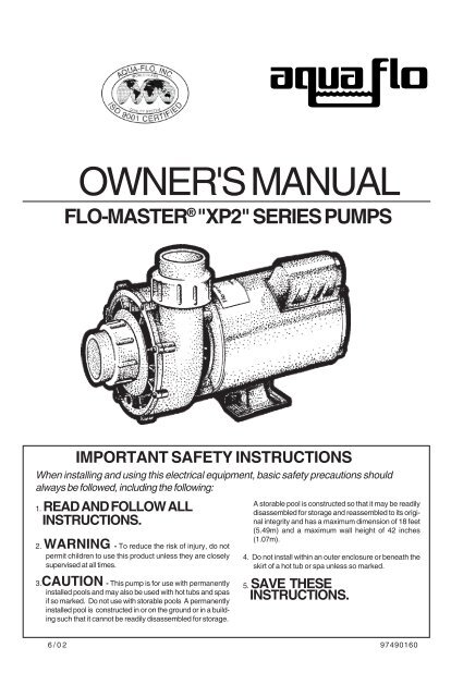
<strong>OWNER'S</strong> <strong>MANUAL</strong><br />
FLO-MASTER ® "XP2" SERIES PUMPS<br />
IMPORTANT SAFETY INSTRUCTIONS<br />
When installing and using this electrical equipment, basic safety precautions should<br />
always be followed, including the following:<br />
1. READ AND FOLLOW ALL<br />
INSTRUCTIONS.<br />
2. WARNING - To reduce the risk of injury, do not<br />
permit children to use this product unless they are closely<br />
supervised at all times.<br />
3.CAUTION - This pump is for use with permanently<br />
installed pools and may also be used with hot tubs and spas<br />
if so marked. Do not use with storable pools A permanently<br />
installed pool is constructed in or on the ground or in a building<br />
such that it cannot be readily disassembled for storage.<br />
A storable pool is constructed so that it may be readily<br />
disassembled for storage and reassembled to its original<br />
integrity and has a maximum dimension of 18 feet<br />
(5.49m) and a maximum wall height of 42 inches<br />
(1.07m).<br />
4. Do not install within an outer enclosure or beneath the<br />
skirt of a hot tub or spa unless so marked.<br />
5. SAVE THESE<br />
INSTRUCTIONS.<br />
6/02 97490160
INSTALLATION & OPERATING INSTRUCTIONS<br />
GENERAL<br />
Your AQUA-FLO pump has been quality built and<br />
engineered to give maximum efficiency under normal water<br />
pumping conditions. Consult the manufacturer for any other<br />
applications.<br />
LOCATION OF PUMP<br />
For best pump performance, locate the system as<br />
close to the water source as possible. Provide adequate<br />
access around the pump for inspection and maintenance.<br />
MODELS LESS TRAP<br />
This model was designed for below water level<br />
(flooded suction) applications. Make sure the pump is installed<br />
at a level that will allow the pump casing (volute) to completely<br />
fill with water.<br />
Two quick disconnect compressions fittings are<br />
included with your pump for ease of installation and<br />
maintenance. Make sure the fittings are correctly aligned with<br />
pump connections to allow the O-ring to make the proper seal.<br />
Hand tighten only. Do not use a wrench to tighten fittings.<br />
MODELS WITH TRAP<br />
Avoid excessive tightening of pipe or fittings in any<br />
areas where threaded connections are used.<br />
For NPT threaded connections, use Quick-Seal Teflon<br />
Thread Sealing Compound, Plasto-Joint Stick or any other<br />
sealants formulated specifically for plastics.<br />
STARTING & PRIMING PUMP<br />
Do not run unit dry. Always be certain that the pump<br />
casing and/or trap is filled with water before starting the unit.<br />
Allow a reasonable amount of time for priming. If pump will not<br />
start, or will not prime, see trouble shooting below.<br />
MAINTENANCE<br />
The trap basket should be inspected frequently and<br />
kept clean. To avoid damage to the basket, do not strike when<br />
cleaning. Inspect trap cover O-ring regularly and replace as<br />
necessary.<br />
Keep motor clean. Insure that louvered openings are<br />
free from debris and obstructions. Over a period of time, the<br />
shaft seals may become damaged or worn and must be<br />
replaced.<br />
WINTERIZATION<br />
To prevent damage during freezing conditions, turn off<br />
all electrical power. Drain thoroughly and clean out any debris.<br />
Protect pump and motor from elements by covering or, if<br />
possible, store in a dry, well ventilated room.<br />
WARNING - All electrical wiring of the motor installation must be done by a qualified electrician in accordance with applicable<br />
electrical codes. Before working on any motor be certain that the source of electrical power is off at the main junction box.<br />
BONDING WIRE - Upon installation of the pump, the motor must be bonded with a No. 8 AWG (8.4mm2 ) solid copper conductor<br />
per National Electric Code. The connection should be from the accessible wire connector on the motor to all metal parts of the<br />
swimming pool, spa, or hot tub structure and to all electrical equipment, metal conduit and metal piping within 5 feet (1.5m) of<br />
the inside walls of a swimming pool, spa or hot tub, when the motor is installed within 5 feet of the inside walls of the swimming<br />
pool, spa, or hot tub.<br />
NOTE: For electrical connections, see wiring diagram on motor rating plate.<br />
MOTOR WILL NOT START:<br />
1.) Check Circuit Breakers<br />
2.) Check for incorrect or loose wire connections.<br />
3.) Make sure the correct power supply is being used.<br />
4.) Any on/off switch or pneumatic switch should be in the<br />
"on" mode.<br />
MOTOR OVERHEATING AND CYCLING ON AND OFF:<br />
1.) Check for incorrect or loose wire connections.<br />
2.) Check for low voltage supply (frequently caused by<br />
undersized wire).<br />
3.) Make sure the motor gets a fresh air supply and the<br />
vents are kept unclogged.<br />
MOTOR MAKES HUMMING NOISE BUT WILL NOT<br />
START:<br />
1.) Make sure motor shaft turns free.<br />
2.) Check for jammed impeller or an obstruction in (volute)<br />
casing.<br />
3.) Check for low voltage and undersized wire.<br />
PUMP WILL NOT PRIME:<br />
1.) Make sure pump is installed at the proper level and the<br />
plumbing lines have been correctly installed to allow the<br />
water to enter pump freely.<br />
TROUBLE SHOOTING<br />
2.) Open air control valves to release any possible air lock.<br />
3.) Make sure all suction and discharge lines are clear and<br />
unobstructed and all valves are opened.<br />
4.) Check for air leaks in the suction line.<br />
LOW WATER FLOW:<br />
1.) Check filter pressure gauge, filter may need cleaning.<br />
2.) Check for clogged plumbing lines.<br />
3.) Check for worn or damaged impeller.<br />
4.) Check for low voltage.<br />
WATER LEAKS<br />
1.) Check contamination or damage to shaft rotary seal.<br />
Replace if necessary.<br />
2.) Check compression fitting (union connectors), make<br />
sure they are properly aligned and secured. Hand tighten<br />
only. Do not use tools.<br />
3.) Make sure O-ring is properly seated and not damaged.<br />
NOISES:<br />
1.) Check plumbing vibration-make sure lines are<br />
adequately supported.<br />
2.) Check for cavitation, due to an obstruction in the<br />
suction line; or an undersized suction line.
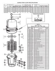
FLO-MASTER ® "XP2" REPLACEMENT PARTS<br />
48-FRAME<br />
REF.<br />
NO.<br />
1<br />
2<br />
3<br />
4<br />
4<br />
4<br />
4<br />
5<br />
6<br />
7<br />
7A<br />
REF.<br />
PART NO. DESCRIPTION PART NO.<br />
NO.<br />
92770705<br />
92500150<br />
91694150<br />
91694200<br />
91694251<br />
91694300<br />
92830070<br />
92200300<br />
91231606<br />
56910090<br />
56-FRAME<br />
REF.<br />
PART NO.<br />
NO.<br />
1<br />
2 92770715<br />
2A 92770725<br />
3 92500150<br />
4 See Chart<br />
Page 4<br />
5 92830070<br />
6 92200300<br />
7 91231606<br />
Motor, 48 Frame<br />
Volute, XP2 series, 48 Frame<br />
Seal, replacement, #200, XP2<br />
Impeller, XP2 Series, 1.5 HP<br />
Impeller, XP2 Series, 2.0 HP<br />
Impeller, XP2 Series, 2.5 HP<br />
Impeller, XP2 Series, 3.0 HP<br />
Wear Ring, Flanged, XP2 Series<br />
O-ring, Volute XP2 Series, #164<br />
Cover, Suction, XP2 Series, 2", Std Drain<br />
Replacement Kit Cover Complete,<br />
2", XP2 Series, Std Drain<br />
DESCRIPTION<br />
Motor, 56 Frame<br />
Volute, XP2 series, 56 Frame, 6.1" Dia.<br />
Volute, XP2 series, 56 Frame, 6.3" Dia.<br />
Seal, replacement, #200, XP2<br />
Impeller<br />
Wear Ring, Flanged, XP2 Series<br />
O-ring, Volute XP2 Series, #164<br />
Cover, Suction, XP2 Series, 2", Std Drain<br />
8<br />
9<br />
10<br />
11<br />
12<br />
13<br />
14<br />
✱<br />
✱<br />
✱<br />
✱<br />
REF.<br />
NO.<br />
7A<br />
8<br />
9<br />
10<br />
11<br />
12<br />
13<br />
14<br />
✱<br />
92200060<br />
92290070<br />
99730050<br />
92200210<br />
91431200<br />
91431150<br />
52202000<br />
91041609-000<br />
91041610-000<br />
91041611-100<br />
91041612-100<br />
PART NO.<br />
56910090<br />
92200060<br />
92290070<br />
99730050<br />
92200210<br />
91431200<br />
91431150<br />
52202000<br />
See Chart Below<br />
DESCRIPTION<br />
O-ring, Drain Plug, #111, XP2<br />
Plug, Drain ¼ - 18 NPSM, Wing, XP2 Series<br />
Screw, 8-32 x 5/8" Long, XP2<br />
O-ring, #230<br />
Fitting, Tail Piece, 2"<br />
Fitting, Union Nut, 2"<br />
Fitting, Compression Complete, 2" x 2"<br />
1.5 HP Wet End, 2", XP2, Std. Drain<br />
2.0 HP Wet End, 2", XP2, Std. Drain<br />
2.5 HP Wet End, 2", XP2, Std. Drain<br />
3.0 HP Wet End, 2", XP2, Std. Drain<br />
DESCRIPTION<br />
Replacement Kit Cover Complete,<br />
2", XP2 Series, Std Drain<br />
O-ring, Drain Plug, #111, XP2<br />
Plug, Drain ¼ - 18 NPSM, Wing, XP2 Series<br />
Screw, 8-32 x 5/8" Long, XP2<br />
O-ring, #230<br />
Fitting, Tail Piece, 2"<br />
Fitting, Union Nut, 2"<br />
Fitting, Compression Complete, 2" x 2"<br />
Assembly, Wet End, Complete<br />
✱ Includes Ref. Items #2-10
FLO-MASTER ® "XP2" REPLACEMENT PARTS<br />
Flo-Master "XP2" 56 Frame Impeller & Wet End Guidelines<br />
To order a replacement part, ALWAYS use the part number molded on the impeller being replaced. If the<br />
part number of the part to be replaced is not known, use the chart below as a guideline for replacement of<br />
impellers & wet ends.<br />
XP2 Pump With 56 Frame<br />
First 5 digits of Pump Model number<br />
Single Speed<br />
Two Speed<br />
Impeller #<br />
Wet<br />
End<br />
#<br />
06015xxx,<br />
06515xxx<br />
07015xxx,<br />
07515xxx<br />
06020xxx,<br />
06520xxx<br />
07020xxx,<br />
07520xxx<br />
06025xxx,<br />
06525xxx<br />
07025xxx,<br />
07525xxx<br />
06030xxx,<br />
06530xxx<br />
07030xxx,<br />
07530xxx<br />
First 5 digits of Pump Model number<br />
06115xxx,<br />
06615xxx<br />
07115xxx,<br />
07615xxx<br />
06120xxx,<br />
06620xxx<br />
07120xxx,<br />
07620xxx<br />
06125xxx,<br />
06625xxx<br />
07125xxx,<br />
07625xxx<br />
06130xxx,<br />
06630xxx<br />
07130xxx,<br />
07630xxx<br />
91694150 91041621-000<br />
91694200 91041622-000<br />
91694251 91041623-100<br />
91694300 91041624-000<br />
Single Speed<br />
Two Speed<br />
Impeller # Wet<br />
End<br />
#<br />
07210xxx, 07710xxx<br />
07310xxx, 07810xxx<br />
91694110 91041630-000<br />
07215xxx, 07715xxx<br />
07315xxx, 07815xxx<br />
91694150 91041631-000<br />
07220xxx, 07720xxx<br />
07320xxx, 07820xxx<br />
91694200 91041632-000<br />
07225xxx, 07725xxx<br />
07325xxx, 07825xxx<br />
91694251 91041633-100<br />
07230xxx, 07730xxx<br />
07330xxx, 07830xxx<br />
91694300 91041634-000<br />
07240xxx, 07740xxx<br />
07340xxx, 07840xxx<br />
91694400 91041635-000<br />
Consult Aqua-Flo Customer Service Dept. @ (909) 591-7453 for the following:<br />
1. To Order FMXP Replacement Parts.<br />
2. For part numbers not shown in table or unsure of the number.<br />
It is necessary to have the pump model number available to receive service<br />
information.<br />
Note: For FMXP Models - Volute (#2), O-ring, Volute (#6) and Cover, Suction (#7, 7A) are not interchangeable with XP2 parts.<br />
All other parts are interchangeable
ASSEMBLY INSTRUCTIONS<br />
(Including Impeller & Seal Replacement)<br />
WARNING: ALWAYS DISCONNECT THE ELECTRICAL POWER FROM THE PUMP MOTOR BEFORE PERFORMING ANY WORK ON<br />
THE PUMP UNIT.<br />
To Disassemble Pump<br />
CAUTION: DRAIN THE WATER FROM THE PLUMBING LINES BEFORE DISCONNECTING THE PUMP. ALWAYS PROTECT THE<br />
MOTOR FROM POSSIBLE WATER DAMAGE.<br />
Removing the Suction Cover<br />
1. Remove the cover by removing the screws securing the cover to the volute (casing). These screws are located at<br />
the perimeter of the cover.<br />
2. Note the orientation of the loose wear ring on the impeller hub before disassembling.<br />
Removing the Impeller<br />
1. Hold the motor shaft from rotating as follows: At the rear of the motor, insert a wide blade screwdriver in the shaft<br />
end slot, or use a needle nose ‘vise grip’ or pliers to hold the shaft between the motor face and impeller sleeve<br />
opening. Caution: Do not grip impeller sleeve.<br />
2. Turn the impeller counter clockwise until it is completely free from the motor shaft thread.<br />
Removing the Volute (Casing) from the Motor<br />
1. Unscrew the four (4) bolts located at the rear of the motor. These bolts extend through the entire length of the<br />
motor into the 4 legs of the volute.<br />
2. When the 4 legs of the volute are completely disengaged from all the bolts, slide the volute off of the motor shaft.<br />
Inspecting the Seal<br />
1. Carefully examine the surfaces of the carbon disk (black rigid part of seal rotating assembly, mounted on<br />
impeller) and the white ceramic ring (at seal stationary assembly on volute) for edge chipping, surface scratches,<br />
or uneven wear. The surfaces should be smooth and free from damage.<br />
2. The rest of the seal assembly should be free from cracks and should fit snugly with their respective mating parts.<br />
3. Use alcohol wipes or isopropyl alcohol with clean ‘lint free’ soft cloth to clean the carbon disk and the ceramic<br />
ring surface if reusing the same assemblies.<br />
NOTE: IT IS ADVISABLE TO REPLACE THE COMPLETE SEAL ASSEMBLY (BOH THE CERAMIC AND CARBON SIDES) EVERY TIME<br />
THE PUMP IS DISASSEMBLED.<br />
Removing the Seal Assemblies<br />
1. Remove the seal rotating assembly from the impeller by carefully sliding it off of the impeller sleeve.<br />
2. Remove the ceramic ring and rubber boot by knocking it out and/or prying it loose through the rear opening of the<br />
volute. Be sure not to scratch or damage the ceramic surface if you are reusing this part. Caution must be used<br />
so as not to damage the volute wall.<br />
Installing the New Seal Assemblies<br />
1. Seal Rotating Assembly: Carbon Disk, Spring, Steel Collar, Rubber Ring<br />
a. Before installing the seal rotating assembly, apply water to the shaft sleeve.<br />
b. Grasp the assembly with the carbon disk facing outward. Insert the impeller sleeve through the steel collar<br />
side. Using a twisting motion, push until the steel collar touches the base of the sleeve.<br />
2. Seal Stationary Assembly: Ceramic Ring, Rubber Boot<br />
a. Before installing the stationary assembly, apply water to the rubber boot’s ribbings.<br />
b. Being careful not to damage the ceramic ring surface, press the seal assembly squarely into the seal cavity of<br />
the volute.<br />
Reinstalling the Volute (Casing) to the Motor<br />
1. Align the four bolts located at the rear of the motor, with the 4 volute legs. These bolts extend through the entire<br />
length of the motor, into the legs of the volute.<br />
2. Pre-tighten the four bolts. Make sure that the motor shaft is accurately located in the center of (not touching) the<br />
ceramic ring.<br />
3. When the motor shaft is properly located, tighten the four bolts to secure the volute in place.<br />
(continued)<br />
Reinstalling the Impeller<br />
1. Hold the motor shaft from rotating as follows: At the rear of the motor, insert a wide blade screwdriver in the shaft<br />
end slot, or use a needle nose ‘vise grip’ or pliers to hold the shaft between the motor face and impeller sleeve<br />
opening.<br />
2. Thread the impeller clockwise over the motor shaft. Hand tighten only. Make sure the seal carbon disk is in<br />
contact with ceramic ring. Caution: Do not grip impeller sleeve.
3. Reinstall the wear ring over the impeller hub in correct orientation.<br />
Reinstalling the Suction Cover<br />
1. Inspect the o-ring for damage. Replace if necessary.<br />
2. Properly install the o-ring on the cover before mounting the cover to the volute.<br />
3. Cover can be mounted to the volute in one orientation only. An ‘aligning’ feature is built-in with each part, to<br />
ensure proper mounting. When properly aligned, the cover should slide in easily.<br />
4. Secure the cover to the volute with screws. Tighten all screws alternately (crisscrossing the cover) to achieve<br />
proper o-ring compression and cover seating.<br />
5. Rotate the impeller by hand to make sure that it is rotating freely, without any interference.<br />
Reconnecting the Pump Unit<br />
1. Clean the seals, gaskets, or o-rings of the plumbing connectors. Replace if cracked, worn, or damaged.<br />
2. Reconnect the plumbing lines to the pump. Hand tighten only.<br />
3. Be sure that the pump unit is secured properly to the platform or base, if applicable. Tighten the bolts if<br />
necessary.<br />
4. Reconnect the power supply. Be sure that all wires are properly and securely connected.<br />
CAUTION: BEFORE TURNING THE POWER ON, BE SURE THAT: 1) THERE IS AN ADEQUATE AMOUNT OF WATER IN THE<br />
SYSTEM; 2) ALL VALVES ARE OPEN TO ALLOW WATER CIRCULATION; 3) ALL CONNECTORS AND FITTINGS ARE PROPERLY<br />
ALIGNED AND SECURE.<br />
WARRANTS TO:<br />
FLO-MASTER ® "XP" SERIES PUMPS LIMITED WARRANTY<br />
____________________________________________<br />
________________________________________________________________________________________________<br />
the original retail purchaser only, that the products<br />
they manufacture are free from defects in material and/or<br />
workmanship for a period of five years (pump seals warranty<br />
for 30 days) from date of purchase. If within the first two<br />
years, any such products shall prove defective, it shall be<br />
repaired or replaced at AQUA-FLO’S option as follows:<br />
The original retail purchaser shall first contact the<br />
installing dealer, as soon as possible after discovery of the<br />
defect, but in no event later that the expiration date of this<br />
warranty. Or upon notification,<br />
AQUA-FLO, INC.<br />
Customer Service Department<br />
P.O. Box 2526, Chino, CA 91708<br />
will advise the consumer of the address to which<br />
the defective item may be shipped, together with the model<br />
number, serial number and date of purchase of item claimed<br />
to be defective. The consumer must pay for all shipping<br />
charges.<br />
If within the years three through five any such<br />
products shall prove defective, the original retail purchaser<br />
shall be entitled to purchase replacement equipment or<br />
components at the following percentage off the current<br />
published list price:<br />
Aqua-Flo, Inc.<br />
Third year 60%<br />
Fourth year 40%<br />
Fifth year 20%<br />
EXCLUSIONS<br />
PUMPS FOR THE LEISURE WATER INDUSTRY<br />
Box 2526 / Chino, CA 91710<br />
Shipping: 5651 Schaefer Ave. / Chino, CA 91710<br />
FAX: 909/627-5660 TEL: 909/591-7453<br />
www.aqua-flo.com<br />
1. This warranty shall not apply to any failures<br />
resulting from negligence, abuse, misuse, misapplication,<br />
improper installation, alteration or modification, chemical<br />
corrosion, or improper maintenance.<br />
2. Any items manufactured by other companies<br />
and used by AQUA-FLO in its products may carry warranties<br />
by the original manufacturers.<br />
3. AQUA-FLO is not liable for incidental or<br />
consequential damages, loss of time, inconvenience,<br />
incidental expenses, labor or material charges in connection<br />
with removal or replacement of the<br />
equipment.<br />
AQUA-FLO is not responsible for any implied<br />
warranties or representations by others and the foregoing<br />
warranty is exclusive and in lieu of all warranties provided<br />
herein.<br />
Some states do not allow the exclusion or limitation<br />
of incidental or consequential damages, so the above<br />
limitation or exclusion may not apply to you.<br />
This warranty gives you specific legal rights and you<br />
may also have other rights, which vary from state to state.