Waterford Systems - Rick English - Swimming Pool Consultant
Waterford Systems - Rick English - Swimming Pool Consultant
Waterford Systems - Rick English - Swimming Pool Consultant

You also want an ePaper? Increase the reach of your titles
YUMPU automatically turns print PDFs into web optimized ePapers that Google loves.
WATERFORD SYSTEMSHIGH RATE SAND FILTER SYSTEMFor Above Ground <strong>Swimming</strong> <strong>Pool</strong>sO W N E R’ SM A N U A L839 0494INSTALLATION, OPERATION & PARTSModels15” Tank 17” Tank 20” Tank3/4 HP JSAL15D-06 JSAL17D-06 JSAL20D-061 HP JSAL15E-06 JSAL17E-06 JSAL20E-061 HP (2-Speed) JSAL17E-09 JSAL20E-091-1/2 HP JSAL20F-06Sta-Rite <strong>Pool</strong>/Spa Group293 Wright Street, Delavan, WI 53115North America: 800-752-0183, FAX 800-582-2217International: 414-728-5551, FAX: 414-728-4461, TELEX: ITT 4970245Union City, TN • Delavan, WI • Mississauga, Ont. • Murrieta, CAThis manual should be furnished to the end userof this system; its use will reduce service calls andchance of injury and will lengthen system life.© 1999, Printed in U.S.A 90000-0355 (Rev. 4/13/99)
HIGH-RATE SAND FILTER SYSTEMTo avoid unneeded service calls, prevent possible injuries, and get the mostout of your filter, READ THIS MANUAL CAREFULLY!The High Rate Sand Filter System:• Is designed to circulate and filter water in above ground swimming pools.• Offers quiet, efficient performance and is durable, reliable.Table of ContentsSafety Instructions..........................................................................................3Specifications/Dimensional Data ...................................................................4General Information ......................................................................................5Installation .................................................................................................5-7Filter Mount/Piping.....................................................................................5Filter Set-up................................................................................................6Loading Sand Media...................................................................................6Valve Installation.....................................................................................6-7Startup/Operation/Backwash .........................................................................7Electrical .......................................................................................................8Maintenance .................................................................................................8Storage/Winterizing .......................................................................................9Mult-Port Valve Service .................................................................................9Valve Removal ............................................................................................10Pump Service...............................................................................................11Troubleshooting Guide ................................................................................12Repair Parts List......................................................................................13-15Warranty .....................................................................................................16IMPORTANT SAFETY INSTRUCTIONSWhen installing and using electrical equipment, basic safety precautions should always be followed,including the following:1. READ AND FOLLOW ALL SAFETY INSTRUCTIONS.2. To reduce the risk of injury, do not permitchildren to use this product unless they are closely supervisedat all times.3. Risk of electrical shock. Connect only toa grounding type receptacle protected by a ground-faultcircuit-interrupter (GFCI). Contact a qualified electricianif you cannot verify that the receptacle is protected by aGFCI.4. Do not bury cord. Locate cord to minimize abuse fromlawn mowers, hedge trimmers, and other equipment.5. To reduce the risk of electrical shock,replace a damaged cord immediately.6. To reduce the risk of electrical shock, donot use an extension cord to connect unit to electricalsupply; provide a properly located outlet.7. This pump is for use with permanentlyinstalled pools and may also be used with hot tubs andspas if so marked. Do not use with storable pools. A permanentlyinstalled pool is constructed in or on theground or in a building such that it cannot be readilydisassembled for storage. A storable pool is constructedso that it may be readily disassembled for storage andreassembled to its original integrity.SAVE THESE INSTRUCTIONS2
READ AND FOLLOW SAFETY INSTRUCTIONS!This is the safety-alert symbol. When you seethis symbol on your valve or in this manual, lookfor one of the following signal words and be alert tothe potential for personal injury.warns about hazards that will cause seriouspersonal injury, death or major property damageif ignored.warns about hazards that can cause seriouspersonal injury, death or major property damageif ignored.warns about hazards that will or cancause minor personal injury or property damage if ignored.The label NOTICE indicates special instructionswhich are important but not related to hazards.Carefully read and follow all safety instructions inthis manual and on system.Keep safety labels in good condition.Replace missing or damaged safety labels.Incorrectly installed or tested equipmentmay fail, causing severe injury orproperty damage. Read and follow instructionsin owner's manual when installing and operatingequipment. Have a trained pool professionalperform all pressure tests.1. Do not connect system to a high pressure or citywater system.2. Use equipment only in a pool or spa installation.3. Trapped air in system can cause explosion. BESURE all air is out of system before operating ortesting equipment.Before pressure testing, make the following safetychecks:• Check all clamps, bolts, lids, and system accessoriesbefore testing.• BE SURE all air is out of system before testing.• Tighten Sta-Rite trap lids to 30 ft. lbs. (4.1 kg-cm)torque for testing.• Water pressure for test must be less than 25 PSI (172kPa).• Water temperature for test must be less than 95˚ F.(35˚ C).• Limit test to 24 hours. After test, visually check systemto be sure it is ready for operation. Remove traplid and retighten hand tight only.NOTICE: These parameters apply to Sta-Rite equipmentonly. For non-Sta-Rite equipment, consult manufacturer.WHEN USING SYSTEM:Hazardous Pressure!Can cause tankexplosion.Do not test withcompressed airor operate aboverated pressure.WHEN USING SYSTEM:Hazardous suction.Can trap or tearhair or body parts,causing severe injuryor death.Do not block pumpsuction or pool maindrain.BEFORE WORKINGON PUMP OR MOTOR:Hazardous voltage.Can shock, burn,or cause death.Unplug pump motor.3
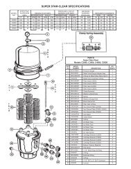
TABLE I - OUTLINE DIMENSIONS IN INCHES (mm)Filter Model A B C D E15”(406mm) Filters 24 (610) 30-7/8 (784) 15-3/4 (400) 21-11/16 (551) 26-1/16 (662)17”(457mm) Filters 26-9/16 (675) 33-5/16 (846) 17-3/4 (451) 24-1/4 (616) 27-1/16 (692)20” (508mm) Filters 28-11/16 (729) 34-7/16 (875) 20-3/4 (527) 26-3/8 (670) 28-9/16 (725)TABLE ll - FILTER SPECIFICATIONS AND OPERATING INFORMATIONFILTER MODEL: 15” 17” 20”(JSAL15 Series) (JSAL17 Series) (JSAL20 Series)Effective Filter Area 1.26 Ft. 2 (.117M 2 ) 1.57 Ft. 2 (.223M 2 ) 2.18 Ft. 2 (.203M 2 )Max. Flow Rate 25.2 GPM(95 L/m) 31.5 GPM(123 L/m) 43.6 GPM(165 L/m)Max. Operating Pressure 40 PSI(276 kPa) 40 PSI(276 kPa) 40 PSI(276 kPa)Max. Operating Temperature 95° F(35°C) 95° F(35°C) 95° F(35°C)Turnover in Hours:6 Hours 9,070 Gal.(34 330 liters) 11,340 Gal.(42 922 liters) 15,700 Gal.(59 424 liters)8 Hours 12,100 Gal.(45 799 liters) 15,120 Gal.(57 229 liters) 20,930 Gal.(79 220 liters)10 Hours 15,120 Gal.(57 229 liters) 18,900 Gal.(71 536 liters) 26,160 Gal.(99 016 liters)12 Hours 18,144 Gal.(68 675 liters) 22,680 Gal.(85 844 liters) 31,390 Gal.(118 811 liters)Qty. of Media Required:Cu. Ft. (cm 3 ) 1(28 320cm 3 ) 1.5(42 255cm 3 ) 2(56 923cm 3 )Weight in lbs.(kg) 100(45,4 kg) 150(68 kg) 200(90,7 kg)NOTE: 1 cubic foot (28 320 cm 3 ) of sand weighs approximately 100 lbs. (45,4kg). DO NOT use a finer grade of sand than recommended.RECOMMENDED SAND GRADES:Use only: #20 Silica Sand, Size Range .40-.55mm., Uniformity Coefficient less than 1.75.NOTICE: Use of other sands will reduce filter performance, may damage pump, and will void warranty.Recommended:1. Wedron Silica/Best Sand Co., Sand Grade: Wedron .45-.55mm., Effective Size .46mm, Uniformity Coefficient 1.22.2. U.S. Silica - Silurian Filter Sand, Sand Grade.45-.55 mm., Effective Size .48mm, Uniformity Coefficient 1.18.CTankDia.1-1/2" NPTWaste Outlet(Union Connection)E1-1/2" NPTReturn to <strong>Pool</strong>(Union Connection)2-13/169-1/162-5/161-1/2" NPTSuctionConnectionABD(To TankFlange)Drain11-1/411 1278 0994237Figure 1: Dimensions1279 09944
GENERAL INFORMATION• Clean a new pool as well as possible before fillingpool and operating filter. Excess dirt and large particlesof foreign matter in the system can cause serious damageto the filter and pump.NEVER test this filter with compressed air.Do not operate filter at water temperatures above95°F (35°C).NEVER operate this filter system at more than 40pounds per square inch (40 PSI/276kPa) pressure!Plug system into electrically isolated, Ground FaultCircuit Interrupter protected circuit ONLY!• Clean a new pool as well as possible before fillingpool and operating filter. Excess dirt and large particlesof foreign matter in the system can cause serious damageto the filter and pump.• Keep pool water pH at recommended level (7.2 to 7.6)to avoid irritation to eyes and skin.• The Hi-Rate Sand Filter System is designed for usewith above ground swimming pools only.• Use only #20 Silica sand with a screen mesh of .45 to.55mm. Use of other sands will reduce filter performance.To reduce risk of electric shock, installpump at least 10 feet from the inside wall of the pool.Do not use an extension cord.INSTALLATIONTrap to Pump Assembly:Using four 5/16” cap screws, flat washers and lockwashers,mount trap to pump body; be sure to install gasket betweentrap and pump body. Tighten cap screws to 80 inchlbs(92 cm-kg) torque; do not overtighten.Filter Mount Must:• Provide weather and freezing protection.• Provide space and lighting for easy access for routinemaintenance. (See Table I and Figure 1, Page 4, forspace requirements.)• Be on a reasonably level surface and provide adequatedrainage.• Be as close to pool as possible to reduce line loss frompipe friction.• Be solid – level– rigid – vibration free.• Be installed so that trap suction inlet is below poolwater level at all times. This allows pump to prime.• Have adequate ventilation to prevent motor overheating.Piping:• Use teflon tape or Plasto-Joint Stik 1 on all male connectionsof plastic pipe and fittings except unions. DONOT use pipe compounds on plastic pipe; it willcause the pipe to crack. Do not use sealant or tape onunions – assemble them dry and hand tight.• Do not damage union sealing surfaces and “O” Rings.• Support pipe independently to prevent strains on filterand valve.• Use 1-1/2 or 2” pipe to reduce pressure losses asmuch as possible. If flex hose is used, use the typewith smooth internal walls.• Fittings restrict flow; for best efficiency use fewest possiblefittings.• Keep piping tight and free of leaks: pump suction lineleaks may cause trapped air in filter tank or loss ofprime at pump; pump discharge line leaks may showup as dampness or jets of water.• When unions are provided, use as follows for leak freeconnections:1. O-Ring and sealing surfaces must be clean.2. Assemble hand tight only (no wrenches).3. No pipe compound or teflon tape on unions.Valves:• For servicing filter system and for cleaning pump trap,install ball or gate valvesA. Between pump trap and pool skimmer, andB. Between selector valve and return pipe to pool.• A check valve installed between filter and heater willprevent hot water from backing up into filter and deforminginternal components.• Use care before assembly not to damage union sealingsurfaces or O Ring.Wastewater:• Be sure all provisions for waste water disposal meetapplicable local, state or national codes. 100 gallons(379 liters) or more of pool water will be dischargedduring filter backwashing. Do not discharge wherewater will cause flooding or damage.1Lake Chemical Co., Chicago, IL5
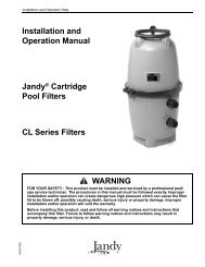
Filter SetupAssembly: See Figures 2 through 5 for filter assembly.Loading Sand Media1. To keep sand out of collector assembly, place plasticsand shield over top of collector tube before pouringsand into filter (See Figure 5).2. To support laterals and prevent lateral breakage duringloading, fill tank about half full of water beforeloading sand.3. Pour sand into filter tank. See “Recommended SandGrades”, Page 4, for correct type and quantity of sandto use.NOTICE: Make sure gasket area on top of tank is freeof sand before installing valve and clamp.4. Before installing valve, double-check that correctquantity of sand has been loaded (see Page 4).5. Remove plastic sand loading shield and keep for futureuse.Valve Installation:See Figures 6, 7, and 81. Install O-Ring on valve flange; make sure O-Ring isclean, dry, and has no nicks, tears, or scrapes.2. Make sure tank and valve flanges are clean and free ofsand; put valve on top of tank. Vertical pipe of collectorassembly inserts into base of valve.3. Install clamp; make sure knob is positioned for easyaccess for filter maintenance. Valve port labeledA. Insert first lateral into socket;twist clockwise 1/4 turnto lock lateral into hub.Lateral is correctly installedwhen slots face down.“PUMP” should point toward pump.4. Tighten clamp knob until clamp ends (under bolt) are1/4” (6mm) apart. Tap around outside of clamp with amallet to help seat clamp.Hazardous pressure. Clamp will nothold unless it is seated properly! DO NOT STARTPUMP until clamp ends are 1/4” (6mm) apart or less.5. If clamp will not pull up to 1/4” (6mm) gap, wait 15-30 minutes and retighten. Tap clamp gently with malletto help seat clamp.6. Connect pipe from pump discharge to valve port labeled“PUMP”; use union half provided. Assembleunion as follows for leakfree operation:A. O-Ring and sealing surfaces must be clean.B. Assemble hand tight only (no wrenches).C. NO pipe compound or teflon tape on unions.7. Complete all plumbing connections (see Page 5 forpiping requirements).A. Pipe from valve RETURN port to pool return.B. Pipe from valve WASTE port to waste.C. Suction piping from pool to trap inlet on pump.D. After alllaterals aresecurely insockets,positionassembly oncenteringboss inbottom oftank.B. Insert assemblyinto top offilter tank.731 0294Figure 4733 0294Figure 2C. Hold assembly upnear top of tank andadd remaininglaterals.732 0294Fill tankabouthalf fullof waterbeforeaddingsand.SAND::::::::::::::::::::::::::::::::::::::::::::::: :::: :::: :::::::: :::: :::::::: :::: :::::::::::: :::: :::: :::::::: :::: :::: :::: :::: :::: :::::::: :::: :::::::: :::::::: :::: :::::::::::: :::::::::::::::::::::::::::::::::::::::::::::::: :::::::: :::::::::::::::::::::::::::::::::::::::::::::::::::: :::: :::::::: :::: :::::::: :::: :::: :::: :::: :::: :::: :::: :::::::: :::: :::::::: :::: ::::Sand Shieldkeeps collectorhub assemblyclean whenloading filter.Figure 3Figure 5734 02946
Aquatools.WATERFORD, WI.53185USAFILTEREAquatools.WATERFORD, WI.53185USAFILTERE8. System is ready for startup.NOTICE: If there are leaks from beneath valve/clamparea, STOP PUMP, release all pressure, remove clampand valve and clean sealing surfaces.Follow directions under “Valve Installation”, Page 6,when reinstalling valve. See Figures 6 and 7.1. Install O-Ringon valve flange.2. Install valve on tank.Tank flange mustbe clean; insertcollector pipeinto bottomof valve.Figure 6Port labeled"PUMP" shouldpoint towardpump.1/4" Max.Install clampand tightenuntil clampends (underbolt) are 1/4"apart.Figure 7BACKWASHRECIRCULATEWASTEBACKWASHRECIRCULATEIf unable toclose gapto 1/4" or less,wait 15-30minutes andretighten.WASTETap aroundclamp whiletightening tohelp seatclamp.736 0294735 0294ELECTRICALHazardous voltage.Can shock, burn,or cause death.Disconnect powerbefore workingon pump or motor.Risk of electrical shock.Plug pump into agrounded, GFCI-protected 115Volt circuit only. Incorrectvoltage can cause fire or seriouslydamage motor and voidswarranty. Protect cord fromwater and physical damage.GFCI tripping indicatesan electrical problem. IfGFCI trips and will not reset,have a qualified electrician inspectand repair electrical system.Risk of electricalshock. Unplug motor beforeservicing or repairing pump ormotor.Wiring:Install a Ground Fault Circuit Interrupter (GFCI) in circuit;it will sense a short-circuit to ground and disconnectpower before it becomes dangerous to pool users.For size of GFCI required and test procedures for GFCI,see manufacturer’s instruction.In case of power outage, check GFCI for tripping (whichwill prevent normal water circulation). Reset if necessary.Match circuit breaker size to Table III below.• Do not modify cord, plug, or receptacle. If an existingcircuit must be used and the receptacle and plug donot match exactly, consult a licensed electrician.• Do not use an extension or drop cord with this system;it could cause a fire hazard or low voltage problems.Wet cords cause shock hazards. Extension cords caneasily become cut or frayed and dangerous whenplaced across yard areas or walkways.Voltage:Voltage at motor must be not more than 10% above orbelow motor nameplate rated voltage or motor mayoverheat, causing overload tripping and reduced componentlife. If voltage is less than 90% or more than 110%of rated voltage when motor is running at full load, consultpower company.Table III–Recommended Fusing Data, 115 Volt 60 Hz Motors.BranchPump Motor Full Load Circuit BreakerModel No. H.P. Amps Rating (Amps)17290-J075 3/4 9.4 1517290-J100 1 13.2 2017290-J150 1-1/2 13.5 2017290-J1002 (2-Speed) 1 – 1/6 11.6/3.3 15NOTICE: Values given are for pump motor only. Do not putany other accessories on this circuit.7
Valve SettingWINTERIZEWASTECLOSEDFILTERBACKWASHRINSERECIRCULATEPurpose/FlowFILTERNormal filtration andvacuuming; water goesthrough filter to pool.Valve SettingWINTERIZECLOSEDWASTEFILTERBACKWASHRINSERECIRCULATEPurpose/FlowBACKWASHReverses flow forcleaning; watergoes through filterto waste.Valve SettingWINTERIZEWASTECLOSEDFILTERBACKWASHWASTEFILTERRINSERINSERECIRCULATEPurpose/FlowWASTELowers pool level ordrains pool; waterbypasses filter,goes to waste.WINTERIZEWASTECLOSEDFILTERBACKWASHRINSERECIRCULATERINSEFor initial startup cleaningand sand bed levelingafter backwash; water goesthrough filter to waste.WINTERIZEWASTECLOSEDFILTERBACKWASHRINSERECIRCULATECLOSEDShuts off all flow tofilter and pool.WASTEFILTERRINSE743 0294WASTEFILTERRINSEWINTERIZECLOSEDWASTEFILTERBACKWASHFigure 8RINSERECIRCULATERECIRCULATECirculates pool water;bypasses filter.737 0294Startup/Operation (See Figure 9)Hazardous suction. Can trap and tear hairor body parts and can cause drowning. Do not blockpump suction. Small children using pool must ALWAYShave close adult supervision.Hazardous pressure. To avoid explosionand possible severe or fatal injury, filter system pressuremust not exceed 40 PSI (276 kPa) under any circumstances.NEVER test this filter system with compressedair; never operate system with water temperature above95° F (35° C).To prevent equipment damage and possibleinjury, turn pump OFF before changing valve position.NOTICE: Do not add chemicals directly into the poolskimmer. Adding undiluted chemicals may damageequipment and void warranty.1. Open system valves and make sure pump is filledwith water.Make sure pool water level is above skimmer or thesuction outlet.2. With pump OFF, set valve to ‘BACKWASH’ position.3. Start pump, circulating water backwards through filterto waste.4. Backwash until water runs clear (3-5 minutes).5. Stop pump; set valve to ‘RINSE’ position.6. Start pump; run pump for one minute.7. Stop pump; set valve to ‘FILTER’ position.8. Filter is now ready for service.9. Record clean starting filter pressure gage reading as areference.10. When pool is first filled, backwash once a day untilpool water is sparkling clear. After that, backwashwhen pressure gage shows 5 to 7 PSI (34.5 to 48kPa) higher than starting pressure.WINTERIZEWASTECLOSEDFILTERBACKWASHRINSERECIRCULATEWINTERIZELeaves all valve portspartially open forwinter storage.738 0294WINTERIZECLOSEDBACKWASHMAINTENANCEGeneral:• Wash outside of filter with a mild detergent and water.Rinse off with hose.NOTICE: DO NOT use solvents to clean filter; solventsmay damage plastic components in system.• Inspect sand bed at least once a year to remove foreignmaterial which has not been backwashed out ofsystem.NOTICE: When the sand bed gets hard and crusty ontop, remove all the old sand and replace it with newsand.Weekly <strong>Pool</strong> Equipment Inspection:1. Check pressure during operation. When pressure is 5to 7 PSI (34.5 to 48 kPa) higher than initial operatingpressure, backwash filter (see instructions under“Startup/Operation”).2. Except during hot weather with heavy swimmer loads,operating filter 6 to 12 hours per day should be sufficient.Carefully monitor water chemical balance andfollow recommendations of your local pool professional.Water MaintenanceRECIRCULATE• Keep water level at least two inches above bottom ofskimmer opening when system is not in operation.Failure to do so can allow air to enter system, causingpump to lose prime and filter to entrap air.• Maintain pH at 7.2 to 7.6 in pool.To prevent damage to system components, keepwater temperature below 95° F. (35° C) at all times.Vacuum <strong>Pool</strong>:1. Fill vacuum hose by submerging in water from oneend to the other.WINTERIZEFigure 9: Valve settings for startup. Stoppump before changing valve position.CLOSEDBACKWASHRECIRCULATEWINTERIZECLOSEDBACKWASHRECIRCULATE8
2. To vacuum, insert hose into skimmer suction manifoldor into vacuum line in pool wall. See instructions providedby pool builder or pool manufacturer. Startpump, making sure it is primed and pumping.3. After vacuuming, clean pump trap to remove accumulateddebris, then check filter pressure gage. If readingis 5 to 7 PSI (34.5 to 48 kPa) higher than initial operatingpressure, backwash filterLower or Drain <strong>Pool</strong>1. Turn pump ‘OFF’; set valve handle to ‘WASTE’.2. Use vacuum cleaner hose and head.3. Start pump; run until pool is lowered to desired level.4. Turn pump ‘OFF’; set valve handle to ‘FILTER’.5. Start pump.STORAGE/WINTERIZING<strong>Pool</strong> chemicals may give off corrosivefumes. Store chemicals away from system in a well ventilatedarea.NOTICE: Allowing water to freeze will damage filter andvoid warranty. If antifreeze is needed, use propylene glycol;it’s plastic compatible and non-toxic. Follow manufacturersinstructions. Do not use ethylene glycol based anti-freeze –it’s toxic and it may damage plastic components.WINTERIZEWASTECLOSEDFILTERBACKWASHRINSERECIRCULATEWINTERIZEWASTECLOSEDFILTERFigure 10: Valve settings to lower pool water level.Stop pump before changing valve position.BACKWASHRINSERECIRCULATEdeterioration over the shutdown period. Have a qualifiedserviceman repair/replace wiring as needed.Inspect and tighten all watertight connections.4. Open all valves in suction and return piping.5. Remove any winterizing plugs in system.6. Drain all winterizing chemicals (if used) from system;flush system.7. Close all drain valves and replace all drain plugs insystem.8. Fill pool with water to proper level (see pool maufacturer’sinstructions).Drain Fitting Installation/RemovalNOTICE: If pool is above height of filter, first closevalves in pump suction and return lines to prevent drainingpool. If there are no shutoff valves installed, disconnectsuction and return lines and raise ends above poolwater level.1. Installation: See Figure 12.2. To Drain Filter:A. Remove drain cap. Lateral tube should remain inplace inside drain opening to prevent sand fromdraining out.B. Open union coupling on backwash port of Multi-Port valve. This will allow air into filter and allowwater to drain from filter tank.C. Replace cap when tank is empty.3. Removing Sand From Filter:A. Remove both drain cap and slotted lateral tube (seeFigure 12). Sand and water will drain from tank.B. To completely flush filter tank of sand, remove topclamp and multiport valve and flush the inside ofthe tank with a hose.C. Thoroughly clean sand from all parts and from tankdrain opening before reassembling drain fitting.WASTEFILTERRINSEAbout 1"WINTERIZECLOSEDBACKWASHRECIRCULATESmallO-RingFigure 11: Valve setting for winter storage.Stop pump before changing valve position.1. Open all system valves. Set multiport valve at ‘WIN-TERIZE’ to allow air passage to all ports.2. Remove drain plug from filter.3. Drain filter tank completely and replace drain cap(Figure 12).4. Cover with plastic or tarpaulin to protect fromweather.5. Protect from freezing.Startup for Winterized Equipment:1. Remove any temporary weather protection placedaround system for shutdown.2. See “Startup”, Page 8, for reactivation of the filter.3. Inspect all electrical wiring to pump for damage orOpen endof lateralSeat smallO-RingLargeO-RingEnd of lateral isflush with end ofdrain fitting 746 0294Figure 12: Drain Fitting Assembly. This assemblyallows water to drain without losing the sand out ofthe filter tank.Make sure all surfaces are clean and free of sand.Don’t cross thread cap; don’t overtighten cap.9
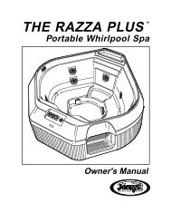
Aquatools.WATERFORD, WI.53185USARINSERECIRCULATEFILTERMULTI-PORT VALVE SERVICEHazardous pressure. Stop pump and releaseall pressure from system before working on filter,valve, or clamp.NOTICE: If Multi-Port valve is below pool water level,close suction and discharge valves before disassembly toprevent draining pool.Handle Replacement:1. Stop pump.2. Place handle in ‘FILTER’ position.3. Remove pin (Key 1, Figure 13) to disconnect handle. Ifit cannot be removed by hand, use a hammer and centerpunch and lightly tap it out.4. Remove handle; replace with a new one. Be sure newhandle is in ‘FILTER’ position.5. Replace pin.Lid and Plug replacement:A. Remove Handle (see ‘Handle Replacement’, above).B. Remove plug:1. Remove all screws and nuts (Key Nos. 2 and 6,Figure 13).2. Remove lid (Key No. 3) by pulling straight up whileholding plug shaft (Key No. 5) down with thumb.C. Inspect Internal Parts:Inspect plug and gasket spring, O-Rings, and internalwashers (Key No. 4). Replace if necessary.D. Reassemble Valve:1. Replace plug gasket and shaft, mounting spring,washers, and O-Ring on plug shaft. Lubricate O-Ring with Amojel.2. Replace lid; match screw holes in lid and body.3. Press down on lid to allow screws to engage nuts;tighten each nut securely.4. Replace top washer (Key No. 1A) and handle, makingsure indexing pin on plug shaft points in samedirection as pointer on handle. Replace handle pin.5. Tighten all lid screws to 55 inch-lbs. (63.4 kg-cm)torque.Valve RemovalHazardous pressure. Stop pump and releaseall pressure from system before working on filter,valve, or clamp.NOTICE: If multi-Port Valve is below pool water level,close suction and discharge valves before disassembly toprevent draining pool.1. Disconnect piping from pump and pool.2. Remove clamp.3. Remove valve from filter top.4. To reinstall valve, follow “Valve installation” instructions,Page 6. BE SURE to follow clamp tightening instructions.623145BACKWASHCLOSEDWINTERIZEWASTE1A744 0294Figure 13: Valve Disassembly10
PUMP SERVICETo protect against possible electric shock,use only identical replacement parts when servicing.System should only be serviced by qualified personnel.Before removing trap cover:1. STOP PUMP before proceeding.2. CLOSE GATE VALVES in suction and discharge pipes.3. RELEASE ALL PRESSURE from pump and piping system.To avoid dangerous or fatal electrical shock hazard,turn OFF power to motor before working onpump or motor.Trap needs no lubrication or regular maintenance beyondreasonable care and periodic cleaning of strainerbasket.If shaft seal is worn or damaged, repair as follows:Pump Disassembly:1.Unplug motor before servicing or repairing pump ormotor.2.Close all valves in suction and discharge piping.3.Remove drain plugs from the bottom of pump andtrap; drain pump completely.4.Disconnect pipe unions (or clamps) on suction anddischarge piping. Remove hold down bolts and withdrawcomplete pump/motor/trap assembly.5.Remove cap screws (Key No. 16, Page 14) from frontplate (Key No. 13). Remove front plate with trap (KeyNo. 20) attached. Remove and inspect O-Ring (KeyNo. 12).6.Remove end cap (Key No. 2) from motor cover (KeyNo. 7).7.Hold motor shaft with 7/16” wrench on flats onmotor shaft; unscrew impeller (Key No. 11).8.Carefully remove rotating half of seal (Key No. 10)from impeller sleeve. Twist as you pull; make sureyou do not damage surface of sleeve where seal bothseats and seals. See Figure 14.9.Remove motor throughbolts (see Figure 15). Removeseal plate (Key No. 9). Tap stationary half of seal outof seal plate (see Figure 16).10. If necessary, disconnect electrical wiring from motorterminal board and remove motor (Key No. 6) frommotor cover (Key No. 7).Pump Assembly:1. Examine seal cup and O-Rings. Replace anything thatshows signs of wear or damage.2. Check the shaft seal (Key No. 10, Page 15) for scoring,scratches, chips, etc., and for any signs of damageto spring or retainer. Replace if any wear ordamage is visible.3.Press stationary half of seal into seal plate (Key No. 9)using finger pressure only (see Figure 17). Make sureseal is firmly and evenly seated.4.Install rotating half of seal on impeller sleeve. Push itonto sleeve until it butts against back of impeller.5.Insert impeller sleeve through center hole in sealplate (Key No. 9). Thread slinger (Key No. 8) over theend of the impeller sleeve.6.If motor has been removed from motor cover, reinstallit now. Set up seal plate (Key No. 9) in front ofmotor cover; hold motor shaft with 7/16” wrench onshaft flats (under cap) and thread impeller throughcenter hole in seal plate onto shaft). Make sure thatslinger is in place on impeller sleeve – not loose onshaft.7.Install motor throughbolts; make sure seal plate buttsfirmly against motor endbell.8.Install front plate (Key No. 13). Tighten cap screws insequence as shown in Figure 18; tighten to 30 inchlbs.(34.5 cm-kg.) torque.9.Reinstall drain plugs; reinstall pump and motor onbase and tighten hold-down bolts.10. Reconnect unions; tighten hand tight only.#2#5 #3#6#4#1 StartHereFigure 18: Pump front Plate Torque Sequence.Figure 14 Figure 15 Figure 16 Figure 1711
TROUBLESHOOTINGGUIDE – PUMPRead and understand safety and operating instructionsin this manual before doing any work onpump.A. Pump does not operate:1. Check GFCI (Ground Fault Circuit Interrupter) forproper operation according to GFCI manufacturer’sinstructions.2. Check for blown fuses, circuit breakers, or disconnectedelectrical wiring.3. Check for sand locked impeller. Disconnect powerto motor; follow pump disassembly instructions,Page 11. Clean out sand from impeller and fromwear ring in front plate. Reassemble according toinstructions, Page 11.4. Consult dealer/installer or service representative.B. Motor runs, but does not pump water or pressurizesystem:1. Check to make sure all valves are open.2. Check skimmer, trap basket, and piping for debrisor obstructions.3. Check pump impeller for obstructions such ashair, leaves, grass, or stones. Follow “PumpDisassembly” instructions, under “Pump Service”on Page 11.4. Consult with dealer/installer or service representative.C. Excessive air in system – pump loses prime:1. Make sure water level in skimmer is at least 2”above bottom of skimmer throat with system notoperating.2. Make sure that there are no leaves in suction piping.3. Make sure there is no vortex (whirlpool) at thesuction; add water to pool if necessary.4. Consult dealer/installer or service representative.D. Circuit breaker in home panel trips repeatedly:1. Breaker must be of adequate capacity.2. If breaker is a GFCI breaker, test according toGFCI manufacturer’s instructions.3. Be sure no other lights and appliances are on circuit.4. Check wiring size leading to pump. (See Table III,“Recommended Wiring Data” on Page 7).Inadequate size wiring will cause overheating ofpump and excessive amp draw leading to circuitbreaker tripping.5. Consult dealer/installer or service representativeTROUBLESHOOTINGGUIDE – FILTERA. Short Cycle between backwashes:NOTICE: Time between backwashes will vary with eachinstallation and between different areas of the country.Ask installer about normal backwash interval in yourarea. The following causes and remedies are for cycletimes shorter than normal for your area.1. Flow rate too high or filter too small; consult dealerfor system sizing recommendations.2. Water is chemically out of balance; consult poolserviceman.3. Excess dirt/dust in pool; vacuum pool directly towaste.4. Body oil/lotion build-up in filter; consult dealer forchemical filter cleaners and follow cleaner manufacturer’sinstructions.5. Filter inadequately backwashed. See instructionsunder “Startup/Operation”, Page 8.6. Algae in pool. Consult pool professional aboutproper chemical maintenance.7. Residual chlorine level too low. Consult pool professionalabout proper chemical maintenance.8. Inspect filter sand for solidification caused by dust,calcium, skin oils, of suntan lotions.B. Low Flow:1. Pipe blocked downstream from filter; remove obstruction.2. Piping too small; use larger pipe (consult dealer forsizing).3. Plugged pump; plugged hair and lint trap or skimmerbasket. Clean thoroughly.C. <strong>Pool</strong> Water Not Clear:1. Water is chemically out of balance; consult poolprofessional.2. Filter is too small; consult dealer about equipmentsizing.3. Sand in pool means broken lateral. Drain bothwater and sand out of tank. Remove valve; followprocedure under “Filter Setup”, Page 6, and instructionswith new lateral to replace broken part.To avoid severe injury or major propertydamage, follow instructions under 'Valve Installation',Figures 6, 7 and 8, Pages 6 and 7).1. Follow valve removal procedure, Page 10.2. Replace lateral according to instructions suppliedwith new lateral.3. Reassemble filter according to instructions under“Filter Setup”, Page 612
4A54B1321615146713191812111098171277 0994Repair Parts List - FilterMODELSJSAL20D-06JSAL17D-06 JSAL20E-06JSAL15D-06 JSAL17E-06 JSAL20E-09Key No. JSAL15E-06 JSAL17E-09 JSAL20F-06No. Part Description Used 15” Filter 17” Filter 20” Filter1 Pump* (15D-06, 17D-06, 20D-06) 3/4 HP 1 17290-J075 17290-J075 17290-J0751 Pump* (15E-06, 17E-06, 20E-06) 1 HP 1 17290-J100 17290-J100 17290-J1001 Pump* (20F-06) 1-1/2 HP 1 – – 17290-J1501 Pump* (17E-09, 20E-09) 1 HP–2 Speed 1 – 17290-J1002 17290-J10022 O-Ring 2 U9-226 U9-226 U9-2263 Hose Assembly (incl. Key #2) 1 24203-0036 24203-0033 24203-00344A Hose Adapter 2 11201-0002 11201-0002 11201-00024B Sight Glass 1 14962-0012 14962-0012 14962-00125 Multiport Valve** 1 WC112-148 WC112-148 WC112-1486 O-Ring, Tank Flange 1 U9-369 U9-369 U9-3697 V-Clamp with Knob 1 WC119-87A WC119-87A WC119-87A8 Pedestal Platform 1 24201-0055P 24201-0055P 24201-0055P9 Drain Cap 1 14965-0025 14965-0025 14965-002510 O-Ring, Drain Cap 1 U9-371 U9-371 U9-37111 Drain Lateral Tube 1 24600-0003 24600-0003 24600-000312 O-Ring, Lateral Tube 1 U9-370 U9-370 U9-37013 Lateral Tube 8 24600-0003 24600-0003 24600-000314 Collector Hub Assembly 1 24200-0110 WC137-516P WC137-517P15 Tank Assembly 1 24200-0100 24201-0100 24203-010016 Clamp Knob 1 WC36-22 WC36-22 WC36-2217 Filter Tank Ass’y (Incl. Key Nos. 8 thru 15) 1 24200-9100S 24201-9100S 24203-9100S18 Washer 1/4” 2 U43-60SS U43-60SS U43-60SS19 Screw 1/4-20x3/4” Lg. 2 U30-52SS U30-52SS U30-52SS• Hose, 1-1/2” x 6’ Lg. 2 34055-7038 34055-7038 34055-7038• Sand Shield 1 24201-0043 24201-0043 24201-0043• Nameplate Decal 1 90000-1330 90000-1325 90000-1326• Clamp Decal, Warning 1 32165-4030 32165-4030 32165-4030• Not illustrated. *See Page 14. **See Page 15.13
123 45610REPAIR PARTS LISTPOOL PUMPS3/4 thru 1-1/2 HP Single Speed1 Hp Dual Speed79A282789101615111214131718NOTICE:AT23 series models use thesame front plate andseal plate as other models;however, they are rotated90° counter-clockwisewhen installed.2619202121KeyPartNo. Description Qty. Number1 End Cap Screw 3 37337-00852 End Cap and Cord Ass’y 1 Chart at Right3 Toggle Switch 1 16920-05114 Toggle Switch Boot 1 32800-01075 Baffle Ring 1 17290-00046 Motor 1 Chart at Right7 Motor Cover 1 17190-00218 Slinger 1 C69-29 Seal Plate 1 C1-260P10 Shaft Seal 1 U109-358SS11 Impeller 1 Chart at Right12 “O” Ring 1 U9-35713 Front Plate 1 C101-272P14 Plain Washer 4 U43-60SS15 Lock Washer 4 U43-10SS16 Cap Screw 4 U30-873SS17 Trap Lid 1 C3-139P118 Trap Lid Gasket 1 U9-22919 Trap Basket 1 C108-33P20 Trap Body 1 C153-53P21 Drain Plug w/O-Ring 2 U178-920P22 Cap Screw 4 U30-64SS23 Lock Washer 4 U43-11SS24 Plain Washer 4 U43-41SS25 Trap Outlet Gasket 1 C20-12326 Mounting Foot 1 17190-002327 Plain Washer 4 U43-117SS28 Cap Screw 4 U30-52SS• Nameplate 1 32155-4073• Decal – GFCI Required 1 U27-558• Decal – Insulated Wet End 1 U27-584• Tag – Do Not Use Pipe Dope 1 61002-0002• Tag – Caution 1 61002-0004252423Parts are common to all models listed except as noted;Key Nos. 2, Cord & Cap Assembly; 6, Motor; and 11,Impeller, are listed below.Model Motor No. Impeller No.No. HP (Key No. 6) (Key No. 11)Single Speed17290-J075 3/4 AS901DL C105-228PWBS17290-J100 1 AS901EL C105-228PWS17290-J150 1-1/2 AS901FL C105-228PWDSDual Speed17290-J1002 1 – 1/6 17182-0090 C105-228PWSModelCord & Cap AssemblyNo. HP (Key No. 2)17290-J075 3/4 17190-0026-S17290-J100 1 17190-0026-S17290-J150 1-1/2 17190-0063-SDual Speed17290-J1002 1 – 1/6 17190-0028-SOrder PKG. 115 for 5” Trap complete (includesKey Nos. 17 through 25).22782 0294• Not illustrated.14
Aquatools.WATERFORD, WI.53185USARINSERECIRCULATEFILTERREPAIR PARTS LISTWC112-148 MULTIPORT VALVE123456789A10BACKWASHCLOSEDWINTERIZEWASTE11129B13141516KeyPartNo. Description Qty. Number1 Decal, Valve Handle 1 32145-40162 Handle 1 14962-00323 Dowel Pin 1 35857-00214 Washer 1 14965-00075 Decal, Operating Instr. 1 14965-00206 Screw 7 37067-07147 Valve Cover 1 14965-00118 O-Ring 1 35505-12289A Washer 2 14965-00079B Washer 1 14965-000710 Spring 1 14965-000611 Pressure Gage 1 15060-0000T12 O-Ring, Cover 1 35505-127513 Plug & Gasket Ass’y 1 14965-002814 Valve Body Ass’y 1 14965-001315 Nut 7 35407-007116 O-Ring, Tank Flange 1 U9-369762 029415
STA-RITE LIMITED WARRANTYPumps, filters, skimmers, underwater lights (except bulbs),accessories and fittings manufactured by Sta-Rite are warrantedto be free of defects in material and workmanship forone (1) year from date of installation.Product specific warranties:Year from dateof installationHRPB, DEPB and System 3 – Tanks . . . . . . . . . . . .10 yearsInternal filter components and valves . . . . . . . . . 1 yearMax-E-Therm – <strong>Pool</strong>/Spa Heaters . . . . . . . . . . . . . 2 yearsHeater Enclosure only (Upper RH & LH;lower enclosure; and control board enclosure)… 10 yearsAutomatic <strong>Pool</strong> Cleaners including Hose . . . . . . . 2 yearsCristal-Flo filters – Tanks . . . . . . . . . . . .10 years pro-rated*Valve and internal components. . . . . . . . . . . . . . . . 1 yearPosi-Flo II – Tanks . . . . . . . . . . . . . . . . . . . . . . . . . .10 yearsElements . . . . . . . . . . . . . . . . . . . . . . . . . . . . . . . . 1 year<strong>Waterford</strong> Sand – Tanks . . . . . . . . . . . . .10 years pro-rated*Pumps . . . . . . . . . . . . . . . . . . . . . . . . . . . . . . . . . . 1 yearValve and Internals . . . . . . . . . . . . . . . . . . . . . . . . . 1 year<strong>Waterford</strong> Cartridge – Filter Tank . . . . . . . . . . . . .10 yearsPumps . . . . . . . . . . . . . . . . . . . . . . . . . . . . . . . . . . 1 yearSystem 3 Above Ground <strong>Systems</strong> – Tanks . . . . . . .10 yearsPumps . . . . . . . . . . . . . . . . . . . . . . . . . . . . . . . . . . 1 yearPlatform and Internals . . . . . . . . . . . . . . . . . . . . . . 1 yearPumps . . . . . . . . . . . . . . . . . . . . . . . . . . . . . . . . . . . . . 1 yearWhen equipped with A.O. Smith2-compartment motors (Does not includepumps sold as part of a systems package) . . . . . . 2 years* Full warranty coverage is in effect for one year after installation.The pro-rated warranty covers the tank only duringthe 2nd through 10th year after installation. The amount covereddecreases by 10% each year. (ie., 2nd year 90% covered,3rd year 80% covered, etc.).The foregoing warranties relate to the original consumer purchaser(“Purchaser”) only. Sta-Rite shall have the option to repairor replace the defective product, at its sole discretion.Purchasers must pay all labor and shipping charges necessaryto replace the product covered by this warranty.Requests for warranty service must be made through the installingdealer. This warranty shall not apply to any productthat has been subject to negligence, misapplication, improperinstallation or maintenance, or other circumstanceswhich are not in Sta-Rite’s direct control.This warranty sets forth Sta-Rite’s sole obligation andPurchaser’s exclusive remedy for defective products.STA-RITE SHALL NOT BE LIABLE FOR ANY CONSEQUEN-TIAL, INCIDENTAL OR CONTINGENT DAMAGES WHATSO-EVER.THE FOREGOING WARRANTIES ARE EXCLUSIVE AND INLIEU OF ALL OTHER EXPRESS WARRANTIES. IMPLIED WAR-RANTIES, INCLUDING BUT NOT LIMITED TO THE IMPLIEDWARRANTIES OF MERCHANTABILITY AND FITNESS FOR APARTICULAR PURPOSE, SHALL NOT EXTEND BEYOND THEDURATION OF THE APPLICABLE EXPRESS WARRANTIESPROVIDED HEREIN.Some states do not allow the exclusion or limitation of incidentalor consequential damages or limitations on how longan implied warranty lasts, so the above limitations or exclusionmay not apply to you. This warranty gives you specificlegal rights and you may also have other rights which varyfrom state to state.Supersedes all previous publications.Sta-Rite Industries, Inc.293 Wright StreetDelavan, WI 53115▲ Retain Warranty Certificate (upper portion) in a safe and convenient location for your records.DETACH HERE: Fill out bottom portion completely and mail within 10 days of purchase/installation to:▼ Sta-Rite, Attn: Warranty Dept., 293 Wright St., Delavan, WI 53115Warranty Registration CardNameAddressCity State ZipPurchase DateYears pool has been in service ■ less than 1 ■ 1-3 ■ 3-5 ■ 5-10Purchased from:Company nameAddressCity State ZipProduct Purchased■ New installation■ ReplacementPlease send me more information on theseother products from Sta-Rite.Type of <strong>Pool</strong> ■ Inground ■ Vinyl ■ Fiberglass ■ GuniteSize of <strong>Pool</strong>■ Pumps ■ Filters ■ Automatic <strong>Pool</strong> Cleaners■ Maintenance Equipment ■ Test Strips■ HeatersS4877PS (2/20/98)