Jandy CL series cartridge filter - Inyo Swimming Pool Products
Jandy CL series cartridge filter - Inyo Swimming Pool Products
Jandy CL series cartridge filter - Inyo Swimming Pool Products

You also want an ePaper? Increase the reach of your titles
YUMPU automatically turns print PDFs into web optimized ePapers that Google loves.
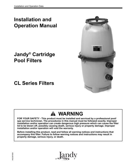
H0238700DInstallation and Operation DataInstallation andOp er a tion Man u al<strong>Jandy</strong> ® Car tridge<strong>Pool</strong> Fil ters<strong>CL</strong> Series Fil tersWARNINGFOR YOUR SAFETY - This product must be installed and serviced by a pro fes sion al pool/spa service technician. The procedures in this manual must be followed ex act ly. Im prop erin stal la tion and/or op er a tion can create dangerous high pres sure which can cause the <strong>filter</strong>lid to be blown off, possibly causing death, serious injury or prop er ty damage. Improperin stal la tion and/or operation will void the war ran ty.Before installing this product, read and follow all warning notices and instructions thataccompany this <strong>filter</strong>. Failure to follow warning notices and instructions may result inproperty damage, serious injury, or death.
Cartridge <strong>Pool</strong> Filters - <strong>CL</strong> Series FilterPage 3TABLE OF CONTENTSSection 1. Safety Information ....................... 41.1 Important Safety Warning ....... 41.2 General Safety Instructions ..... 4Section 2. General Information ..................... 52.1 Introduction ............................. 52.2 Description .............................. 52.3 General Requirements............. 52.4 Specifications and Dimensions 5Section 3. Installation Instructions................ 63.1 Filter Location......................... 63.2 Filter Preparation..................... 63.3 Filter Installation ..................... 73.4 Clamp Installation, <strong>CL</strong> Series . 8Section 4. Start-Up and Operation................ 9Section 5. Filter Disassembly and Assembly 9Section 6. Maintenance................................. 106.1 General Maintenance............... 106.2 Pressure Gauge........................ 106.3 Cleaning the Filter Cartridge... 10Section 7. Winterizing................................... 10Section 8. Troubleshooting ........................... 11Section 9. Parts List and Exploded View...... 12Section 10.Head Loss Curves........................ 13Warranty ...................................................... 16EQUIPMENT INFORMATION RECORDDATE OF INSTALLATIONINITIAL PRESSURE GAUGE READING (WITH <strong>CL</strong>EAN FILTER)PUMP MODELHORSEPOWERFILTER MODELSERIAL NUMBERNOTES:
Page 4Section 1. Safety Information1.1 Important Safety WarningWARNINGNEVER OPERATE OR TEST THE FIL TER SYSTEM AT MORE THAN 50 PSI.THIS FILTER OPERATES UNDER HIGH PRESSURE. WHEN ANY PART OF THECIRCULATING SYSTEM, i.e., FILTER, PUMP, VALVE(S), <strong>CL</strong>AMP, ETC. IS SERVICED,AIR CAN ENTER THE SYSTEM AND BECOME PRESSURIZED WHEN THE SYSTEM ISRESTARTED. PRESSURIZED AIR CAN CAUSE THE FILTER LID TO BE BLOWN OFFWHICH CAN RESULT IN DEATH, SERIOUS PERSONAL INJURY OR PROPERTY DAMAGE.TO AVOID THIS PO TEN TIAL HAZ ARD, FOL LOW ALL OF THE IN STRUC TIONS IN THISMAN U AL.1.2 General Safety InstructionsATTENTION INSTALLER:This manual contains important information about the installation, operation and safe use of thisproduct. This information should be given to the owner/operator of this equip ment.1. Before repositioning valve(s) and before beginning the assembly, disassembly, or adjustment of the clamp, orany other service of the circulating system; (A) turn the pump off and shut off any automatic controls to ensurethe system is not inadvertently started during servicing; (B) open the air release valve; (C) wait until all pressureis relieved (air will have stopped flowing from the air release valve).2. Whenever installing the <strong>filter</strong> clamp follow Section 3.4 of this manual, "Clamp Installation".3. Once service on the circulation system is complete, follow Section 4 of this manual, "Start-up andOperation".4. Maintain circulation system properly. Replace worn or damaged parts immediately.5. Be sure that the <strong>filter</strong> is properly mounted and positioned according to these installation instructions.6. Do not pressure test above 50 PSI. Pressure testing must be done by a trained pool professional.SAVE THESE INSTRUCTIONS.
Cartridge <strong>Pool</strong> Filters - <strong>CL</strong> Series FilterSection 2. General Information2.1 IntroductionThis manual contains information for the proper installationand operation of the <strong>Jandy</strong> ® <strong>CL</strong> Series CartridgeFilters. Procedures in this manual must be followed exactly.To obtain additional copies of this manual contactus at 707.776.8200 ext. 237. For address informationsee back cover.2.2 DescriptionCartridge <strong>filter</strong>s do not require sand or diatomaceousearth as the <strong>filter</strong> medium. Instead, the <strong>filter</strong> contains<strong>filter</strong> elements which are easily removed for cleaning orreplacement.Dirty water flows into the <strong>filter</strong> tank through the waterline connected to the lower bulkhead (inlet) on thebottom half of the tank body. It is directed through the<strong>filter</strong> <strong>cartridge</strong> inside of the <strong>filter</strong>. The debris is collectedin the <strong>filter</strong> and the clean water flows out of the <strong>filter</strong>through the upper bulkhead (outlet) on the bottom halfof the tank body. Clean water is returned through thepiping system to the pool.As debris collects in the <strong>filter</strong>, the pressure will riseand water flow to the pool will diminish. The <strong>filter</strong> willeventually become so plugged with debris that it will benecessary to remove the <strong>filter</strong> <strong>cartridge</strong>s and clean themwith soap and water.NOTE A fi lter removes dirt and other suspended particlesbut does not sanitize the pool. <strong>Pool</strong> water must besanitized and chemically balanced for clear water.The fi ltration system should be designed to meetlocal health codes. At a minimum, the system shouldturnover the total volume of water in your pool two tofour times in a 24 hour period.Page 55. We recommend the use of barrel unionsto connect each component of the waterconditioning system to ease in future servicing.Barell unions are provided with all <strong>Jandy</strong> <strong>filter</strong>s.2.4 Specifications and DimensionsSee Table 1 and Figure 1.Table 1. Cartridge Filter Specifications<strong>CL</strong>340 <strong>CL</strong>460 <strong>CL</strong> 580Filter Area (ft 2 ) 340 460 580Max. Flow (gpm) 127 150 150Six HourCapacity (gal.) 45,720 54,000 54,000Max. WorkingPressure (psi) 50 50 50Normal Start UpPressure (psi) 6-15 6-15 6-15Dimension "A" 41 in. 41 in. 47 in.25 inWARNINGThe maximum working pressure for this fi lter is 50psi. Never subject the fi lter to pressure exceeding 50psi, even when conducting hydrostatic pressure tests.Pressures above 50 psi can cause the lid to be blownoff.6. When performing hydrostatic pressure tests orwhen testing for external leaks of the completedfiltration and plumbing system, ensure thatthe maximum pressure the filtration system issubjected to does not exceed the maximumworking pressure of any of the componentswithin the system.2.3 General Requirements1. For best overall performance place the system asclose to the pool as possible.2. The <strong>filter</strong> should be located on a level concreteslab so that the orientation of the valve outlets andthe pressure gauge are convenient and accessiblefor the installation and operation of the unit.3. Protect the <strong>filter</strong> from the weather.4. If fitting a chlorinator and/or any other device intothe filtration plumbing circuit, great care must bexercised to ensure that the appliance is installed inaccordance with the Manufacturer’s Instructionsand any standards that may exist.Figure 1.OUT LETINLET10 ½ in18½in"A"Dimensions, <strong>Jandy</strong> <strong>CL</strong> Series CartridgeFilters
Page 6Section 3. Installation Instructions3.1 Filter Location1. Select a well-drained area, one that does not floodwhen it rains. Damp, non-ventilated areas shouldbe avoided.2. Provide solid mounting for the <strong>filter</strong> and pumpsystem. Install system on a concrete slab or solidconcrete blocks to avoid risk of settlement. Do notuse sand to level the <strong>filter</strong> as the sand will washaway. Filter systems can weigh up to 800 lbs.3. Install electrical controls at least five (5) feet fromthe <strong>filter</strong>. This will allow enough room to standaway from the <strong>filter</strong> during start-up.4. Allow sufficient clearance around the <strong>filter</strong> topermit a visual inspection of the clamp ring (seeFig. 2).5. Allow sufficient space above the <strong>filter</strong> to removethe <strong>filter</strong> lid and <strong>filter</strong> element for cleaning andservicing.6. Position the <strong>filter</strong> to safely direct water drainage.Align the air release valve to safely direct purgedair or water.WARNINGWater discharged from an improperly positioned fi lteror valve can create an electrical hazard which cancause death, serious injury or property damage.CAUTIONMaintain your pressure gauge in good work ing order.The pressure gauge is the primary indicator of howthe fi lter is operating.7. If the <strong>filter</strong> needs to be located above the waterlevel of the pool, it can be raised 2.5 ft. withoutaffecting the pump efficiency. A check valve isrecommended on the suction line to the pump.8. If the <strong>filter</strong> is to be installed below the water levelof the pool, isolation valves should be installed onboth the suction and return lines to prevent backflow of pool water during any routine servicingthat may be required.3.2 Filter Preparation1. Check carton for damage due to rough handlingin shipment. If carton or any <strong>filter</strong> components aredamaged, notify carrier immediately.2. Carefully remove the accessory package.3. A visual inspection of all parts should be madenow. See parts list on page 12.4. With the carton in an upright position, remove the<strong>filter</strong> tank from the carton.5. To mount the pressure gauge/air release assemblyto the top of the <strong>filter</strong> tank (located in the accessorybag):a. Place the smaller, thicker o-ring onto thethreads of the tank adapter (see Fig. 3). Slidethe tank adapter through the coupling nut andinto the <strong>filter</strong> tank. Use the flats on the tankadapter to tighten. Do not overtighten.b. Place the larger, thinner o-ring onto the gaugehousing. Thread the housing into the coupleron the tank adapter.c. Orient the gauge/air release assembly in thedesired position. Raise and thread the locknutonto the bottom of the gauge/air releaseassembly. Hand tighten the nut only. Usinga wrench to tighten the nut may damage thenut, gauge or air release assembly.6" MINIMUM <strong>CL</strong>EARANCEFILTER6" MINIMUM<strong>CL</strong>EARANCEHousingO-RingTank AdapterTank Adapter to HousingCouplerO-RingFigure 2.Filter LocationFigure 3.Pressure Gauge/Air Release Assembly
Cartridge <strong>Pool</strong> Filters - <strong>CL</strong> Series FilterPage 7Laars HeaterOutlet PortSpa Make UpInlet PortWaterfall<strong>Jandy</strong>CheckValve<strong>Jandy</strong> FilterFrom <strong>Pool</strong>Drain<strong>Jandy</strong> PumpSpa Return<strong>Pool</strong> ReturnSpa SuctionFrom <strong>Pool</strong> SkimmerFigure 4.Basic <strong>Pool</strong>/Spa Combination Plumbing3.3 Filter Installation1. This <strong>filter</strong> operates under pressure. When clampedproperly and operated without air in the watersystem, this <strong>filter</strong> will operate in a safe manner.2. If doubt exists as to the pressure which the systemwill be subjected to, install an ASME approvedautomatic Pressure Relief Valve or PressureRegulator in the circulation system set to thelowest working pressure of any of the componentsin the system.3. Place the <strong>filter</strong> on the concrete pad, lined up withthe inlet/outlet pipes (see Fig. 4).line leaks may cause air to be entrapped in <strong>filter</strong>tank or loss of prime at the pump. Pump dischargeline leaks may show up as dampness or jets ofwater.8. Support the inlet/outlet pipes independently toprevent any undue strains on the <strong>filter</strong> valve.9. Connect the pipes using the unions supplied withthe <strong>filter</strong>. Do not use teflon tape or pipe dope onany unions. Assemble the unions dry and handtighten.4. To reduce pressure losses, 2" (minimum) piping isrecommended for plumbing the system.5. For best efficiency use the fewest possible numberof fittings. This will prevent a restriction in thewater flow.6. Make all plumbing connections in accordancewith local plumbing and building codes. Filterconnections are provided with an o-ring seal. Toavoid damage to the o-rings, use only a siliconebase lubricant on the o-rings. Do not use pipe jointcompound, glue or solvent on inlet/outlet unioncoupling nuts.7. Keep piping tight and free of leaks. Pump suction
Page 8WARNINGFollow these instructions carefully. Improper clampinstallation can cause the fi lter lid to be blown offwhich can result in death, serious personal injury orproperty dam age.Clamp Ring3.4 Clamp Installation, <strong>CL</strong> Series1. Be certain the o-ring is in position in the lowertank half. Press the <strong>filter</strong> lid over the lower halfsandwiching the o-ring between the two halves.2. Holding the ends of the <strong>filter</strong> clamp apart, positionthe hinged segment of the <strong>filter</strong> clamp over bothupper and lower tank flanges. Bring the ends of the<strong>filter</strong> clamp together.Figure 5."T" Nut andThreaded RodFilter Clamp RingTightening Nutw/ Shoulder3. Place the "T" nut and threaded rod assembly intothe clamp. Be sure the "T" nut is seated in theclamp in the proper orientation (See Fig. 6).4. Use a 9/16" socket on the tightening nut until theclamp ring halves touch each other, or are within1/16" (See Fig. 6) but do not overtighten as theclamp can break. If unable to tighten as indicated,do not operate the <strong>filter</strong> and call a servicetechnician immediately."T" NutThread edRodTighteningNut w/Shoulder5. After the first week of operation, check the clampand retighten if necessary.6. Check the <strong>filter</strong> clamp at least once a month.ClampRingTighteningNut w/ShoulderUse a 9/16" SocketClamp Ring,Closed PositionGAP NOT TO EXCEED1/16"Figure 6.Filter Clamp Ring Assembly
Cartridge <strong>Pool</strong> Filters - <strong>CL</strong> Series FilterSection 4. Start-Up and OperationNOTE This section applies to both new pool and seasonalstart-up.WARNINGNEVER start pump while standing within fi ve (5)feet of the fi lter. Starting the pump while there ispressurized air in the system can cause the fi lterlid to be blown off, which can cause death, se ri ouspersonal injury or property damage.WARNINGNEVER operate the fi lter system at more than 50 psiof pressure. Operating the fi lter system in excess of50 psi can cause the fi lter lid to be blown off, whichcan cause death, serious personal injury or propertydamage.CautionDO NOT operate fi lter at water temperatures above120° F (65.5° C). Water temperatures above themanufacturer's recommendations will shorten the lifespan of the fi lter and void the warranty.1. Turn off the pump. Switch off the circuit breakerto the pump motor.2. Check that the drain plug is in place and tight.3. Check that the tank clamp is correctly seated andtight (See Figs. 5 and 6).4. Open the pump hair/lint pot lid and fill the pumpbasket with water to prime the system. Replace thelid. (You may have to do this several times on newand seasonal start-ups.)5. Completely open the air release valve on thegauge/air release assembly by turning the knob onthe back of the assembly fully counterclockwise(do not remove the knob).6. Be sure to open any <strong>filter</strong> isolation valves thatwere installed in the system.7. Stand clear of the <strong>filter</strong> and start the pump tocirculate water through the system. When a steadystream of water starts to come out of the air releasevalve, close the valve.Page 98. Watch the pressure gauge to be sure that thepressure does not exceed 50 psi (with clean<strong>cartridge</strong>s). If the pressure approaches 50 psi,immediately turn the pump off and clean the<strong>filter</strong> <strong>cartridge</strong>s (see Section 6.3). If the pressureremains high after cleaning the <strong>filter</strong>, refer to thetroubleshooting guide on page 11 for possiblecauses and solutions.9. After the pressure gauge has stabilized, turn thebezel ring so that the arrow next to the word"<strong>CL</strong>EAN" aligns with the needle of the gauge. Asthe <strong>filter</strong> cleans the water, and the <strong>cartridge</strong>s beginto clog the pressure begins to increase. When theneedle of the pressure gauge aligns with the arrownext to the word "DIRTY" on the bezel, it is timeto clean the <strong>filter</strong> (see Section 6.3). This indicatesan increased pressure of between 10 and 12 psiabove original starting pressure.WARNINGNEVER attempt to assemble, dis as sem ble or adjustthe fi lter when there is pressurized air in the system.Starting the pump while there is any pressurized airin the system can cause the fi lter lid to be blown off,which can cause death, serious personal injury orproperty dam age.Section 5. Filter Disassembly andAssembly1. Turn off the pump. Switch off the circuit breakerto the pump motor.2. IMPORTANT: Completely open air release valveon top of the <strong>filter</strong> tank to release all pressurefrom inside the tank and system.3. Close the <strong>filter</strong> isolation valves on the system toprevent flooding.4. Remove the drain plug located at the bottom of the<strong>filter</strong> tank and allow the tank to drain.5. Replace the drain plug.6. Loosen the tank clamp ring retainer and removethe clamp ring.7. Remove the top of the <strong>filter</strong> tank by lifting itstraight up until it clears the <strong>cartridge</strong>s on theinside of the tank.8. Remove the manifold assembly by lifting it off ofthe the outlet tube and out of the tank.9. Pull the <strong>cartridge</strong>s out of the <strong>filter</strong> tank and cleanthe <strong>cartridge</strong> using the instructions in Section 6.3.
Page 1010. Using new <strong>cartridge</strong>s or the clean original ones,place the <strong>cartridge</strong>s back into the <strong>filter</strong> tank. Besure that they are correctly seated on the <strong>cartridge</strong>support on the bottom of the tank.11. Inspect the o-ring at the top of the outlet tube forcracks and wear marks. Replace if necessary.12. Reinstall the manifold making sure that it fitssquarely over the <strong>cartridge</strong>s and outlet tube.13. Inspect the tank o-ring for cracks or wear marks.Replace if necessary. Place the o-ring back ontothe <strong>filter</strong> bottom.14. Place the <strong>filter</strong> lid onto the <strong>filter</strong> tank bottom.15. Replace the tank clamp ring. See Section 3.4 forclamp installation.16. Start the pump by following the proceduresoutlined in steps 2 through 7 of Section 4.1.Section 6. Maintenance6.1 General Maintenance1. Wash outside of <strong>filter</strong> with a mild detergent andwater. Rinse off with a hose. Do not use solventsto clean the <strong>filter</strong>, solvents will damage the plasticcomponents of the <strong>filter</strong>.2. Check pressure during operation at least once aweek.3. Remove any debris from the skimmer basket andhair/lint pot on pump.4. Check pump and <strong>filter</strong> for any leaks. If any leaksdevelop, turn off the pump and call a qualifiedpool service technician.5. Product safety signs or labels should beperiodically inspected and cleaned by the productuser as necessary to maintain good legibility forsafe viewing distance.6. Product safety signs or labels should be replacedby the product user when a person with normalvision, including corrected vision, is no longerable to read the safety signs or label message paneltext at a safe viewing distance from the hazard.In cases where the product has an extensiveexpected life or is exposed to extreme conditions,the product user should contact either the productmanufacturer or some other source to determinemeans for obtaining replacement signs or labels.6.2 Pressure GaugeCautionMaintain your pressure gauge in good working order.The pressure gauge is the primary indicator of howthe fi lter is operating.1. During operation of the filtration system, checkthe pressure gauge/air release assembly for air orwater leaks at least once a week.2. Keep the pressure gauge in good working order.If you suspect a problem with the gauge, <strong>Jandy</strong>recommends you call a qualified service technicianto do any work on the <strong>filter</strong>/pump system.6.3 Cleaning the Filter Cartridge1. Follow the procedures outlined in steps 1 through8 of Section 5.1 to expose the <strong>cartridge</strong> elementsinside the <strong>filter</strong>.2. Remove <strong>cartridge</strong> elements and place them uprightin an area suitable for washing.3. Use a garden hose and nozzle to wash each pleatof each element.NOTE Algae, suntan oil, calcium and body oils can formcoatings on fi lter element which may not be removedby normal hosing. To remove such materials, soakthe element in de-greaser and then a de-scaler. Yourlocal pool dealer will be able to recommend suitableproducts.4. Inspect each <strong>cartridge</strong> for holes, tears orexcessively worn pleats. Replace if necessary.5. To reassemble the <strong>filter</strong> with the new or clean<strong>cartridge</strong>s follow the procedure outlined in steps10 through 16 of Section 5.Section 7. Winterizing1. Turn off the pump and circuit breakers.2. Open air release valve on top of the <strong>filter</strong>.3. Remove the drain plug at the base of the <strong>filter</strong> toensure that the tank is empty. Store the drain plugand seal in a safe place. Do not reinstall until nextseason at start-up.4. Drain system piping of all water.5. Cover the system with a tarpaulin or plastic sheetto protect it from the weather.7. Installation of new replacement safety signs orlabels should be in accordance with the sign orlabel manufacturer's recommended procedure.
Cartridge <strong>Pool</strong> Filters - <strong>CL</strong> Series FilterPage 11Section 8. Troubleshooting1. For a list of common problems and solutions seethe Troubleshooting Guide below.2. <strong>Jandy</strong> recommends that you call a qualified servicetechnician to do any work on the <strong>filter</strong>/pumpsystem. For technical service call 707.776.8200,ext. 260.Table 2.Troubleshooting GuideFault Symptom Possible Problems SolutionsWater is not clear.Low water flow.Short <strong>filter</strong> cycles.High pressure on start-up.Dirt returns to pool.Insufficient disinfectant level.Incorrect pool chemistry.Heavy bathing and/or dirt loads.Insufficient running times.Filter is dirty.Hole in <strong>filter</strong> element.Filter system strainer baskets dirty.Air leaks on suction side of pump.Restrictions or blockage in either suction orreturn lines.Filter <strong>cartridge</strong>s need to be cleaned orreplaced.<strong>Pool</strong> water level too low.Pump not primed.Pump impeller vanes blocked.Strainer baskets not being used and/orbroken. (Allow debris into pump.)Pump operating under speed (low voltage).Presence of algae clogging <strong>filter</strong>.Incorrect water chemistry.Pump output exceeds design flow rate of<strong>filter</strong>.Ineffective cleaning.Small eyeball fitting in <strong>Pool</strong>/Spa.Partially closed valve on return line.Too large of pump.Filter <strong>cartridge</strong>s dirty.Hole in <strong>filter</strong> <strong>cartridge</strong>.Worn o-ring seal inside <strong>filter</strong>.Check and adjust disinfectant level.Test and adjust water chemistry.Adjust <strong>filter</strong> time and/or water chemistry.Increase pump run time.Clean <strong>filter</strong> <strong>cartridge</strong>s per instructions.Replace <strong>cartridge</strong>.Check and clean strainer baskets.Check all connections between pool intakeand pump.Check all lines for debris or partially closedvalves.Clean or replace <strong>filter</strong> <strong>cartridge</strong>s perinstructions.Fill pool so level is above pump inlet line.Fill pump with water at basket and replace lid.Technician required.Replace baskets.Technician or electrician required.Check disinfectant content.Check pH, total alkalinity and TDS.Check pump performance.Clean or replace <strong>filter</strong> <strong>cartridge</strong> perin struc tions.Replace with larger diameter fitting.Check and fully open all valves on return line.Check pump and <strong>filter</strong> selection.Clean <strong>filter</strong> <strong>cartridge</strong>s per instructions.Replace <strong>filter</strong> <strong>cartridge</strong> per instructions.Replace o-ring.
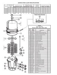
Page 12Section 9. Parts List and ExplodedView9.2 <strong>Jandy</strong> ® <strong>CL</strong> Filters Exploded View9.1 <strong>Jandy</strong> ® <strong>CL</strong> Car tridge Filter Parts ListKeyNo.DescriptionPartNo.1 Handle Assembly w/ hardware (set of 2) R03571002 Handle Hardware (set of 4) R03599003 Gauge/Air Release Assembly R03572004 Pressure Gauge R05696005 Tank Adapter w/O-ring R05520006 Tank Top <strong>CL</strong>580 R0357300Tank Top <strong>CL</strong>340 & <strong>CL</strong>460R05547007 Top Spacer R03577008 Breather Tube Assembly R03587009 Manifold Assembly R035760010 <strong>CL</strong> 580 Filter Cartridge, 145 sq. ft.R0357900(4 required)<strong>CL</strong> 460 Filter Cartridge, 115 sq. ft.R0554600(4 required)<strong>CL</strong> 340 Filter Cartridge, 85 sq. ft.R0554500(4 required)11 Tank Clamp Ring w/Knob Assembly R035740012 Clamp Ring Knob Assembly w/Threaded R0357500Rod and Retainer13 Tank O-ring R035780014 <strong>CL</strong>580 Outlet Tube/Elbow Assembly R0358100w/O-rings<strong>CL</strong>460 & <strong>CL</strong>340 Outlet Tube/Elbow R0555100Assembly w/ O-rings15 Bulkhead Assembly w/O-ring R035820016 Coupling Nuts w/ Flange and O-ring R0327300(set of 2)17 Inlet Elbow w/O-ring R035840018 Tank Bottom w/Drain Plug R035860019 Drain Plug w/O-ring R035880020 Large Tank Drain Adapter w/O-ring R039550021 Filter Cartridge Support R035850022 O-ring Replacement Kit (not shown) R035800023 Ring, Retaining R040520024 Installation/Instruction Manual (not shown) H0238700
Cartridge <strong>Pool</strong> Filters - <strong>CL</strong> Series FilterPage 13Section 10.Head Loss Curves10.1 <strong>Jandy</strong> ® <strong>CL</strong> Car tridge Filter Design HeadLoss Curves
Page 14NOTES
Cartridge <strong>Pool</strong> Filters - <strong>CL</strong> Series FilterPage 15
H0238700DLIMITED WARRANTYThank you for purchasing <strong>Jandy</strong> ® pool and spa products. Water Pik Technologies (manufacturer of <strong>Jandy</strong>products, including Laars ® pool and spa heaters, Air Energy Heat Pumps, and Clormatic Electronic ChlorineGenerators) warrants all parts to be free from manufacturing defects in materials and workmanship for a period ofone year from the date of retail purchase, with the following exceptions:• AquaLink ® RS units installed with <strong>Jandy</strong> Surge Protection Kits will be covered for two years.• NeverLube ® valves are warranted for the life of pool and/or spa on which they were originally installed.• AquaPure TM Electronic Chlorine Generator Electrolytic Cells carry a 5 year limited warranty on a prorated basis.This warranty is limited to the first retail purchaser, is not transferable, and does not apply to products that havebeen moved from their original installation sites. The liability of Water Pik Technologies shall not exceed therepair or replacement of defective parts and does not include any costs for labor to remove and reinstall thedefective part, transportation to or from the factory, and any other materials required to make the repair. Thiswarranty does not cover failures or malfunctions resulting from the following:1. Failure to properly install, operate or maintain the product(s) in accordance with our published Installation,Operation and Maintenance Manuals provided with the product(s).2. The workmanship of any installer of the product(s).3. Not maintaining a proper chemical balance in your pool and/or spa [pH level between 7.2 and 7.8, TotalAlkalinity (TA) between 80 to 120 ppm, Total Dissolved Solids (TDS) less than 2000].4. Abuse, alteration, accident, fire, flood, lightning, rodents, insects, negligence or acts of God.5. Scaling, freezing, or other conditions causing inadequate water circulation.6. Operating the product(s) at water flow rates outside the published minimum and maximum specifications.7. Use of non-factory authorized parts or accessories in conjunction with the product(s).8. Chemical contamination of combustion air or improper use of sanitizing chemicals, such as introducingsanitizing chemicals upstream of the heater and cleaner hose or through the skimmer.9. Overheating, incorrect wire runs; improper electrical supply; collateral damage caused by failure of O-Rings,DE grids, or <strong>cartridge</strong> elements; or damage caused by running the pump with insufficient quantities of water.LIMITATION OF LIABILITY:This is the only warranty given by Water Pik Technologies. No one is authorized to make any other warranties onWater Pik Technologies' behalf. THIS WARRANTY IS IN LIEU OF ALL OTHER WARRANTIES, EXPRESSEDOR IMPLIED, IN<strong>CL</strong>UDING BUT NOT LIMITED TO ANY IMPLIED WARRANTIES OF FITNESS FOR APARTICULAR PURPOSE AND MERCHANTABILITY. WATER PIK TECHNOLOGIES EXPRESSLY DIS<strong>CL</strong>AIMSAND EX<strong>CL</strong>UDES ANY LIABILITY FOR CONSEQUENTIAL, INCIDENTAL, INDIRECT OR PUNITIVEDAMAGES FOR BREACH OF ANY EXPRESSED OR IMPLIED WARRANTY. This warranty gives you specificlegal rights. You may also have other rights which vary by state or province.WARRANTY <strong>CL</strong>AIMS:For prompt warranty consideration, contact your dealer and provide the following information: proof of purchase,model number, serial number and date of installation. The installer will contact the factory for instructionsregarding the claim and to determine the location of the nearest designated service center. If the dealer is notavailable, you can locate a service center in your area by visiting www.jandy.com or by calling our technicalsupport department at (707) 776-8200 extension 260. All returned parts must have a Returned MaterialAuthorization number to be evaluated under the terms of this warranty.A Water Pik Technologies Company6000 Condor Drive • Moorpark, CA USA 93021 • 707.776.8200 • Fax 707.763.7785480 S. Service Road West • Oakville, Ontario, Canada L6K 2H4 • 905.844.8233 • Fax 905.844.2635Litho in U.S.A. © Water Pik Technologies 0404