
You also want an ePaper? Increase the reach of your titles
YUMPU automatically turns print PDFs into web optimized ePapers that Google loves.
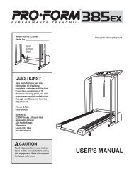
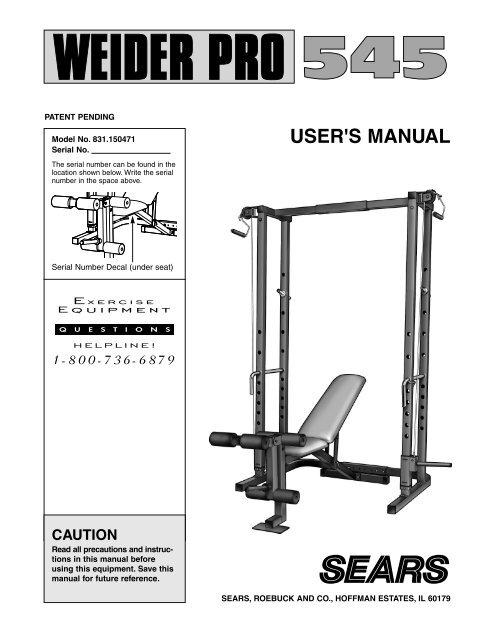
PATENT PENDING<br />
Model No. 831.150471<br />
Serial No.<br />
The serial number can be found in the<br />
location shown below. Write the serial<br />
number in the space above.<br />
Serial Number Decal (under seat)<br />
CAUTION<br />
Read all precautions and instructions<br />
in this manual before<br />
using this equipment. Save this<br />
manual for future reference.<br />
USER'S MANUAL<br />
SEARS, ROEBUCK AND CO., HOFFMAN ESTATES, IL 60179
TABLE OF CONTENTS<br />
IMPORTANT PRECAUTIONS . . . . . . . . . . . . . . . . . . . . . . . . . . . . . . . . . . . . . . . . . . . . . . . . . . . . . . . . . . . . . .3<br />
WARNING DECAL PLACEMENT . . . . . . . . . . . . . . . . . . . . . . . . . . . . . . . . . . . . . . . . . . . . . . . . . . . . . . . . . . .4<br />
BEFORE YOU BEGIN . . . . . . . . . . . . . . . . . . . . . . . . . . . . . . . . . . . . . . . . . . . . . . . . . . . . . . . . . . . . . . . . . . .5<br />
ASSEMBLY . . . . . . . . . . . . . . . . . . . . . . . . . . . . . . . . . . . . . . . . . . . . . . . . . . . . . . . . . . . . . . . . . . . . . . . . . . .6<br />
ADJUSTING THE WEIDER PRO <strong>545</strong> . . . . . . . . . . . . . . . . . . . . . . . . . . . . . . . . . . . . . . . . . . . . . . . . . . . . . . .14<br />
EXERCISE GUIDELINES . . . . . . . . . . . . . . . . . . . . . . . . . . . . . . . . . . . . . . . . . . . . . . . . . . . . . . . . . . . . . . . .17<br />
ORDERING REPLACEMENT PARTS . . . . . . . . . . . . . . . . . . . . . . . . . . . . . . . . . . . . . . . . . . . . . . . .Back Cover<br />
FULL 90 DAY WARRANTY . . . . . . . . . . . . . . . . . . . . . . . . . . . . . . . . . . . . . . . . . . . . . . . . . . . . . . . .Back Cover<br />
Note: A PART IDENTIFICATION CHART and a PART LIST/EXPLODED DRAWING are attached to the center of<br />
this manual. Remove the PART IDENTIFICATION CHART and the PART LIST/EXPLODED DRAWING before<br />
beginning assembly.<br />
2
IMPORTANT PRECAUTIONS<br />
WARNING: To reduce the risk of serious injury, read the following important precautions before using<br />
the weight bench.<br />
1. Read all instructions in this manual before<br />
using the weight bench.<br />
2. Use the weight bench only as described in<br />
this manual.<br />
3. It is the responsibility of the owner to ensure<br />
that all users of the weight bench are adequately<br />
informed of all precautions.<br />
4. Use the weight bench only on a level surface.<br />
Cover the floor beneath the weight bench for<br />
<strong>pro</strong>tection.<br />
5. Inspect and tighten all parts each time you<br />
use the weight bench. Replace any worn<br />
parts immediately.<br />
6. Keep children under 12 and pets away from<br />
the weight bench at all times.<br />
7. Keep hands and feet away from moving parts.<br />
8. Always wear athletic shoes for foot <strong>pro</strong>tection<br />
while exercising.<br />
9. Do not use a barbell (not included) longer<br />
than six feet when the squat rack is set to<br />
the narrow width. If you are using an olympic<br />
barbell (not included) you must set the squat<br />
rack to the wide width.<br />
3<br />
10. Always be sure there is an equal amount of<br />
weight on each side of your barbell (not<br />
included) when you are using it.<br />
11. The weight bench is designed to support a<br />
maximum of 560 pounds, including the user,<br />
a weight bar, and weights. Do not place more<br />
than 310 pounds, including a weight bar and<br />
weights, on the weight rests; do not place<br />
more than 75 pounds on each weight carriage;<br />
do not place more than 150 pounds on<br />
the leg lever for normal use.<br />
12. When using the backrest, make sure that the<br />
“L” pin is fully inserted through the adjustment<br />
bracket and the frame on the bench.<br />
13. Always exercise with a partner. When you are<br />
performing bench press exercises, squat<br />
exercises, or toe raise exercises, your partner<br />
should stand behind you to catch the barbell<br />
if you cannot complete a repetition.<br />
14. The weight bench is intended for home use<br />
only. Do not use the weight bench in any<br />
commercial, rental, or institutional setting.<br />
15. If you feel pain or dizziness at any time while<br />
exercising, stop immediately and begin cooling<br />
down.<br />
WARNING: Before beginning this or any exercise <strong>pro</strong>gram, consult your physician. This is especially<br />
important for persons over the age of 35 or persons with pre-existing health <strong>pro</strong>blems. Read all<br />
instructions before using. SEARS assumes no responsibility for personal injury or <strong>pro</strong>perty damage<br />
sustained by or through the use of this <strong>pro</strong>duct.
WARNING DECAL PLACEMENT<br />
The decal shown below has been placed on the weight bench and on the squat rack. If either decal is<br />
missing, or if either decal is not legible, please call our toll-free HELPLINE at 1-800-736-6879, Monday<br />
through Saturday, 7 a.m. until 7 p.m. Central Time (excluding holidays), to order a free replacement decal.<br />
Apply the replacement decal to the location shown.<br />
4
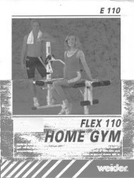
BEFORE YOU BEGIN<br />
Thank you for selecting the WEIDER ® PRO <strong>545</strong> Weight<br />
Bench. The versatile PRO <strong>545</strong> Weight Bench is<br />
designed to be used with your own weight set (not<br />
included) to develop every major muscle group of the<br />
body. Whether your goal is a shapely figure, dramatic<br />
muscle size and strength, or a healthier cardiovascular<br />
system, the PRO <strong>545</strong> Weight Bench will help you to<br />
achieve the specific results you want.<br />
For your benefit, read this manual carefully before<br />
using the WEIDER ® PRO <strong>545</strong> Weight Bench. If you<br />
have additional questions, please call our toll-free<br />
Pulley<br />
Station<br />
Handle<br />
Weight Rest<br />
Spotter Tube<br />
Weight Carriage<br />
Leg Lever<br />
Weight Tube<br />
Foot Plate<br />
SQUAT RACK<br />
Adjustment<br />
“U” Bracket<br />
WEIGHT BENCH<br />
5<br />
HELPLINE at 1-800-736-6879, Monday through<br />
Saturday, 7 a.m. until 7 p.m. Central Time (excluding<br />
holidays). To help us assist you, please note the <strong>pro</strong>duct<br />
model number and serial number before calling.<br />
The model number is 831.150471. The serial number<br />
can be found on a decal attached to the PRO <strong>545</strong><br />
Weight Bench (see the front cover of this manual).<br />
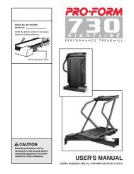
Before reading further, please review the drawing<br />
below and familiarize yourself with the parts that are<br />
labeled.<br />
Adjustment<br />
“U” Bracket<br />
Pulley<br />
Station<br />
Handle<br />
Weight Rest<br />
Spotter Tube<br />
Backrest<br />
Seat<br />
Adjustment Bracket<br />
Weight Tube<br />
Weight Carriage
ASSEMBLY<br />
Before beginning assembly, carefully read the<br />
following information and instructions:<br />
• Assembly requires two people.<br />
• Place all parts in a cleared area and remove the<br />
packing materials; do not dispose of the packing<br />
materials until assembly is completed.<br />
• Tighten all parts as you assemble them, unless<br />
instructed to do otherwise.<br />
• For help identifying the small parts used in<br />
assembly, use the PART IDENTIFICATION<br />
CHART attached at the center of the manual.<br />
• As you assemble the weight bench, be sure that<br />
all parts are oriented as shown in the drawings.<br />
1. Before assembling this <strong>pro</strong>duct, be sure that<br />
you have read and understand the information<br />
in the box above.<br />
Press a 50mm Square Outer Cap (40) onto each<br />
side of the Stabilizer (33).<br />
Attach the Stabilizer (33) to the Bench Frame (49)<br />
with two M8 x 68mm Bolts (8), two M8 Washers<br />
(13) and two M8 Nylon Locknuts (12).<br />
2. Press a 50mm Square Inner Cap (36) into each end<br />
of the Front Leg (22).<br />
Attach the Front Leg (22) to the Bench Frame (49)<br />
with two M8 x 68mm Bolts (8), two M8 Washers<br />
(13) and two M8 Nylon Locknuts (12).<br />
6<br />
THE FOLLOWING TOOLS (NOT INCLUDED) ARE<br />
REQUIRED FOR ASSEMBLY:<br />
• Two (2) adjustable wrenches<br />
• One (1) rubber mallet<br />
• One (1) standard screwdriver<br />
• One (1) phillips screwdriver<br />
• Lubricant, such as grease or petroleum jelly,<br />
and soapy water will also be needed.<br />
Assembly will be more convenient if you have the<br />
following tools: A socket set, a set of open-end or<br />
closed-end wrenches, or a set of ratchet wrenches.<br />
1<br />
2<br />
12<br />
36<br />
13<br />
49<br />
36<br />
22<br />
40<br />
8<br />
8<br />
13<br />
33<br />
49<br />
12<br />
40
3. Press 20mm x 40mm Inner Caps (44) into the ends<br />
of both Backrest Tubes (25).<br />
Lubricate an M10 x 152mm Bolt (11). Attach the<br />
Backrest Tubes (25) to the Bench Frame (49) with<br />
the Bolt and an M10 Nylon Locknut (14). See the<br />
inset drawing. The indicated hole in the<br />
Backrest Tube (25) is slightly off center. The<br />
Backrest Tube must be oriented as shown, when<br />
it is attached to the Bench Frame (49). Do not<br />
overtighten the Nylon Locknut; the Backrest<br />
Brackets must be able to move freely.<br />
4. Slide the Adjustment Bracket (26) onto the Bench<br />
Frame (49). See the inset drawing. The guide rod<br />
inside the Adjustment Bracket must be on the indicated<br />
side of the welded tube in the Bench Frame.<br />
Align one set of holes in the Adjustment Bracket<br />
(26) with the hole in the Bench Frame (49). Insert<br />
the “L” Pin (46) through the Adjustment Bracket and<br />
the Bench Frame.<br />
Lubricate an M10 x 152mm Bolt (11). Attach the<br />
Adjustment Bracket (26) to the Backrest Tubes (25)<br />
with the Bolt, two Adjustment Bracket Spacers (50),<br />
and an M10 Nylon Locknut (14). Do not overtighten<br />
the Nylon Locknut; the Backrest Brackets<br />
and Adjustment Bracket must be able to move<br />
freely.<br />
5. Attach the Backrest (29) to the Backrest Tubes (25)<br />
with four M6 x 48mm Screws (35) and four M6<br />
Washers (42). Note: Before you attach the Backrest<br />
to the Backrest Tubes, look at the back side of the<br />
Backrest. You will notice that one set of threaded<br />
holes is closer to the end of the Backrest (see the<br />
inset drawing). This end of the Backrest must be<br />
closest to the Bench Frame (49).<br />
6. Attach the Seat (34) to the Bench Frame (49) with<br />
the M6 x 60mm Screw (16), two M6 x 16mm<br />
Screws (17), and three M6 Washers (42).<br />
7<br />
3<br />
44<br />
4<br />
5<br />
49<br />
6<br />
14<br />
29<br />
14<br />
44<br />
25<br />
11—Lubricate<br />
Lubricate—11<br />
25 50<br />
26<br />
49<br />
35<br />
34<br />
49<br />
42<br />
42 17<br />
16<br />
44<br />
25<br />
35<br />
46<br />
42<br />
25<br />
49<br />
42<br />
49<br />
Guide<br />
Rod<br />
49<br />
26<br />
Hole must<br />
be on the<br />
lower side<br />
Welded<br />
Tube<br />
46<br />
This end of the<br />
Backrest must<br />
be closest to the<br />
Bench Frame
7. Press three 50mm Square Inner Caps (36) into the<br />
Leg Lever (32). Press a 1” Round Inner Cap (41)<br />
into the Leg Lever. Press a 1” Angle Cap (5) onto<br />
the Leg Lever.<br />
8. Lubricate the M10 x 75mm Bolt (10). Attach the Leg<br />
Lever (32) to the Front Leg (22) with the Bolt and<br />
an M10 Nylon Locknut (14).<br />
9. Tap 3/4” Round Inner Caps (43) into each end of<br />
the three Pad Tubes (38).<br />
Insert a Pad Tube (38) through one hole in the Leg<br />
Lever (32). Insert another Pad Tube through the<br />
other hole in the Leg Lever. Insert the remaining<br />
Pad Tube through the upper hole in the Front Leg<br />
(22).<br />
Slide two Foam Pads (48) onto each Pad Tube (38).<br />
10. Set each section of the Base (20, 55) on the floor.<br />
Be sure that the indented side of each section of<br />
the Base is facing the floor. Press a 50mm Square<br />
Inner Cap (36) into the indicated end of each section<br />
of the Base.<br />
Insert four M8 x 58mm Carriage Bolts (6) into each<br />
section of the Base (20, 55).<br />
8<br />
7<br />
8<br />
9<br />
48<br />
43<br />
10<br />
36<br />
32<br />
38<br />
48<br />
36<br />
41<br />
48<br />
20<br />
14<br />
43<br />
43<br />
6<br />
32<br />
38<br />
6<br />
6<br />
22<br />
Upper<br />
Hole<br />
43<br />
32<br />
36<br />
22<br />
38<br />
5<br />
10—Lubricate<br />
43<br />
6<br />
48<br />
48<br />
55<br />
The indented<br />
side must face<br />
the floor
11. Note: The WEIDER PRO <strong>545</strong> is designed to be<br />
used with both olympic and standard barbells. If you<br />
will be using an olympic barbell, assemble the base<br />
in the wide position, as shown in the main drawing.<br />
If you will be using a standard barbell, assemble the<br />
base in the narrow position, as shown in the inset<br />
drawing.<br />
Attach each section of the Base (20, 55) to an<br />
Adjustment “U” Bracket (31) with two M8 x 68mm<br />
Bolts (8) and two M8 Nylon Locknuts (12). Do not<br />
tighten the Nylon Locknuts yet.<br />
12. Slide a Rear Upright (19) onto the indicated M8 x<br />
58mm Carriage Bolts (6) in either section of the<br />
Base (20, 55). The Rear Upright must be oriented<br />
as shown, with the indicated holes facing forward.<br />
A second person must hold the Upright at<br />
the location shown during the step. Partially<br />
tighten an M8 Nylon Locknut (12) onto each<br />
Carriage Bolt but do not fully tighten the Nylon<br />
Locknut. Note: The heads of the Carriage Bolts<br />
must lock into the square holes in each section<br />
of the Base in order to tighten the Nylon<br />
Locknuts; you may need to slide your fingers<br />
under the Base to hold the Carriage Bolts in<br />
place while you partially tighten the Nylon<br />
Locknuts.<br />
Assemble the other Rear Upright (19) in the same<br />
manner.<br />
13. Press 1” Round Inner Caps (41) into the ends of the<br />
Weight Rests (37).<br />
9<br />
11<br />
12<br />
13<br />
20<br />
8 8<br />
20<br />
19<br />
12<br />
55<br />
31<br />
41<br />
6<br />
37<br />
8<br />
31<br />
8<br />
These holes<br />
must face<br />
forward<br />
20<br />
19<br />
41<br />
12<br />
55<br />
6<br />
12<br />
12<br />
A second person must hold<br />
each Upright here while the<br />
Nylon Locknuts are attached<br />
55
14. Insert a Weight Rest (37) into each Rear Upright<br />
(19). Be sure that the Weight Rests are inserted<br />
at the same level on both sides.<br />
15. Slide a Front Upright (18) onto the indicated M8 x<br />
58mm Carriage Bolts (6) in either section of the<br />
Base (20, 55). A second person must hold the<br />
Upright at the location shown during the step.<br />
Partially tighten an M8 Nylon Locknut (12) onto<br />
each Carriage Bolt but do not fully tighten the<br />
Nylon Locknut. Note: The heads of the Carriage<br />
Bolts must lock into the square holes in each<br />
section of the Base in order to tighten the Nylon<br />
Locknuts; you may need to slide your fingers<br />
under the Base to hold the Carriage Bolts in<br />
place while you partially tighten the Nylon<br />
Locknuts.<br />
Assemble the other Front Upright (18) in the same<br />
manner.<br />
16. Press two 60mm Square Bushings (53) into a<br />
Weight Carriage (52). Press a 1” Round Inner Cap<br />
(41) into the Weight Carriage.<br />
Assemble the other Weight Carriage (52) in the<br />
same manner.<br />
Press a 60mm Square Bushing (53) into the<br />
Carriage Stop (54). The drilled hole in the Square<br />
Bushing must be aligned with the drilled hole in<br />
the Carriage Stop.<br />
10<br />
14<br />
15<br />
16<br />
41<br />
37<br />
18<br />
12<br />
19<br />
6<br />
52<br />
53<br />
20<br />
55<br />
37<br />
18<br />
12<br />
19<br />
A second person<br />
must hold each<br />
Upright here while<br />
the Nylon Locknuts<br />
are attached<br />
53<br />
54<br />
6<br />
53<br />
Align<br />
these<br />
holes
17. Slide a Carriage Stop (54) onto a Front Upright<br />
(18). Be sure that the 60mm Square Bushing<br />
(53) is facing up. Align the holes in the Carriage<br />
Stop with the holes in the Front Upright. Insert<br />
an M8 x 68mm Bolt (8) through the Carriage Stop<br />
and Front Upright. Tighten an M8 Nylon Locknut<br />
(12) onto the Bolt.<br />
Slide a Weight Carriage (52) onto the Front Upright<br />
(18). The weight tube must be on the side<br />
shown.<br />
Attach the other Carriage Stop (54) and Weight<br />
Carriage (52) in the same manner.<br />
18. Press two 50mm Square Inner Caps (36) into each<br />
section of the Top Frame (21, 39).<br />
Note: As in step 11, if you will be using an olympic<br />
barbell, assemble the top frame in the wide position,<br />
as shown in the main drawing. If you will be<br />
using a standard barbell, assemble the top frame in<br />
the narrow position, as shown in the inset drawing.<br />
Attach each section of the Top Frame (21, 39) to<br />
the other Adjustment “U” Bracket (31) with two M8 x<br />
68mm Bolts (8) and two M8 Nylon Locknuts (12).<br />
Do not tighten the Nylon Locknuts yet.<br />
If you are assembling each section of the Top<br />
Frame (21, 39) in the wide position, attach the<br />
Spacer Tube (1) inside the Adjustment “U” Bracket<br />
(31) with two M8 x 68mm Bolts (8) and two M8<br />
Nylon Locknuts (12). Do not tighten the Nylon<br />
Locknuts yet.<br />
Note: If you are assembling each section of the<br />
Top Frame (21, 39) in the narrow position, store<br />
the Spacer Tube (1), the two extra M8 x 68mm<br />
Bolts (8), and the two extra M8 Nylon Locknuts<br />
(12) in a safe place. If you ever purchase an<br />
olympic barbell, you will need these parts (see<br />
ADJUSTING THE WIDTH OF THE SQUAT RACK<br />
on page 16).<br />
11<br />
17<br />
18<br />
52<br />
54<br />
36<br />
31<br />
18<br />
8<br />
21<br />
53<br />
21<br />
8 8<br />
39<br />
12<br />
31<br />
36<br />
8<br />
12<br />
18<br />
52<br />
8<br />
36<br />
12<br />
8<br />
54<br />
39<br />
1<br />
36
19. Attach each section of the Top Frame (21, 39) to<br />
the Front Uprights (18) with an M8 x 68mm Bolt (8),<br />
two M8 Washers (13), and an M8 Nylon Locknut<br />
(12).<br />
Attach each section of the Top Frame (21, 39) to<br />
the Rear Uprights (19) with two M8 x 68mm Bolts<br />
(8), two M8 Washers (13), and two M8 Nylon<br />
Locknuts (12).<br />
Tighten all Nylon Locknuts and Bolts used in<br />
steps 11–19.<br />
20. Attach a Cable (51) to one of the Weight Carriages<br />
(52) with an M10 x 75mm Bolt (10), two Cable<br />
Spacers (45), and an M10 Nylon Locknut (14).<br />
Attach the other Cable to the other Weight Carriage<br />
(not shown) in the same manner.<br />
21. Lubricate an M10 x 90mm Bolt (7). Attach a “U”<br />
Bracket (30) to Top Frame B (39) with the Bolt and<br />
an M10 Nylon Locknut (14). Do not overtighten<br />
the Nylon Locknut.<br />
Attach the other “U” Bracket to Top Frame A (not<br />
shown) in the same manner<br />
22. Wrap the indicated Cable (51) around a Pulley (24).<br />
Attach the Pulley to the “U” Bracket (30) with an<br />
M10 x 48mm Bolt (9), a Cable Trap (23), and an<br />
M10 Nylon Locknut (14). The Cable must be routed<br />
around the Pulley from the direction shown.<br />
The Cable Trap should be attached on the outside<br />
of the “U” Bracket and should be turned to<br />
hold the Cable in place.<br />
Assemble the other Pulley to the other “U” Bracket<br />
(not shown) in the same manner.<br />
12<br />
19<br />
20<br />
21<br />
22<br />
8<br />
18<br />
8<br />
21<br />
9<br />
12<br />
13<br />
30<br />
45<br />
45<br />
10 14<br />
52<br />
39<br />
51<br />
14<br />
12<br />
19<br />
13<br />
8<br />
18<br />
30<br />
39<br />
8<br />
12<br />
13<br />
7—Lubricate<br />
14<br />
23<br />
24<br />
51<br />
19<br />
12<br />
13
23. Press a 1” Round Inner Cap (41) into each end of a<br />
Spotter Tube (4).<br />
Press a 1” Round Inner Cap into each end of the<br />
other Spotter Tube (not shown).<br />
24. Insert a Spotter Tube (4) through a Front Upright<br />
(18) and into a Rear Upright (19). Rotate the<br />
Spotter Tube so that the hook locks in place around<br />
the Front Upright.<br />
Insert the other Spotter Tube through the other<br />
Front and Rear Upright (not shown) in the same<br />
manner. Be sure that the Spotter Tubes are<br />
inserted at the same level on both sides.<br />
25. Attach the indicated Handle (27) to one of the<br />
Cables (51) by inserting the hook on the end of the<br />
Handle through the loop in the end of the Cable.<br />
Attach the other Handle to the other Cable (not<br />
shown) in the same manner.<br />
26. Make sure that all parts are <strong>pro</strong>perly tightened before you use the weight bench.<br />
13<br />
23<br />
24<br />
25<br />
Loop<br />
Hook<br />
41<br />
4<br />
4<br />
18<br />
19<br />
51<br />
41<br />
27
ADJUSTING THE WEIDER PRO <strong>545</strong><br />
The weight bench is designed to be used with your own weight set (not included). The steps below explain how<br />
the weight bench can be adjusted. See EXERCISE GUIDELINES on page 17 for important exercise information<br />
and refer to the accompanying exercise poster to see the correct form for each exercise. Refer also to the exercise<br />
information accompanying your weight set (not included) for additional exercises.<br />
Inspect and tighten all parts each time you use the weight bench. Replace any worn parts immediately. The<br />
weight bench can be cleaned with a damp cloth and a mild, non-abrasive detergent. Do not use solvents.<br />
ADJUSTING THE BACKREST<br />
The Backrest (29) can be set at four different positions:<br />
the level position, the decline position, and two incline<br />
positions.<br />
To change the position of the Backrest (29), remove the<br />
“L” Pin (46) from the Adjustment Bracket (26) and the<br />
Bench Frame (49). Set the Backrest to the desired position,<br />
align the holes in the Adjustment Bracket and the<br />
Bench Frame, and re-insert the “L” Pin.<br />
ATTACHING WEIGHTS TO THE WEIGHT CARRIAGE<br />
To use the pulley station, slide the desired amount of<br />
weight (not included) onto the weight tube on each<br />
Weight Carriage (52). Be sure there is an equal amount<br />
of weight on each Weight Carriage. Secure the weights<br />
on each Weight Carriage with a Spring Clip (47).<br />
WARNING: Do not place more than 75 pounds<br />
on each weight carriage.<br />
ATTACHING WEIGHTS TO THE LEG LEVER<br />
To use the Leg Lever (32), slide the desired amount of<br />
weight (not included) onto the weight tube. Secure the<br />
weight with a Spring Clip (47).<br />
WARNING: Do not place more than 150 pounds<br />
on the leg lever.<br />
14<br />
Weight<br />
Weight<br />
47<br />
52<br />
32<br />
29<br />
Weight Tube<br />
26<br />
46<br />
Weight Tube<br />
49<br />
47
ADJUSTING THE WEIGHT RESTS<br />
Squat exercises and toe raise exercises naturally<br />
require that the Weight Rests (37) be set to a different<br />
height than bench press exercises. You should always<br />
set the Weight Rests to a height which is comfortable<br />
for the exercise you will perform.<br />
To adjust the Weight Rests (37), insert the Weight Rests<br />
into the adjustment holes in the Rear Uprights (19) at<br />
the desired height. Be sure that each Weight Rest is<br />
firmly seated in the adjustment hole and that both<br />
Weight Rests are at the same height.<br />
WARNING: Do not place more than 310 pounds,<br />
including a weight bar and weights, on the<br />
weight rests.<br />
ADJUSTING THE SPOTTER TUBES<br />
To perform bench press exercises, squat exercises or<br />
toe raise exercises (see the accompanying EXERCISE<br />
POSTER) you will need to set the Spotter Tubes (4) at<br />
a level which is just below the lowest point that the barbell<br />
(not included) will travel during the exercise. The<br />
Spotter Tubes can help reduce the risk of injury if you<br />
cannot complete a repetition while exercising.<br />
WARNING: Always exercise with a partner. When<br />
you are performing bench press exercises,<br />
squat exercises or toe raise exercises, your partner<br />
should stand behind you to catch the barbell<br />
if you cannot complete a repetition.<br />
To adjust the Spotter Tubes (4), insert the Spotter Tubes<br />
through the adjustment holes in the Front Uprights (18)<br />
and into the adjustment holes in the Rear Uprights (19)<br />
at the desired height. Rotate each Spotter Tube so<br />
that the hook locks in place around each Front<br />
Upright. Be sure that the Spotter Tubes are inserted<br />
at the same level on both sides.<br />
15<br />
37<br />
4<br />
18<br />
Adjustment<br />
Holes<br />
19<br />
Adjustment<br />
Holes
ADJUSTING THE POSITION OF THE PAD TUBE<br />
For some exercises you may want to move the Pad<br />
Tube (38) to the lower hole in the Front Leg (22). For<br />
other exercises you will want to leave the Pad Tube in<br />
the upper hole. For different exercises you should select<br />
the position which is most comfortable for you.<br />
ADJUSTING THE WIDTH OF THE SQUAT RACK<br />
If you buy a new barbell, you may need to change the<br />
width of the squat rack. If you are using an olympic<br />
barbell, you must use the wide setting. If you are<br />
using a five or six foot long barbell, you must use<br />
the narrow setting.<br />
To move the squat rack from the narrow setting to<br />
the wide setting: Remove the Adjustment “U” Bracket<br />
(31), four M8 x 68mm Bolts (8), and four M8 Nylon<br />
Locknuts (12) from each section of the Base (20, 55).<br />
Remove the Adjustment “U” Bracket (31), four M8 x<br />
68mm Bolts (8), and four M8 Nylon Locknuts (12) from<br />
each section of the Top Frame (21, 39). Re-assemble<br />
the Base and Top Frame in the wide position, as shown<br />
in the main drawing. Attach the Spacer Tube (1) inside<br />
the upper Adjustment “U” Bracket (31) with two M8 x<br />
68mm Bolts (8) and two M8 Nylon Locknuts (12).<br />
To move the squat rack from the wide setting to the<br />
narrow setting: Remove the Adjustment “U” Bracket<br />
(31), four M8 x 68mm Bolts (8), and four M8 Nylon<br />
Locknuts (12) from each section of the Base (20, 55).<br />
Remove the Adjustment “U” Bracket (31), six M8 x<br />
68mm Bolts (8), six M8 Nylon Locknuts (12), and the<br />
Spacer Tube (1) from each section of the Top Frame<br />
(21, 39). Re-assemble the Base in the narrow position,<br />
as shown in drawing A. Re-assemble the Top Frame in<br />
the narrow position, as shown in drawing B. Save the<br />
Spacer Tube (1), the two extra M8 x 68mm Bolts (8),<br />
and the two extra M8 Nylon Locknuts (12) for future<br />
use. A<br />
WARNING: Do not use a barbell longer than six<br />
feet when the squat rack is set to the narrow<br />
width. If you are using an olympic barbell you<br />
must set the squat rack to the wide width.<br />
16<br />
21<br />
20<br />
8 8<br />
31<br />
38<br />
55<br />
31<br />
12<br />
8<br />
8<br />
Upper<br />
Hole<br />
20<br />
B<br />
31<br />
22<br />
Lower<br />
Hole<br />
31<br />
21<br />
1<br />
39<br />
12<br />
8 8<br />
39<br />
12<br />
55
EXERCISE GUIDELINES<br />
THE FOUR BASIC TYPES OF WORKOUTS<br />
• Muscle Building<br />
In order to increase the size and strength of your<br />
muscles, you must push your muscles to a high percentage<br />
of their capacity. You must also <strong>pro</strong>gressively<br />
increase the intensity of your exercise so that your<br />
muscles will continually adapt and grow. Each individual<br />
exercise can be tailored to the <strong>pro</strong>per intensity<br />
level by changing the amount of weight used, or the<br />
number of repetitions or sets performed. (A “repetition”<br />
is one complete cycle of an exercise, such as<br />
one sit-up. A “set” is a series of repetitions performed<br />
consecutively.)<br />
The <strong>pro</strong>per amount of weight for each exercise<br />
depends upon the individual user. It is up to you to<br />
gauge your limits. Select the amount of weight that<br />
you think is right for you. Begin with 3 sets of 8 repetitions<br />
for each exercise that you perform. Rest for 3<br />
minutes after each set. When you can complete 3 sets<br />
of 12 repetitions without difficulty, increase the amount<br />
of weight.<br />
• Toning<br />
To tone your muscles, you must push your muscles to<br />
a moderate percentage of their capacity. Select a<br />
moderate amount of weight and increase the number<br />
of repetitions in each set. Complete as many sets of<br />
15 to 20 repetitions as possible without discomfort.<br />
Rest for 1 minute after each set. Work your muscles<br />
by completing more sets rather than by using high<br />
amounts of weight.<br />
• Weight Loss<br />
To lose weight, use a low amount of weight and<br />
increase the number of repetitions in each set.<br />
Exercise for 20 to 30 minutes, resting for a maximum<br />
of 30 seconds between sets.<br />
• Cross Training<br />
In the pursuit of a complete and well-balanced fitness<br />
<strong>pro</strong>gram, many have found that cross training is the<br />
answer. We recommend that on Monday, Wednesday<br />
and Friday, you plan weight training workouts. On<br />
Tuesday and Thursday, plan 20 to 30 minutes of aerobic<br />
exercise, such as cycling, running or swimming.<br />
Rest from both weight training and aerobic exercise<br />
for at least one full day each week to give your body<br />
time to regenerate. By combining weight training with<br />
aerobic exercise, you can reshape and strengthen<br />
your body, plus develop a stronger heart and lungs.<br />
17<br />
PERSONALIZING YOUR EXERCISE PROGRAM<br />
We have not specified an exact length of time for<br />
each workout, or a specific number of repetitions or<br />
sets for each exercise. It is very important to avoid<br />
overdoing it during the first few months of your exercise<br />
<strong>pro</strong>gram, and to <strong>pro</strong>gress at your own pace. If<br />
you experience pain or dizziness at any time while<br />
exercising, stop immediately and begin to cool down.<br />
Find out what is wrong before continuing. Remember<br />
that adequate rest and a <strong>pro</strong>per diet are also important.<br />
WARMING UP<br />
Begin each workout with 5 to 10 minutes of light<br />
stretching and exercise to warm up. Warming up prepares<br />
your body for exercise by increasing circulation,<br />
raising your body temperature and delivering more<br />
oxygen to your muscles.<br />
WORKING OUT<br />
Each workout should include 6 to 10 different exercises.<br />
Select exercises for every major muscle group,<br />
with emphasis on the areas that you want to develop<br />
the most. To give balance and variety to your workouts,<br />
vary the exercises from workout to workout.<br />
Schedule your workouts for the time of day when your<br />
energy level is the highest. Each workout should be<br />
followed by at least one day of rest. Once you find the<br />
schedule that is right for you, stick with it.<br />
EXERCISE FORM<br />
In order to obtain the greatest benefits from exercising,<br />
it is essential to maintain <strong>pro</strong>per form.<br />
Maintaining <strong>pro</strong>per form means moving through the<br />
full range of motion for each exercise, and moving<br />
only the ap<strong>pro</strong>priate parts of the body. Exercising in<br />
an uncontrolled manner will leave you feeling exhausted.<br />
On the exercise poster accompanying this manual,<br />
you will find photographs showing the correct form for<br />
several exercises. A description of each exercise is<br />
also <strong>pro</strong>vided, along with a list of the muscles affected.<br />
Refer to the muscle chart on page 18 to find the<br />
locations of the muscles.<br />
The repetitions in each set should be performed<br />
smoothly and without pausing. The exertion stage of<br />
each repetition should last about half as long as the<br />
return stage. Proper breathing is important. Exhale<br />
during the exertion stage of each repetition and inhale<br />
during the return stroke; never hold your breath. Rest
for 3 minutes after each set if you are doing a muscle<br />
building workout, 1 minute after each set if you are<br />
doing a toning workout, and 30 seconds after each<br />
set if you are doing a weight loss workout. Plan to<br />
spend the first couple of weeks familiarizing yourself<br />
with the equipment and learning the <strong>pro</strong>per form for<br />
each exercise.<br />
COOLING DOWN<br />
End each workout with 5 to 10 minutes of stretching.<br />
Include stretches for both your arms and legs. Move<br />
slowly as you stretch—do not bounce. Ease into each<br />
stretch gradually and go only as far as you can without<br />
strain. Stretching at the end of each workout is<br />
very effective for increasing flexibility.<br />
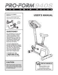
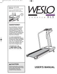
MUSCLE CHART<br />
A. Sternomastoid (neck)<br />
B. Pectoralis Major (chest)<br />
C. Biceps (front of arm)<br />
D. Obliques (waist)<br />
E. Brachioradials (forearm)<br />
F. Hip Flexors (upper thigh)<br />
G. Abductor (outer thigh)<br />
H. Quadriceps (front of thigh)<br />
I. Sartorius (front of thigh)<br />
J. Tibialis Anterior (front of calf)<br />
K. Soleus (front of calf)<br />
L. Rectus Abdominus (stomach)<br />
M. Adductor (inner thigh)<br />
N. Trapezius (upper back)<br />
O. Rhomboideus (upper back)<br />
P. Deltoid (shoulder)<br />
Q. Triceps (back of arm)<br />
R. Latissimus Dorsi (mid back)<br />
S. Spinae Erectors (lower back)<br />
T. Gluteus Medius (hip)<br />
U. Gluteus Maximus (buttocks)<br />
V. Hamstring (back of leg)<br />
W. Gastrocnemius (back of calf)<br />
A<br />
B<br />
C<br />
D<br />
E<br />
H<br />
I<br />
J<br />
K<br />
G<br />
F<br />
18<br />
STAYING MOTIVATED<br />
For motivation, keep a record of each workout. The<br />
chart on page 19 of this manual can be photocopied<br />
and used to schedule and record your workouts. List<br />
the date, exercises performed, weight, and numbers<br />
of sets and repetitions completed. Record your weight<br />
and key body measurements at the end of every<br />
month.<br />
Remember, the key to achieving the greatest results<br />
is to make exercise a regular and enjoyable part of<br />
your everyday life.<br />
L<br />
M<br />
T<br />
N<br />
O<br />
P<br />
Q<br />
R<br />
S<br />
U<br />
V<br />
W
MONDAY<br />
Date:<br />
/ /<br />
TUESDAY<br />
Date:<br />
/ /<br />
WEDNESDAY<br />
Date:<br />
/ /<br />
THURSDAY<br />
Date:<br />
/ /<br />
FRIDAY<br />
Date:<br />
/ /<br />
EXERCISE WEIGHT SETS REPS<br />
AEROBIC EXERCISE<br />
EXERCISE WEIGHT SETS REPS<br />
AEROBIC EXERCISE<br />
EXERCISE WEIGHT SETS REPS<br />
Make photocopies of this page for scheduling and recording your workouts.<br />
19
M10 x 48mm Bolt (9)—2<br />
M8 Nylon Locknut (12)—30 M10 Nylon Locknut (14)—9<br />
M6 Washer (42)—7<br />
M6 x 60mm Screw (16)—1<br />
M6 x 16mm Screw (17)—2<br />
M8 x 68mm Bolt (8)—22<br />
M10 x 152mm Bolt (11)—2<br />
M8 Washer (13)—12<br />
M6 x 48mm Screw (35)—4<br />
M10 x 90mm Bolt (7)—2<br />
M8 x 58mm CarriageBolt (6)—8<br />
M10 x 75mm Bolt (10)—3
3/8" Dome Cap (3)—2 3/4" Round Inner Cap (43)—6<br />
1” Angle Cap (5)—1<br />
50mm Square Outer Cap (40)—2<br />
60mm Square Bushing (53)—6<br />
1" Round Inner Cap (41)—11<br />
20mm x 40mm Inner Cap (44)—4<br />
50mm Square Inner Cap (36)—11
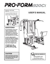
PART LIST—Model No. 831.150471 R0997A<br />
Key Part<br />
No. Qty. No. Description<br />
1 1 139870 Spacer Tube<br />
2 2 139871 Foam Grip<br />
3 2 139872 3/8” Dome Cap<br />
4 2 139873 Spotter Tube<br />
5 1 139874 1” Angle Cap<br />
6 8 139875 M8 x 58mm Carriage Bolt<br />
7 2 139876 M10 x 90mm Bolt<br />
8 22 139877 M8 x 68mm Bolt<br />
9 2 139878 M10 x 48mm Bolt<br />
10 3 130287 M10 x 75mm Bolt<br />
11 2 139880 M10 x 152mm Bolt<br />
12 30 139881 M8 Nylon Locknut<br />
13 12 139882 M8 Washer<br />
14 9 139883 M10 Nylon Locknut<br />
15 - - - - - - Not Used<br />
16 1 140207 M6 x 60mm Screw<br />
17 2 140208 M6 x 16mm Screw<br />
18 2 140209 Front Upright<br />
19 2 140210 Rear Upright<br />
20 1 140211 Base A<br />
21 1 140212 Top Frame A<br />
22 1 141606 Front Leg<br />
23 2 140214 Cable Trap<br />
24 2 140215 Pulley<br />
25 2 140216 Backrest Tube<br />
26 1 140218 Adjustment Bracket<br />
27 2 140219 Handle<br />
28 2 140220 Handgrip<br />
29 1 140221 Backrest<br />
Key Part<br />
No. Qty. No. Description<br />
30 2 140222 “U” Bracket<br />
31 2 140222 Adjustment “U” Bracket<br />
32 1 140223 Leg Lever<br />
33 1 140224 Stabilizer<br />
34 1 140225 Seat<br />
35 4 140226 M6 x 48 Screw<br />
36 11 140227 50mm Square Inner Cap<br />
37 2 140228 Weight Rest<br />
38 3 140229 Pad Tube<br />
39 1 140230 Top Frame B<br />
40 2 140231 50mm Square Outer Cap<br />
41 11 140232 1” Round Inner Cap<br />
42 7 140233 M6 Washer<br />
43 6 140234 3/4” Round Inner Cap<br />
44 4 140235 20mm x 40mm Inner Cap<br />
45 4 140236 Cable Spacer<br />
46 1 140237 “L” Pin<br />
47 2 140238 Spring Clip<br />
48 6 140239 Foam Pad<br />
49 1 140240 Bench Frame<br />
50 2 140241 Adjustment Bracket Spacer<br />
51 2 140242 Cable<br />
52 2 140243 Weight Carriage<br />
53 6 140244 60mm Square Bushing<br />
54 2 140245 Carriage Stop<br />
55 1 140246 Base B<br />
# 1 141602 User’s Manual<br />
# 1 131065 Exercise Poster<br />
Note: “#” indicates a non-illustrated part. Specifications are subject to change without notice. See the back cover<br />
of this manual for information about ordering replacement parts.
21<br />
31<br />
23<br />
24<br />
51<br />
27<br />
28<br />
2<br />
3<br />
30<br />
53<br />
51<br />
52<br />
53<br />
54<br />
18<br />
19<br />
37<br />
20<br />
31<br />
48<br />
48<br />
5<br />
32<br />
22<br />
38<br />
48<br />
48<br />
38<br />
48<br />
34<br />
49<br />
25<br />
29<br />
26<br />
33<br />
54<br />
53<br />
52<br />
53<br />
51<br />
39<br />
30<br />
23<br />
24<br />
51<br />
27<br />
28<br />
2<br />
3<br />
19<br />
37<br />
18<br />
4<br />
55<br />
9<br />
14<br />
7<br />
14<br />
36<br />
36<br />
8<br />
13<br />
45<br />
45<br />
41<br />
10<br />
14<br />
13<br />
8 13<br />
12<br />
12<br />
41<br />
41<br />
41<br />
8<br />
12<br />
12<br />
12<br />
6<br />
6<br />
8<br />
12<br />
36<br />
41<br />
36<br />
43<br />
43<br />
43<br />
36<br />
14<br />
10<br />
36<br />
13<br />
12<br />
36<br />
8<br />
8<br />
12<br />
12<br />
8<br />
8<br />
16 17<br />
8<br />
40<br />
40<br />
12<br />
13<br />
14<br />
11<br />
44<br />
35<br />
46<br />
11<br />
14<br />
35<br />
44<br />
50<br />
8<br />
13<br />
7<br />
36<br />
36<br />
14<br />
45<br />
14<br />
10<br />
41<br />
12<br />
12<br />
12<br />
13<br />
8<br />
41<br />
41<br />
41<br />
41<br />
12<br />
12<br />
8<br />
6<br />
6<br />
12<br />
9<br />
14<br />
47<br />
4<br />
41<br />
42<br />
42<br />
42<br />
42<br />
50<br />
36<br />
36<br />
8<br />
12<br />
1<br />
EXPLODED DRAWING—Model No. 831.150471 R0997A
Model No. 831.150471<br />
QUESTIONS?<br />
If you find that:<br />
• you need help assembling or<br />
operating the WEIDER ® PRO <strong>545</strong><br />
• a part is missing<br />
• or you need to schedule repair<br />
service<br />
call our toll-free HELPLINE<br />
1-800-736-6879<br />
Monday–Saturday, 7 am–7 pm<br />
Central Time (excluding holidays)<br />
REPLACEMENT<br />
PARTS<br />
If parts become worn and need to<br />
be replaced, call the following tollfree<br />
number<br />
1-800-FON-PART<br />
(1-800-366-7278)<br />
The model number and serial number of your WEIDER ® PRO <strong>545</strong><br />
are listed on a decal attached to the frame. See the front cover of<br />
this manual to find the location of the decal.<br />
All replacement parts are available for immediate purchase or<br />
special order when you visit your nearest SEARS Service Center.<br />
To request service or to order parts by telephone, call the toll-free<br />
numbers listed at the left.<br />
When requesting help or service, or ordering parts, please be prepared<br />
to <strong>pro</strong>vide the following information:<br />
• The MODEL NUMBER of the <strong>pro</strong>duct (831.150471).<br />
• The NAME of the <strong>pro</strong>duct (WEIDER ® PRO <strong>545</strong> Weight Bench).<br />
• The PART NUMBER of the PART (see the PART LIST and the<br />
EXPLODED DRAWING at the center of this manual).<br />
• The DESCRIPTION of the PART (see the PART LIST and the<br />
EXPLODED DRAWING at the center of this manual).<br />
FULL 90 DAY WARRANTY<br />
For 90 days from the date of purchase, if failure occurs due to defect in material or workmanship in this<br />
SEARS WEIGHT BENCH EXERCISER, contact the nearest SEARS Service Center throughout the<br />
United States and SEARS will repair or replace the WEIGHT BENCH EXERCISER, free of charge.<br />
This warranty does not apply when the WEIGHT BENCH EXERCISER is used commercially or for rental<br />
purposes.<br />
This warranty gives you specific legal rights, and you may also have other rights which vary from state<br />
to state.<br />
SEARS, ROEBUCK AND CO., DEPT. 817WA, HOFFMAN ESTATES, IL 60179<br />
Part No. 141602 G03215AC R0997B Printed in China © 1997 Sears, Roebuck and Co.