Modeling and Simulation of IEEE 14-bus System - Electrical and ...
Modeling and Simulation of IEEE 14-bus System - Electrical and ...
Modeling and Simulation of IEEE 14-bus System - Electrical and ...

You also want an ePaper? Increase the reach of your titles
YUMPU automatically turns print PDFs into web optimized ePapers that Google loves.
CHAPTER 1. BLOCK DIAGRAM MODELING 15<br />
Input Signal<br />
Reference<br />
Set Point<br />
Input<br />
Signal<br />
Stability<br />
Control Loop<br />
Steady State<br />
Control Loop<br />
X<br />
X<br />
m<br />
+<br />
Σ<br />
+<br />
eo<br />
X’<br />
m<br />
X<br />
1 + s T<br />
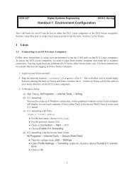
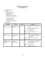
Figure 1.13: TCSC model for stability studies.<br />
k s T<br />
w w<br />
1 + s T<br />
w<br />
1 + s T<br />
1 + s T<br />
1<br />
2<br />
1 + s T<br />
1 + s T<br />
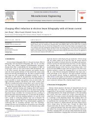
Figure 1.<strong>14</strong>: Block diagram <strong>of</strong> the TCSC stability control loop.<br />
The general structure <strong>of</strong> the stability controller is shown in Figure 1.<strong>14</strong> [20]. It<br />
consists <strong>of</strong> a washout filter, a dynamic compensator, <strong>and</strong> a limiter. The washout<br />
filter is used to avoid a controller response to the dc <strong>of</strong>fest <strong>of</strong> the input signal.<br />
The dynamic compensator consists <strong>of</strong> two (or more) lead-lag blocks to provide<br />
the necessary phase-lead characteristics. Finally, the limiter is used to improve<br />
controller response to large deviations in the input signal.<br />
emin<br />
3<br />
4<br />
1<br />
X<br />
emax<br />
X<br />
e<br />
X