Modeling and Simulation of IEEE 14-bus System - Electrical and ...
Modeling and Simulation of IEEE 14-bus System - Electrical and ...
Modeling and Simulation of IEEE 14-bus System - Electrical and ...

You also want an ePaper? Increase the reach of your titles
YUMPU automatically turns print PDFs into web optimized ePapers that Google loves.
CHAPTER 2. TOOLS AND SIMULATION RESULTS 29<br />
Voltage (p.u.)<br />
1.4<br />
1.2<br />
1<br />
0.8<br />
0.6<br />
0.4<br />
0.2<br />
HB<br />
*<br />
0<br />
0 0.1 0.2 0.3 0.4 0.5 0.6<br />
Base Case<br />
Line 2−4 Outage<br />
Line 2−3 Outage<br />
0.7 0.8<br />
λ<br />
Operating Points<br />
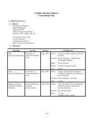
Figure 2.10: P-V curves at <strong>bus</strong> <strong>14</strong> for different contingencies for <strong>IEEE</strong> <strong>14</strong>-<strong>bus</strong> test<br />
system with a TCSC in line 4-5.<br />
controller parameters are given in Appendix B (a 40 % compensation level is as-<br />
sumed in this case). The placement <strong>of</strong> TCSC controller proposed in [25], i.e. in<br />
series with line 4-5, is used for the studies presented here.<br />
•<br />
Figure 2.10 shows the P-V curve for the system with the TCSC controller for<br />
the base case <strong>and</strong> two line outages. Observe that the TCSC controller positively<br />
affects the SLM <strong>and</strong> DLM <strong>of</strong> the test system, as illustrated in Table 2.3.<br />
Figures 2.11 <strong>and</strong> 2.12 present the effect <strong>of</strong> the TCSC controller on the dynamic<br />
HB<br />
*<br />
*<br />
HB