Modeling and Simulation of IEEE 14-bus System - Electrical and ...
Modeling and Simulation of IEEE 14-bus System - Electrical and ...
Modeling and Simulation of IEEE 14-bus System - Electrical and ...

You also want an ePaper? Increase the reach of your titles
YUMPU automatically turns print PDFs into web optimized ePapers that Google loves.
Chapter 1<br />
BLOCK DIAGRAM MODELING<br />
1.1 Introduction<br />
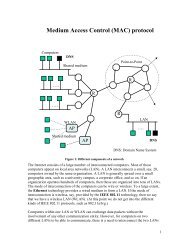
A single line diagram <strong>of</strong> the <strong>IEEE</strong> <strong>14</strong>-<strong>bus</strong> st<strong>and</strong>ard system extracted from [1] is<br />
shown in Figure 1.1. It consists <strong>of</strong> five synchronous machines with <strong>IEEE</strong> type-1<br />
exciters, three <strong>of</strong> which are synchronous compensators used only for reactive power<br />
support. There are 11 loads in the system totaling 259 MW <strong>and</strong> 81.3 Mvar. The<br />
dynamic data for the generators exciters was selected from [2].<br />
The <strong>IEEE</strong> <strong>14</strong>-BUS was studied using the UWPFLOW <strong>and</strong> PST programs to<br />
obtain the system P-V curves <strong>and</strong> perform time domain <strong>and</strong> eigenvalue analyses to<br />
study the general performance <strong>of</strong> the system. SVC, TCSC <strong>and</strong> PSS controllers were<br />
also added to the system, as shown in Figure 1.2, to study their effect in the system<br />
<strong>and</strong> their interactions. The model details are discussed in the following sections,<br />
<strong>and</strong> the corresponding data is given in Appendices A <strong>and</strong> B.<br />
1