1957 chevrolet sedan - Classic Auto Air
1957 chevrolet sedan - Classic Auto Air
1957 chevrolet sedan - Classic Auto Air

Create successful ePaper yourself
Turn your PDF publications into a flip-book with our unique Google optimized e-Paper software.
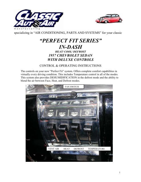
specializing in “AIR CONDITIONING, PARTS AND SYSTEMS” for your classic<br />
vehicle<br />
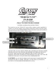
“PERFECT FIT SERIES”<br />
IN-DASH<br />
HEAT/ COOL/ DEFROST<br />
<strong>1957</strong> CHEVROLET SEDAN<br />
WITH DELUXE CONTROLS<br />
CONTROL & OPERATING INSTRUCTIONS<br />
The controls on your new “Perfect Fit” system. Offers complete comfort capabilities in<br />
virtually every driving condition. This includes Temperature control in all of the modes.<br />
This system also provides DEHUMIDIFICATION in the defrost mode and the ability to<br />
blend the air between Face, Heat, and Defrost modes.<br />
FAN SWITCH<br />
VENT AIR HEAT DEFROST TEMPERATURE<br />
1
THE PICTURE YOU SEE ON THE FIRST PAGE SHOWS THE CONTROLS IN THE<br />
A/C POSITION. THIS MEANS THAT THE AIR WILL BE DISTRIBUTED THROUGH<br />
THE FACE OUTLETS. THIS ALSO HAS THE TEMPERATURE LEVER IN THE<br />
COLDEST POSITION. WITH THE CONTROLS IN THIS POSITION YOU WILL GET<br />
THE AIR THROUGH THE FACE OUTLETS AND THE OUTLET TEMPERATURE<br />
AT THE COLDEST POSSIBLE POINT.<br />
CAUTION: ALL OF THE OUTSIDE VENTS MUST BE CLOSED WHEN THE<br />
SYSTEM IS IN THE A/C MODE. THIS WILL ALLOW THE A/C SYSTEM TO<br />
FUCTION AT ITS MAXIMUM PERFORMANCE LEVEL.<br />
THE FOLLOWING SUMMARY WILL DESCRIBE EACH OF THE CONTROL<br />
LEVERS FUNCTION.<br />
FAN SPEED SWITCH: There are 3 speeds plus Off. When the switch is in the off<br />
position it will disconnect the 12V power to the Blower Motor and the A/C Clutch. This<br />
will shut down the entire system. When the switch is moved to any of the blower speeds 1,<br />
2 or 3 there is 12V supplied to the Micro-Switch that is mounted on the distribution<br />
housing.<br />
AIR / VENT CONTROL: Original driver’s fresh air cable.<br />
HEAT CONTROL: When the Control Knob is PUSHED to the bottom position the air<br />
is distributed to the HEAT outlets and the drivers and passenger outlets. When the knob is<br />
PULLED to the TOP the air is distributed to the FACE outlets. This is the A/C mode and<br />
will engage the compressor. The lever can be moved any position from the top to the<br />
bottom. This will give blend between the face and the heat outlets.<br />
DEFROST CONTROL: When the Control Knob is pushed all the way to the bottom<br />
the air is distributed to the DEFROST outlets.<br />
NOTE: THE HEAT LEVER MUST BE IN THE TOP POSITION TO HAVE<br />
DEHUMIDIFIED DEFROST.<br />
TEMPERATURE CONTROL: The Temperature Knob as shown is in the<br />
COLDEST temperature position. As the lever is PUSHED down the temperature of the<br />
discharged air will rise to the HOTTEST point.<br />
Note: The temperature lever will function in any of the modes.<br />
2
specializing in “AIR CONDITIONING, PARTS AND SYSTEMS” for your classic<br />
vehicle<br />
“PERFECT FIT”<br />
IN-DASH<br />
HEAT/ COOL/ DEFROST<br />
<strong>1957</strong> CHEVROLET SEDAN<br />
CONTROL & OPERATING INSTRUCTIONS<br />
The controls on your new “Perfect Fit” system. Offers complete comfort capabilities in<br />
virtually every driving condition. This includes Temperature control in all of the modes.<br />
This system also provides DEHUMIDIFICATION in the defrost mode and the ability to<br />
blend the air between Face and Heat / Defrost modes.<br />
BLOWER SWITCH<br />
A/C CABLE HEAT CABLE TEMPERATURE CABLE<br />
THE PICTURE YOU SEE ABOVE SHOWS THE CONTROLS IN THE DEFROST<br />
MODE. THIS MEANS THAT THE AIR WILL BE DISTRIBUTED THROUGH THE<br />
DEFROST OUTLETS. THIS ALSO HAS THE TEMPERATURE LEVER IN THE<br />
COLD POSITION. WITH THE CONTROLS IN THIS POSITION YOU WILL GET<br />
THE AIR THROUGH THE DEFROST OUTLETS WITH THE COMPRESSOR ON.<br />
3
CAUTION: ALL OF THE OUTSIDE VENTS MUST BE CLOSED WHEN THE<br />
SYSTEM IS IN THE A/C MODE. THIS WILL ALLOW THE A/C SYSTEM TO<br />
FUCTION AT ITS MAXIMUM PERFORMANCE LEVEL.<br />
THE FOLLOWING SUMMARY WILL DESCRIBE EACH OF THE CONTROL<br />
LEVERS FUNCTION.<br />
FAN SPEED SWITCH: There are 3 speeds plus Off. When the switch is in the off<br />
position it will disconnect the 12V power to the Blower Motor and the A/C Clutch. This<br />
will shut down the entire system. When the switch is moved to any of the blower speeds<br />
1,2 or 3 there is 12V supplied to the Micro-Switches that are mounted on the Face Duct.<br />
HEAT CABLE: When the knob is pulled OUT the air will go to the floor. The knob<br />
can be moved any position from the IN position to all of the way OUT. This will give<br />
blend between the defrost and the heat outlets.<br />
A/C CABLE: When the Knob is pulled OUT the air is distributed to the Face outlets.<br />
In the OUT position the Compressor clutch is engaged and you have A/C.<br />
NOTE: The heat control must be in the OUT position.<br />
DEFROST MODE: When the heat control is pushed IN the air will be distributed to<br />
the defrost outlet.<br />
NOTE: In order to get dehumidified defrost the a/c control must be pulled OUT. This will<br />
engage the clutch.<br />
TEMPERATURE CONTROL: The Temperature Knob as shown is in the<br />
COLDEST temperature position. As the lever is pulled out the temperature of the<br />
discharged air will rise to the HOTTEST point.<br />
Note: The temperature lever will function in any of the modes.<br />
4
specializing in “AIR CONDITIONING, PARTS AND SYSTEMS” for your classic<br />
vehicle<br />
INSTALLATION INSTRUCTIONS<br />
<strong>1957</strong> CHEVROLET SEDAN<br />
Congratulations! ! You have just purchased the highest quality, best performing A/C system<br />
ever designed for you <strong>Classic</strong> Car. To obtain the high level of performance and dependability<br />
our systems are known for, pay close attention to the following instructions.<br />
Before beginning the installation check the box for the correct components.<br />
Evaporator<br />
Face Duct Assembly<br />
Flex Hose 2”dia. x 3ft.<br />
Flex Hose 2”dia. x 4ft.<br />
Sack Kit Hardware<br />
Sack Kit Control (2)<br />
Glove Box<br />
Firewall Blockoff<br />
IMPORTANT INFORMATION<br />
1. Before starting, read the instructions carefully and follow proper sequence.<br />
2. Check condition of engine mounts. Excessive engine movement can damage<br />
hoses to A/C, heater, radiator, transcooler, and power steering systems.<br />
3. Before starting, check vehicle interior electrical functions. i.e. interior lights,<br />
radio, horn, etc. When ready to start installation, disconnect battery.<br />
4. Fittings. Use one or two drops of lubricant on O’rings, threads and rear of bump<br />
for O’ring where female nut rides. Do not use thread tape or sealants.<br />
5. Always use two wrenches to tighten fittings. Try holding in one hand while<br />
squeezing together while other hand holds fitting in position.<br />
6. Shaft seals in a small percentage of compressors will require as much as 3-4<br />
hours run time to become leak free.<br />
7. Compressors supplied in our complete systems are filled with proper amount of<br />
oil.<br />
8. Compressor requires technician to hand turn 15-20 revolutions before and after<br />
charging with liquid from a charging station before running system.<br />
Compressors with damaged reed valves cannot be warranted.<br />
9. Should you have any technical questions, or are suspect of missing, or defective<br />
parts, call us immediately. Our knowledgeable staff will be glad to assist you.<br />
YOU CAN NOW BEGIN THE INSTALLATION<br />
5
Locate the glove box.<br />
Remove the glove box<br />
door and glove box.<br />
Discard glove box and<br />
retain all of the original<br />
hardware.<br />
CAUTION: DISCONNECT BATTERY CABLES<br />
Locate battery next to the radiator, remove and retain original hardware.<br />
DRAIN RADIATOR<br />
The next few steps are for the Deluxe Heater.<br />
Remove the heater hoses from the<br />
heater core and water valve.<br />
Discard the original hose clamps.<br />
Remove and discard original water<br />
valve. Retain original hardware.<br />
Locate in hardware sack kit the<br />
water valve cover plate. Attach<br />
using original hardware.<br />
Remove (3) screws as shown. Discard<br />
hardware.<br />
REMOVE (3) SCREWS<br />
6
Located on top of the heater box is the<br />
electrical resistor connection. Disconnect<br />
wiring.<br />
Located on both sides of blower you will find the<br />
Heater Box Retaining brackets.<br />
Remove and retain these brackets . The blower<br />
assembly can now be removed and discarded.<br />
NOTE: Retain Heater Box Retainer brackets.<br />
Locate behind the glove box opening the Heat /<br />
Defrost cable. Disconnect the cable and discard<br />
hardware.<br />
7
NOTE: FOLLOWING STEPS ARE TYPICAL<br />
DRIVERS AND PASSENGERS SIDE OF<br />
VEHICLE. VEHICLES EQUIPT WITH<br />
DELUXE CONTROLS DO NOT REMOVE<br />
DRIVERS CABLE.<br />
Located in the engine compartment and under<br />
fender behind hood hinge spring is the Fresh<br />
<strong>Air</strong> cable.<br />
Disconnect cable and retain hardware.<br />
VENT CABLE<br />
Located under the heater box and<br />
around edge to the top (4) screws.<br />
Remove and discard hardware.<br />
Remove the Heater Box Assembly<br />
and discard.<br />
Locate under Instrument Panel and at<br />
firewall the fresh air inlet grill. Pull<br />
cable previously disconnected under<br />
the hood. On passenger side remove<br />
and discard the grill.<br />
Carefully pull cable into the interior<br />
through the grommet. Retain original<br />
grommet.<br />
8
Locate the control head. Remove<br />
the control. Retain control and<br />
original hardware.<br />
NOTE: When removing the control head identify the power wire to the switch. Label this<br />
wire. The electrical in the new unit will attach to this wire.<br />
VENT CABLE<br />
The other end of cable attaches to under side of the<br />
instrument panel. Use (2) of the #10 tek screws.<br />
Note: Attach drivers side now. The passenger side will<br />
set on floor and be attached after new system is<br />
installed.<br />
REMOVE (4) SCREWS<br />
Locate in the Control Sack Kit (2) Vent<br />
Cable Assemblies, and (4) #10 x ¾” tek<br />
screws.<br />
Insert new cable through the hole that<br />
original control cables routed through<br />
above the air inlet.<br />
The cable will attach under the hood<br />
to the fresh air door using original<br />
hardware.<br />
9
NOTE: STANDARD HEATER ONLY<br />
Unscrew original passenger side vent cable from under the dash. Let cable set on<br />
floor of the car. Retain original hardware.<br />
Located on top of the heater box is the<br />
electrical resistor connection. Disconnect<br />
wiring.<br />
Locate under the hood and on<br />
firewall the heater blower motor<br />
assembly.<br />
Remove (3) nuts around motor discard<br />
original hardware. Cut electrical wires.<br />
Remove and discard Heater Assembly.<br />
Locate behind glove box opening the Heat /<br />
Defrost cable. Disconnect the cable and discard<br />
hardware.<br />
PANEL RETAINING BRACKETS<br />
(3) NUTS.<br />
10
Remove and discard the original Control<br />
Assembly.<br />
Remove and retain original hardware.<br />
NOTE: When removing the control head<br />
identify power wire to the switch. Label<br />
this wire. The electrical in the new unit<br />
will attach to this wire.<br />
Remove the Panel Retaining Brackets and retain.<br />
Remove and discard Panel.<br />
ALL MODIFICATIONS TO THE VEHICLE ARE COMPLETE YOU<br />
CAN NOW BEGIN INSTALLING YOUR CLASSIC AIR<br />
“PERFECT FIT SERIES”.<br />
Locate the Firewall Block off Plate.<br />
Attach over the hole in firewall using<br />
original Panel Retaining Brackets.<br />
Locate the Evaporator and set on a bench.<br />
FIREWALL BLOCK OFF<br />
PANEL RETAINING<br />
BRACKETS<br />
11
Locate the Wire Harness supplied in kit and install onto the unit as shown in diagram<br />
below.<br />
WIRING DIAGRAM <strong>1957</strong> CHEVROLET SEDAN<br />
Place evaporator on floor of the car. Locate blue wire<br />
from the thermostat and route through hole to left of<br />
the large hole in the block off plate.<br />
12
Raise Evaporator into position.<br />
Insert Heater Tube hookups<br />
through holes, and also studs on<br />
the mounting brackets through the<br />
firewall Block off Plate and attach<br />
using (4) ¼-20 Flange Nuts.<br />
Located on front of the blower motor is the<br />
Support Bracket.<br />
Attach bracket through the exiting hole using (1)<br />
¼” – 20 x 5/8” hex head screw and flange nut.<br />
Locate above the Evaporator (2) bulk head<br />
fittings. Remove the nuts and o-rings. Insert<br />
these through (2) holes and attach with nuts and<br />
o-rings from engine side of block off plate.<br />
Locate in the hardware sack kit (2) #10 x ¾” hex<br />
washer head tek screws.<br />
Reattach kick panel vent knob as shown.<br />
13
Locate in the Hardware Sack Kit (1) 9”<br />
clear drain hose.<br />
Drill (1) 11/16” dia. hole through firewall<br />
under evaporator and over to the left<br />
approximately 3” and lower than the<br />
drain nipple as shown.<br />
Insert through hole and onto the drain<br />
nipple.<br />
Locate the face duct assembly, and (1) #10<br />
x 5/8” pan head screw.<br />
Locate next longest of the control cables<br />
supplied in kit. Attach to the Face / Defrost<br />
door using (1) #10 x 5/8” pan head screw.<br />
NOTE: CABLE INSERTS INTO THE 3 rd<br />
HOLE FROM THE CENTER OF THE<br />
DOOR.<br />
Locate longest of the control cables supplied in kit.<br />
Push through hole in firewall block off just to left of<br />
the heater tubes. Let cable hang in place.<br />
Locate shortest of the control cables supplied in kit.<br />
Attach to the Face / Heat<br />
door using (1) #10 x 5/8” pan head screw.<br />
NOTE: CABLE INSERTS INTO 3 rd HOLE<br />
FROM THE CENTER OF THE DOOR.<br />
14
Locate the control cable that<br />
connects to Defrost / Face door.<br />
Insert cable between evaporator<br />
and the firewall.<br />
Attach the Center Duct<br />
Assembly to the Evaporator.<br />
DEFROST DIFFUSER<br />
DUCT ASSEMBLY<br />
Locate in the hardware sack kit (2) #10 x<br />
¾” hex head tek screws.<br />
Attach Duct Assembly to bottom of the<br />
dash as shown.<br />
Connect blue wires from micro switch to<br />
the wire harness as shown.<br />
DEFROST / FACE<br />
CABLE<br />
EVAPORATOR<br />
Locate the Center Duct Assembly.<br />
Set on floor under the glove box<br />
opening.<br />
DEFROST HOUSING<br />
ELECTRICAL CONNECTIONS<br />
OUTLET FROM<br />
EVAPORATOR<br />
Be sure that the defrost duct is<br />
aligned with original defrost<br />
diffuser.<br />
15
Locate the Center Louver<br />
Assembly.<br />
Locate in the hardware<br />
sack kit (4) #8 x ½” pan<br />
Head Phillips Screws.<br />
BLOWER MOTOR<br />
Locate the Side Ball Louver and (2) #10 x ¾” hex<br />
head tek screws.<br />
Remove ball assembly from housing. Attach<br />
housing top to under side of the dash as shown.<br />
Reinstall ball louver, locate the 2” dia. flex hose 36”.<br />
Cut 30” of hose and attach it to the Center Duct<br />
outlet as shown.<br />
(4) #8 X ½ PAN HEAD PHILLIPS SCREWS<br />
0n passenger side of dash, above the blower,<br />
locate Black Ground wire from the blower<br />
motor.<br />
Secure to body using (1) #10 x ¾” hex head<br />
tek screw.<br />
Route hose over<br />
to Passenger<br />
side Ball Louver<br />
and attach it to<br />
hose adaptor on<br />
the back.<br />
16
Locate in the hardware sack kit the Drivers<br />
Side Ball Louver Assembly, and (2) #10 x ¾”<br />
hex head tek screws.<br />
Remove ball assembly from housing. Attach<br />
housing top to under side of the dash as shown.<br />
Reinstall ball louver.<br />
Locate behind control opening find the (3)<br />
cables and the wire harness. Pull through the<br />
opening.<br />
Attach the red / white power wire to wire<br />
identified from the original blower switch.<br />
Located on back side of Center Duct<br />
Assembly is the hose adaptor for drivers<br />
side louver.<br />
Cut 42” of 2” dia. flex hose. Attach it over<br />
the hose adaptor and route over and behind<br />
instruments and attach on to Drivers Ball<br />
Louver Assembly.<br />
POWER WIRE<br />
17
NEXT (1 1/2) PAGES ARE FOR THE STANDARD HEATER CONTROL.<br />
CONTROL BEZEL<br />
ASSEMBLY<br />
CONTROL BRACKET<br />
Locate in the Control Sack Kit<br />
the lower control switch<br />
mounting bracket.<br />
Locate (3) Push Pull cables<br />
behind control head.<br />
Insert cable attached to the Defrost / Face door through center hole and attach with nut<br />
provided. Tighten securely.<br />
Insert shortest of the cables that is attached to Heat / Face door through left hole and<br />
attach with nut provided. Tighten securely.<br />
Insert last cable that is hooked to the water valve through right hole and attach with nut<br />
provided. Tighten securely.<br />
Locate the Control Cover Bezel, (3) Cable Knobs and (4) #8 x ½” pan head Phillips<br />
screws. Attach the wire harness to the blower switch per the wiring diagram on page 8.<br />
A/C<br />
KNOB<br />
HEAT KNOB TEMPERTURE KNOB<br />
(4) #8 x ½” SCREWS<br />
18
Place Control bezel over the cable shafts and up into place. Attach to the Instrument<br />
panel through top holes using (2) #8 x ½” pan head phillips screws.<br />
Aline the control cable mounting bracket to lower holes in the control bezel. Attach to<br />
the lower edge of instrument panel using (2) #8 x ½” pan head phillips screws.<br />
Attach Control Knobs to the control shafts as shown above. Tighten securely using an<br />
allen wrench.<br />
NEXT (2) PAGES ARE FOR THE DELUXE HEATER CONTROLS.<br />
Locate the original control head.<br />
Remove blower switch and the original cables.<br />
Retain the original cable clips.<br />
Locate in the control sack kit the Blower<br />
Switch, and (2) #6 pan head screws.<br />
Insert blower switch through face bezel and<br />
locate in the center and against the edge as<br />
shown.<br />
Drill (2) 1/8” dia. holes and attach using the #6<br />
screws.<br />
The light bulb assembly from original<br />
blower switch will be used.<br />
Cut the wire at plug and attach (1) ¼”<br />
male spade connector. Attach bulb<br />
assembly to the original wire harness.<br />
HOLD AGAINST<br />
EDGE.<br />
19
CONTROL KNOB<br />
Locate in the control sack kit the Black<br />
Blower Switch knob.<br />
Attach to the switch as shown.<br />
Holding control head at the opening in<br />
the instrument panel, attach the cables.<br />
Insert cable attached to the Defrost / Face door to lever labeled DEFR. Attach using<br />
original hardware and push nut provided. Tighten securely.<br />
Insert shortest of the cables that is attached to Heat / Face door to lever labeled HEAT.<br />
Attach using original hardware and push nut provided. Tighten securely.<br />
Insert last cable that is hooked to the water valve to right lever. Attach with original<br />
hardware and push nut provided. Tighten securely.<br />
Attach wire harness to the blower switch per the Wiring Diagram on page 8.<br />
Reinstall original control head using the original hardware.<br />
Locate Glove Box provided in the kit, original Glove Box Door and hardware.<br />
Attach glove box door using original hardware.<br />
20
Insert glove box through<br />
opening as shown.<br />
SCREW BOTH SIDES<br />
Attach using (2) original<br />
screws one on both sides.<br />
INSTALL THE COMPRESSOR ADAPTOR KIT AND COMPRESSOR AT THIS<br />
TIME PER THE MANUFACTURERS DIRECTIONS.<br />
NOTE: THIS INSTALL IS CORRECT FOR A 283CID V8 ENGINE, WITH<br />
ALTERNATOR CONVERSION ON DRIVERS SIDE OF VEHICLE.<br />
IF YOUR VEHICLE IS EQUIPTED WITH A DIFFERENT ENGINE PACKAGE<br />
IT WILL BE NECESSARY TO ROUTE THE HOSES DIFFERENT.<br />
21
MOUNTING BRACKET<br />
LT<br />
Locate the radiator bulkhead hole template. Tape the template<br />
to the bulkhead as shown.<br />
Carefully drill the (1) 5/8” dia. hole and the ¾” dia hole.<br />
#10 X ¾” HEX<br />
SCREW<br />
MOUNTING BRACKET<br />
RT<br />
Locate the Condenser supplied in kit, (2) Mounting Brackets Left, (2) Mounting Brackets Right,<br />
and (8) #10 x 3/8” hex head screws.<br />
Attach left and right brackets 4 th hole from the top, and 4 th hole from the bottom.<br />
Turn the condenser over. Locate the Liquid<br />
Tube (Condenser to Drier), Liquid Tube<br />
(Receiver to Bulkhead), Discharge Tube, (3) #6<br />
o-rings, (1) #8 o-ring, Receiver Drier, the Drier<br />
Mounting bracket, and (2) #10 x 3/8” hex head<br />
screws.<br />
Attach components listed above to the<br />
condenser. Install all tubes with o-rings and a<br />
few drops of mineral oil.<br />
22
LOOSEN THE (6) RADIATOR<br />
MOUNTING BOLTS<br />
Place the Condenser Assembly in front of the radiator and insert the mounting brackets between<br />
the radiator and the radiator mounting brackets.<br />
Use the liquid and suction tubes to set the height of the<br />
condenser. Install the bulkhead nuts and tighten securely.<br />
Tighten the radiator mounting bolts.<br />
Locate the Hi / Low Pressure safety switch.<br />
Attach switch to the port on top of the drier using a few<br />
drops of mineral oil. Tighten securely.<br />
23
Route wires through to the engine compartment. Route the wires along discharge hose to the<br />
compressor. Connect the clutch wire to one of the White wires. The other White wire route along<br />
suction hose and attach to blue clutch wire coming from the thermostat.<br />
Locate Discharge Hose and (2) #8 o-rings.<br />
Attach using a few drops of mineral oil.<br />
The 90 deg. end with service port goes on compressor<br />
and other end is connected to fitting at the bulkhead.<br />
Locate the Suction tube, tube support bracket,<br />
clamp, and #10 x ½ screw and nut.<br />
Attach support bracket to the bottom unit stud.<br />
Attach tube to the #10 fitting on the blockoff<br />
using (1) #10 o-ring and a few drops of<br />
mineral oil.<br />
Clamp other end of the tube to the support<br />
bracket using the #10 screw and nut.<br />
Locate the Long Liquid Tube and (2) #6<br />
o-rings.<br />
Attach one end to #6 fitting on the blockoff.<br />
Route tube allong inner fender and attach<br />
other end to the #6 fitting on the radiator<br />
bulkhead using (1) #6 o-ring and a few drops<br />
of minerall oil.<br />
24
Locate the Suction Hose, and (2) #10 o-rings.<br />
Attach using a few drops of mineral oil.<br />
The 90 deg. end goes on compressor as shown.<br />
Straight end will attach to #10 fitting from the<br />
Evaporator.<br />
Locate in the hardware sack kit a Water Valve, and (3) #10 worm gear clamps. Cut off 6” of the<br />
heater hose return line. Attach the water valve between the cut off piece and the return line using<br />
the worm gear clamps supplied. Attach temperature cable to the water valve.<br />
The supply line attaches to the outboard heater tube, see TDS for info.<br />
Reinstall Battery and the battery box using the original hardware.<br />
THE ENGINE COMPARTMENT OF YOUR SYSTEM IS COMPLETE.<br />
THE UNIT IS READY FOR EVACUATION AND CHARGING.<br />
THIS SHOULD BE DONE BY A QUALIFIED AND CERTIFIED AIR<br />
CONDITIONING TECHNICIAN.<br />
NOTE: COMPRESSOR IS SUPPLIED WITH THE<br />
CORRECT OIL CHARGE. DO NOT ADD OIL TO SYSTEM.<br />
134A SYSTEMS 24 oz OF REFRIGERANT<br />
Recommend that power fuse is 25amp minimum<br />
Congratulations you have completed the install of your<br />
CLASSIC AUTO AIR “Perfect Fit Series”<br />
climate control system.<br />
25
IMPORTANT<br />
CAUTION: WATER VALVE MUST BE INSTALLED PER<br />
THE INSTRUCTIONS.<br />
<strong>Classic</strong> <strong>Auto</strong> <strong>Air</strong> has done extensive testing on the correct method to install the water valve in order to get a<br />
repeatable and progressive temperature control.<br />
Locate the bottom connection from the evaporator/heater unit off of the firewall and attach a 6” piece of<br />
5/8” dia. heater hose with the supplied hose clamp. Next attach the inlet side of the water valve using<br />
another supplied hose clamp, (make sure the arrow on the water valve points toward the engine) Attach a<br />
heater hose from the outlet side of the water valve and route to the connection on the water pump.<br />
NOTE: WATER VALVE = WATER PUMP<br />
FROM HEATER CORE<br />
TO WATER PUMP<br />
COOLANT FLOW<br />
CAUTION: WATER VALVE MUST BE INSTALLED ON HEATER LINE ROUTED TO<br />
WATER PUMP.<br />
NOTE: COMPRESSOR PURCHASED WITH KIT IS<br />
SUPPLIED WITH THE CORRECT OIL CHARGE. DO NOT<br />
ADD OIL TO SYSTEM.<br />
134A SYSTEMS 24 oz OF REFRIGERANT<br />
Recommend that power fuse is 25amp minimum<br />
26