Direct Vent Tankless Water Heater - Rinnai
Direct Vent Tankless Water Heater - Rinnai
Direct Vent Tankless Water Heater - Rinnai

Create successful ePaper yourself
Turn your PDF publications into a flip-book with our unique Google optimized e-Paper software.
The VB series (RL75i, and RL94i) are certified for<br />
installation in manufactured (mobile) homes.<br />
Register your product at www.rinnairegistration.com or<br />
call 1-866-RINNAI1 (746-6241)<br />
ANS Z21.10.3<br />
●<br />
CSA 4.3<br />
— Do not store or use gasoline or other flammable vapors and<br />
liquids in the vicinity of this or any other appliance.<br />
— WHAT TO DO IF YOU SMELL GAS<br />
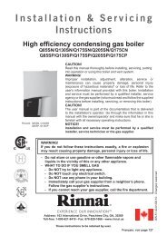
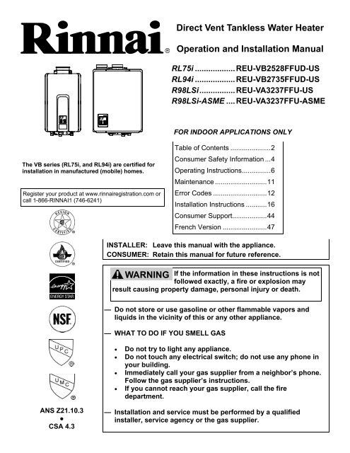
<strong>Direct</strong> <strong>Vent</strong> <strong>Tankless</strong> <strong>Water</strong> <strong>Heater</strong><br />
Operation and Installation Manual<br />
RL75i .................. REU-VB2528FFUD-US<br />
RL94i .................. REU-VB2735FFUD-US<br />
R98LSi ................ REU-VA3237FFU-US<br />
R98LSi-ASME .... REU-VA3237FFU-ASME<br />
FOR INDOOR APPLICATIONS ONLY<br />
Table of Contents ..................... 2<br />
Consumer Safety Information ... 4<br />
Operating Instructions ............... 6<br />
Maintenance ........................... 11<br />
Error Codes ............................ 12<br />
Installation Instructions ........... 16<br />
Consumer Support .................. 44<br />
French Version ....................... 47<br />
INSTALLER: Leave this manual with the appliance.<br />
CONSUMER: Retain this manual for future reference.<br />
WARNING If the information in these instructions is not<br />
followed exactly, a fire or explosion may<br />
result causing property damage, personal injury or death.<br />
• Do not try to light any appliance.<br />
• Do not touch any electrical switch; do not use any phone in<br />
your building.<br />
• Immediately call your gas supplier from a neighbor’s phone.<br />
Follow the gas supplier’s instructions.<br />
• If you cannot reach your gas supplier, call the fire<br />
department.<br />
— Installation and service must be performed by a qualified<br />
installer, service agency or the gas supplier.
R<br />
R98LSi-ASME<br />
Specifications ..................................................... 3<br />
Consumer Safety Information<br />
Safety Definitions ............................................. 4<br />
Safety Behaviors and Practices ....................... 4<br />
Safety Features................................................ 4<br />
Description of Operation .................................... 4<br />
Operating Instructions<br />
Temperature Controller .................................... 5<br />
Features Available on Temperature<br />
Controllers ........................................................ 6<br />
How to Set the Temperature ............................ 7<br />
Temperature Controller Settings .................. 7, 8<br />
Temperature Options Without<br />
a Temperature Controller ................................. 8<br />
Setting the Sound Volume (Voice Prompt) ...... 8<br />
Using the <strong>Water</strong> Smart / Bath Fill Function ..... 9<br />
Overview ..................................................... 9<br />
Setting the <strong>Water</strong> Volume ........................... 9<br />
Filling the Tub ............................................ 10<br />
Setting Controller to Mute .............................. 10<br />
Setting the Clock ............................................ 10<br />
Maintenance<br />
Cleaning .................................................... 11<br />
<strong>Vent</strong> System .............................................. 11<br />
Motors ....................................................... 11<br />
Temperature Controller ............................. 11<br />
Lime / Scale Build-up ................................ 11<br />
Snow Accumulation ................................... 11<br />
Visual Inspection of Flame ........................ 11<br />
Error Codes<br />
Error Code Table ...................................... 12,13<br />
Trouble Shooting for Common Issues ........... 14<br />
Accessing Operating Information................... 14<br />
<strong>Water</strong> Quality ................................................. 14<br />
Flushing the Heat Exchanger<br />
(Error Code: LC or 00) ................................... 15<br />
Installation Instructions ................................... 16<br />
General Instructions ....................................... 16<br />
Clearances from Appliance ............................ 17<br />
Attachment of the <strong>Water</strong> <strong>Heater</strong> .................... 17<br />
Electrical Connection ..................................... 18<br />
Error Indication or Air Handler Control Switch ...<br />
(RL75i, RL94i only) ........................................ 18<br />
Table of Contents<br />
2 VB Series Indoor LS Manual<br />
This model has been built in accordance with<br />
the requirements of the ASME Boiler and<br />
Pressure Vessel Code and has received the<br />
Certificate of Authorization from the National<br />
Board. The heat exchanger on this unit has<br />
the NB and HLW stamps.<br />
California Proposition 65 lists chemical substances known to the state to cause cancer, birth defects, death,<br />
serious illness or other reproductive harm. This product may contain such substances, be their origin from fuel<br />
combustion (gas, oil) or components of the product itself.<br />
Gas Piping<br />
General Instructions ................................ 18<br />
Pipe Sizing Procedure - Example ............ 19<br />
<strong>Water</strong> Piping<br />
Isolation Valves and<br />
Pressure Relief Valves ............................ 20<br />
Piping Requirements ............................... 21<br />
Pressure Relief Valve Requirements ...... 21<br />
Freeze Protection .............................. 21, 22<br />
Freeze Protection Piping ............................... 23<br />
Recommended Piping for Basic Installation .. 24<br />
Recommended Piping for<br />
Circulation Systems ....................................... 25<br />
<strong>Vent</strong>ing Instructions<br />
Intake / Exhaust Guidelines ..................... 26<br />
Condensate ............................................. 26<br />
Maximum <strong>Vent</strong> Length ............................ 27<br />
<strong>Vent</strong> Products .......................................... 28<br />
Flue Terminal Clearances<br />
(ANS Z21.10.3, CSA 4.3) .............................. 29<br />
Additional Clearances - <strong>Vent</strong> Terminal .......... 30<br />
Flue Installation - Concentric <strong>Vent</strong>ing<br />
(RL75i, RL94i) ................................................ 31<br />
Flue Installation<br />
(R98LSi, R98LSi-ASME).......................... 32, 33<br />
Connecting Multiple <strong>Water</strong> <strong>Heater</strong>s ............... 34<br />
High Altitude Installations ........................ 34, 35<br />
Temperature Controller Installation<br />
Location ................................................... 36<br />
Configurations.......................................... 36<br />
Cable Lengths and Size .......................... 36<br />
Mounting the Controller ........................... 37<br />
Operating Instructions ................................... 38<br />
Technical Data<br />
Pressure Drop Curve ..................................... 39<br />
Outlet Flow Data ............................................ 39<br />
Space Heating ............................................... 40<br />
Dimensions .................................................... 41<br />
Ladder Diagrams ..................................... 42, 43<br />
Consumer Support<br />
Warranty Information ..................................... 44<br />
Limited Warranty ...................................... 44, 45<br />
State Regulations .............................................. 46<br />
French Version ............................................ 47-68
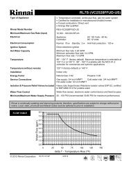
Specifications<br />
Model RL75i RL94i R98LSi R98LSi-ASME<br />
Minimum Gas Consumption Btu/h<br />
Maximum Gas Consumption Btu/h 180,000<br />
Hot water capacity (Min - Max) *<br />
Hot water capacity (45°F rise)<br />
0.4 - 7.5 GPM<br />
(1.5 - 28.5 L/min)<br />
6.6 GPM<br />
(25.0 L/min)<br />
9,900 (NG)<br />
10,300 (LPG)<br />
199,000 (NG)<br />
190,000 (LP)<br />
0.4 - 9.4 GPM<br />
(1.5 - 35.5 L/min)<br />
7.1 GPM<br />
(27.0 L/min)<br />
Default Temperature Setting (no controller) 120º F (49º C)<br />
Temperature Controller Default Setting 104º F (40º C)<br />
Maximum Temp Setting (commercial **) 160º F (71º C) 185º F (85º C)<br />
Maximum Temp Setting (residential)<br />
see Temperature Ranges for more information<br />
Selectable at 120º F (49º C) or at 140º F<br />
(60º C)<br />
Minimum Temperature Setting 98º F (37º C)<br />
<strong>Rinnai</strong> is continually updating and improving products. Therefore, specifications are subject to change without<br />
prior notice.<br />
The maximum inlet gas pressure must not exceed the value specified by the manufacturer. The minimum value<br />
listed is for the purpose of input adjustment.<br />
19,000<br />
237,000<br />
0.6 - 9.8 GPM<br />
(2.4 - 37 L/min)<br />
8.5 GPM<br />
(32.2 L/min)<br />
140º F (60º C)<br />
Weight 51 lb (23 kg) 53 lb (24 kg) 55 lb (25 kg)<br />
Efficiency Energy Factor: 0.82<br />
Thermal Efficiency: 84.0%<br />
Noise level 49 dB<br />
Electrical Consumption<br />
Normal 76 W 83 W 99 W<br />
Standby 2 W<br />
Anti-frost Protection 184 W 116 W<br />
By-Pass Control Fixed Electronic<br />
Minimum Gas Supply Natural Gas 5.0 inch W.C.<br />
Pressure<br />
Propane 8.0 inch W.C.<br />
Maximum Gas Supply Natural Gas 10.5 inch W.C.<br />
Pressure<br />
Propane 13.5 inch W.C.<br />
Type of Appliance <strong>Direct</strong> <strong>Vent</strong>, Temperature controlled continuous flow gas hot water system.<br />
Operation With or without remote controls, mounted in kitchen, bathroom, etc.<br />
Approved Gas Type Natural Gas or Propane - Ensure unit matches gas type supplied at the installation<br />
Connections Gas Supply: 3/4" MNPT, Cold <strong>Water</strong> Inlet: 3/4" MNPT, Hot <strong>Water</strong> Outlet: 3/4" MNPT<br />
Ignition System <strong>Direct</strong> Electronic Ignition<br />
Electric Connections Appliance: AC 120 Volts, 60Hz. Remote Control: DC 12 Volts (Digital)<br />
<strong>Water</strong> Temperature Control Simulation Feedforward and Feedback.<br />
<strong>Water</strong> Supply Pressure Minimum <strong>Water</strong> Pressure: 20 PSI (Recommended 30-80 PSI for maximum<br />
Maximum <strong>Water</strong> Supply Pressure 150 PSI<br />
Remote Control Cable Non-Polarized Two Core Cable (Minimum 22 AWG)<br />
Energy Star Qualified Yes Yes No (not applicable)<br />
Certified for installation in manufactured (mobile)<br />
homes<br />
Yes Yes No No<br />
* Minimum flow may vary slightly depending on the temperature setting and the inlet water temperature.<br />
** for commercial and hydronic applications requiring higher temperatures<br />
VB Series Indoor LS Manual 3
Safety Definitions<br />
This is the safety alert symbol. This symbol alerts you to potential hazards that can kill or hurt you and<br />
others.<br />
DANGER<br />
WARNING<br />
CAUTION<br />
Safety Behaviors and Practices<br />
WARNING<br />
Indicates an imminently hazardous situation which, if not avoided, will result in death or<br />
serious injury.<br />
Indicates a potentially hazardous situation which, if not avoided, could result in death or<br />
serious injury.<br />
Indicates a potentially hazardous situation which, if not avoided, could result in minor or<br />
moderate injury. It may also be used to alert against unsafe practices.<br />
• Keep the area around the appliance clear and free<br />
from combustible materials, gasoline, and other<br />
flammable vapors and liquids.<br />
• Any alteration to the appliance or its controls can be<br />
dangerous and will void the warranty.<br />
• Always check the water temperature before entering<br />
a shower or bath.<br />
Safety Features<br />
• Overheat: The appliance will automatically shut<br />
down when the appliance exceeds a predetermined<br />
temperature.<br />
• Flame Failure: The appliance will automatically<br />
shut down if the burner flame is not adequate.<br />
• Power Failure: The appliance will cut off the gas if<br />
it loses electrical power.<br />
The <strong>Rinnai</strong> water heater is one of the most advanced<br />
water heaters available. It provides a continuous<br />
supply of hot water at a preset temperature. This<br />
appliance is direct vent where air is brought in from the<br />
outside and combustion gases are exhausted to the<br />
outside.<br />
While electricity, water, and gas supplies are<br />
connected, the <strong>Rinnai</strong> water heater produces hot water<br />
whenever a hot water tap is open.<br />
Ignition is electronic. There is no pilot light consuming<br />
gas while the water heater is not being used. The gas<br />
burner lights automatically when the hot water tap is<br />
opened and goes out when the tap is closed.<br />
Consumer Safety Information<br />
Description of Operation<br />
4 VB Series Indoor LS Manual<br />
• Do not use this appliance if any part has been under<br />
water. Immediately call a qualified service<br />
technician to inspect the appliance and to replace<br />
any part of the control system and any gas control<br />
which has been under water.<br />
• Power Surge Fuse: A glass fuse protects against<br />
overcurrent. If the fuse blows then all indicator<br />
lamps will be off.<br />
• Fusible Link: In case the overheat feature does<br />
not prevent the temperature from rising then the<br />
fusible link will break shutting off the appliance.<br />
Installation of the temperature controller is highly<br />
recommended. The temperature controller can set the<br />
temperature within a specific range and can provide<br />
error codes to diagnose any problems.<br />
The temperature of the outgoing hot water is constantly<br />
monitored. The <strong>Rinnai</strong> water heater may adjust the<br />
water flow in order to maintain the temperature setting.<br />
The water flow may vary from summer to winter due to<br />
the difference in ground water temperature.
Temperature Controller<br />
Dimensions (inches): 3.5 W x 4.75 H x 0.75 D<br />
MC-91-1US & MCC-91-1US<br />
The MC-91 controller is the standard temperature controller that is supplied with the water heater. On indoor<br />
models it is integrated into the front panel. The MCC-91 controller is for commercial and hydronic applications<br />
requiring higher temperatures. When the MCC-91 controller is connected, these higher temperatures are<br />
available on all controller models in the system. Refer to the section on temperature ranges.<br />
In Use<br />
Indicator<br />
Temperature<br />
Display<br />
Temperature<br />
Selection<br />
Priority<br />
Indicator<br />
Priority<br />
Button<br />
ON/OFF<br />
Button<br />
VB Series Indoor LS Manual 5
Operating Instructions<br />
The MC-91 temperature controller is supplied with the RL75, RL94, and R98LS models. Additional functions are<br />
available through the use of optional controllers.<br />
There are several models of temperature controllers that can be purchased separately. Their description,<br />
operation, and installation is provided in this manual in case additional temperature controllers are purchased and<br />
installed.<br />
Features Available on Temperature Controllers<br />
Features<br />
MC-91<br />
MC-100<br />
6 VB Series Indoor LS Manual<br />
BC-100<br />
MC-502<br />
Description<br />
Call Sends a short series of beeps to all controllers in the system. It is<br />
not an intercom.<br />
Clock 12 hour AM/PM clock. (The MC-100 must be installed for clock<br />
to work on the BC-100.)<br />
Function Used on this model to set the clock or sound volume.<br />
In Use Indicator Indicates that hot water is being supplied (i.e. a hot water tap is<br />
open).<br />
ON/OFF Button Used to turn the water heater ON or OFF.<br />
Power Save Allows the temperature controller to be in an energy saving<br />
mode.<br />
Priority Button /<br />
Indicator<br />
Indicates that this controller is setting the temperature . Priority<br />
can be switched to another controller by pressing its Priority<br />
Button when no hot water is running.<br />
Sound Volume Used to adjust the voice prompt volume.<br />
Temperature Display Shows the temperature setting.<br />
Thermostat Increases or decreases the temperature setting.<br />
<strong>Water</strong> Smart / Bath Fill<br />
Button / Indicator<br />
MCC-91<br />
Error Codes When a fault is detected an error code flashes at the temperature<br />
display on models MC-91, MCC-91, and MC-502; and flashes at<br />
the clock display on models MC-100 and BC-100.<br />
Used to select the <strong>Water</strong> Smart / Bath Fill Function to fill a bath<br />
with a predetermined volume of water.<br />
<strong>Water</strong> Volume Used to select the water volume for the <strong>Water</strong> Smart / Bath Fill<br />
Function.
How to Set the Temperature<br />
DANGER<br />
Temperature Controller Settings<br />
Hot water can be dangerous, especially for infants or children, the elderly,<br />
or infirm. There is hot water scald potential if the thermostat is set too high.<br />
<strong>Water</strong> temperatures over 125º F (52º C) can cause severe burns or<br />
scalding resulting in death.<br />
Hot water can cause first degree burns with exposure for as little as:<br />
3 seconds at 140º F (60º C)<br />
20 seconds at 130º F (54º C)<br />
8 minutes at 120º F (49º C)<br />
Test the temperature of the water before placing a child in the bath or<br />
shower.<br />
Do not leave a child or an infirm person in the bath unsupervised.<br />
NOTICE<br />
While any hot water is being provided,<br />
the temperature setting can only be<br />
adjusted between 98º F and 110º F.<br />
This water heater will attempt to provide hot water at the temperature setting even when the water flow is varied<br />
or when more than 1 tap is in use. The water heater can deliver water at only one temperature setting at a time.<br />
The available temperatures for a given model are provided below.<br />
Model<br />
RL75i 98 100 102 104 106 108 110 115 120 125<br />
*<br />
R98LSi<br />
R98LSi-ASME<br />
1. If the water heater is off, press<br />
the ON/OFF button to turn on.<br />
2. Press the “Priority button” on the<br />
temperature controller. The<br />
green Priority light will glow<br />
indicating that this controller is<br />
controlling the temperature and<br />
that the <strong>Rinnai</strong> water heater is<br />
ready to supply hot water.<br />
The priority can only be changed<br />
while no hot water is running.<br />
3. Press the ▲ or ▼ buttons to<br />
obtain the desired temperature<br />
setting.<br />
All hot water sources are able to<br />
provide water at this temperature<br />
setting until it is changed again at<br />
this or another temperature<br />
controller.<br />
NOTICE<br />
NOTICE<br />
NOTICE<br />
Temperature Settings Available (ºF)<br />
RL94i 98 100 102 104 106 108 110 115 120 125<br />
*<br />
Check local codes for the maximum<br />
water temperature setting allowed<br />
when used in nursing homes, schools,<br />
day care centers, and all other public<br />
applications.<br />
If a newly installed unit with a<br />
controller has not been powered for at<br />
least 6 hours then the temperature will<br />
return to the default setting of 104º F<br />
(40º C) if power is interrupted.<br />
There may be a variation between the<br />
temperature displayed on the<br />
temperature controller and the<br />
temperature at the tap due to weather<br />
conditions or the length of pipe to the<br />
water heater.<br />
98 100 102 104 106 108 110 115 120 125 130 135 140 150<br />
**<br />
Temp in Celsius ºC 37 38 39 40 41 42 43 46 49 52 54 57 60 66 71 85<br />
An older controller, MC-45, can be installed with the RL75i and RL94i by moving switch No. 6 in the bank of 6<br />
switches to ON. Some of the temperature settings will be slightly different from the above table.<br />
130<br />
*<br />
130<br />
*<br />
135<br />
*<br />
135<br />
*<br />
140<br />
*<br />
140<br />
*<br />
150<br />
**<br />
150<br />
**<br />
160<br />
**<br />
160<br />
**<br />
160<br />
**<br />
185<br />
**<br />
185<br />
**<br />
VB Series Indoor LS Manual 7
Temperature Controller Settings<br />
* Re-setting the Maximum Temperature (RL75 and RL94 only)<br />
Models RL75 and RL94 have a default maximum temperature of 120º F<br />
(49º C) and an option to increase the maximum temperature to 140 ºF<br />
(60 ºC). Temperature settings from 125-140 ºF (52-60 ºC) are available<br />
by setting switch 6 to ON in the SW1 bank of 8 switches.<br />
** MCC-91 Temperature Controller<br />
These settings require the MCC-91 controller. When the MCC-91<br />
controller is connected, these higher temperatures are available on all<br />
controller models in the system. Use of an MCC-91 controller in a<br />
residential dwelling will reduce the warranty coverage to that of a<br />
commercial warranty application.<br />
The MCC-91 controller is intended for commercial and hydronic<br />
applications only. If an MCC-91 controller is used in a residential<br />
dwelling for a hydronics application, a mixing valve must also be<br />
installed to limit the potable hot water temperature to a safe<br />
temperature. <strong>Water</strong> temperatures over 125º F (52º C) can cause severe<br />
burns or scalding. Refer to the Danger Alert on water temperatures.<br />
<strong>Rinnai</strong> shall not, in any event, be liable for damages resulting from such<br />
misuse or misapplication.<br />
Suggested temperatures are<br />
• Kitchen 120 ºF (49º C)<br />
• Shower 98 - 110 ºF (37 - 43 ºC)<br />
• Bath Fill 102 - 110 ºF (39 - 43 ºC)<br />
These temperatures are suggestions only.<br />
Temperature Options Without a Temperature Controller<br />
8 VB Series Indoor LS Manual<br />
WARNING<br />
DO NOT adjust the other switches<br />
unless specifically instructed to do<br />
so.<br />
A temperature lower than 98º F (37º C) can be<br />
obtained at the tap by mixing with cold water.<br />
To change the temperature scale from Celsius to<br />
Fahrenheit or vice versa, press and hold the “On/Off”<br />
button for 5 seconds while the water heater is OFF.<br />
The default temperature setting for this appliance installed without a temperature controller is 120º F (49º C). If<br />
desired, the temperature setting can be changed to 140º F (60º C) by adjustment of a switch.<br />
In the SW1 bank of 8 switches, set switch 5 to ON to obtain 140º F water temperature setting. Set switch 5 to<br />
OFF (default) to obtain 120º F water temperature setting.<br />
If a temperature controller is installed, then switch 5 has no effect on temperature settings.<br />
Setting the Sound Volume (Voice Prompt)<br />
MC-100V Press the “Function” button to<br />
adjust the voice prompt<br />
volume. The default sound<br />
volume is set to Medium.<br />
Each subsequent press of the<br />
▲ or ▼ button cycles through<br />
the volume levels in the order<br />
below.<br />
Medium Volume<br />
(default)<br />
High Volume<br />
Off Volume<br />
(beep)<br />
O<br />
F<br />
F<br />
BC-100V Press the “Sound Vol.” button to<br />
adjust the voice prompt volume.<br />
The default sound volume is set<br />
to Medium. Each subsequent<br />
press of the button cycles<br />
through the volume levels in the<br />
order below.<br />
Off Sound<br />
(no beep)<br />
Maximum Temperature<br />
120º F (49º C) 140 ºF (60 ºC)<br />
Switch No.<br />
Switch No.<br />
ON<br />
1<br />
2<br />
3<br />
4<br />
5<br />
6<br />
7<br />
8<br />
O<br />
F<br />
F<br />
Low Volume<br />
ON<br />
1<br />
2<br />
3<br />
4<br />
5<br />
6<br />
7<br />
8
Using the <strong>Water</strong> Smart / Bath Fill Function<br />
Overview<br />
This function is exclusive to the BC-100V temperature<br />
controller. The bath fill function allows the consumer<br />
to fill a tub with a preset volume of water at a preset<br />
temperature. This is done by pressing the bath fill<br />
button on the BC-100V controller while no hot water is<br />
flowing and then opening only the hot water tap. The<br />
water heater will stop the hot water flow when the<br />
preset volume has been reached. The hot water tap<br />
should then be closed and the bath fill button pressed.<br />
The temperature settings for the bath fill function are<br />
limited to those in the table below.<br />
Bath Fill Temperature Settings<br />
Available<br />
ºF 98 100 102 104 106 108<br />
ºC 37 38 39 40 41 42<br />
ºF 110 112 114 116 118 120<br />
ºC 43 44 46 47 48 49<br />
Setting the <strong>Water</strong> Volume<br />
The default volume is set to 25 gallons. The volume<br />
can be set between 10 and 120 gallons.<br />
1. Press the “Priority” button on the<br />
temperature controller. The green<br />
Priority light will glow indicating<br />
that this controller is controlling<br />
the temperature and that the<br />
<strong>Rinnai</strong> water heater is ready to<br />
supply hot water.<br />
2. Press the “<strong>Water</strong> Smart Bath Fill”<br />
button to set the water volume<br />
and temperature.<br />
3. Press the “Temp” ▲ or ▼ buttons<br />
to obtain the desired temperature<br />
setting.<br />
NOTICE<br />
Multiple<br />
<strong>Water</strong><br />
<strong>Heater</strong>s<br />
NOTICE<br />
Power<br />
Loss<br />
NOTICE<br />
Anti-scald<br />
Fixtures<br />
NOTICE<br />
To Prevent<br />
Over Filling<br />
The bath fill function will not work<br />
properly if it is connected to multiple<br />
water heaters. The tub will overfill<br />
because the bath fill function is not<br />
able to measure the water volume<br />
when connected to multiple water<br />
heaters.<br />
If power is lost during the bath fill<br />
function, the water heater will shut<br />
down but the water will continue to<br />
flow. When power returns, the water<br />
shuts off and Error Code 03 appears<br />
on the controller.<br />
If power is lost after the bath has filled<br />
but before the bath fill function button<br />
is de-selected, then the water will not<br />
flow during the power loss or after the<br />
power is returned. Once power<br />
returns, close the hot water tap and<br />
de-select the bath fill function. No<br />
error code appears.<br />
Do not use with single handle fixtures<br />
that have anti-scald features built into<br />
them. These fixtures allow a<br />
predetermined amount of cold water<br />
which is not taken into account by the<br />
bath fill function.<br />
4. Press the “<strong>Water</strong> Vol.”▲ or ▼<br />
buttons to obtain the desired<br />
water volume in gallons.<br />
5. Press the “<strong>Water</strong> Smart Bath Fill”<br />
button.<br />
Be careful not to overfill the bath. An<br />
average bath volume is 60 gallons.<br />
When filling the bath using this<br />
function for the first time:<br />
•Monitor and remain by the bath while<br />
the water is running.<br />
•Use a low bath fill volume less than<br />
25 gallons<br />
VB Series Indoor LS Manual 9
Using the <strong>Water</strong> Smart / Bath Fill Function<br />
Filling the Tub<br />
1. Press the “<strong>Water</strong> Smart / Bath Fill”<br />
button once. The button will<br />
illuminate, and a tone will sound.<br />
2. The voice prompt will announce<br />
“The hot water system is ready.<br />
Open the hot water tap.”<br />
ON! COLD Make sure the water volume is set.<br />
Refer to “Setting the <strong>Water</strong><br />
Volume” on the previous page.<br />
Open the hot water tap. The “In<br />
HOT<br />
Use” indicator will illuminate on<br />
MC-100V and BC-100V controllers.<br />
The hot water will begin to flow.<br />
ON! COLD 3. When the preset volume of water<br />
has been produced then<br />
HOT<br />
Setting Controller to Mute<br />
Models MC-91 and MCC-91<br />
To eliminate the beeps when keys are pressed or to turn the beeps back on, press and hold both the ▲and ▼<br />
buttons until a beep is heard (approximately 5 seconds).<br />
Setting the Clock<br />
•the water flow will cease<br />
•the “<strong>Water</strong> Smart / Bath Fill”<br />
button will flash<br />
•a tone will sound<br />
•the voice prompt will announce,<br />
“Bath fill is complete. Turn<br />
off the bath hot water tap and<br />
push the Bath Fill button.”<br />
4. Turn off the bath hot water tap and<br />
push the Bath Fill button. The<br />
water heater will not allow hot<br />
water to flow from any source until<br />
the “<strong>Water</strong> Smart / Bath Fill” button<br />
is pushed.<br />
The button light will go out.<br />
NOTICE<br />
To Stop the<br />
Bath Fill<br />
Before it<br />
Finishes<br />
NOTICE<br />
When<br />
Other Taps<br />
Are Open<br />
NOTICE<br />
MC-100V Press the “Function” button twice within 10 seconds to set the clock. Press the ▲ or<br />
▼ button to reach the desired time. The clock on the BC-100V automatically shows<br />
the time which has been set on the MC-100V.<br />
10 VB Series Indoor LS Manual<br />
To stop the water flow during the Bath<br />
Fill function, press the “<strong>Water</strong> Smart /<br />
Bath Fill” button. The button will flash<br />
and the voice prompt will announce,<br />
“Hot water is not available. Turn off<br />
all hot water taps and push the Bath<br />
Fill button.” Follow the voice prompt<br />
instructions.<br />
During the bath fill function, any hot<br />
water flowing at other locations,<br />
subtracts from the total amount of<br />
water for the bath. For example if the<br />
bath fill function is set for 50 gallons<br />
and 5 gallons of hot water are used at<br />
other locations during the fill period<br />
then the bath will only fill with 45<br />
gallons.<br />
During the operation of the bath fill<br />
function, the MC-91 “In Use” indicator<br />
does not light up.
Maintenance<br />
WARNING<br />
Turn off the electrical power supply, the manual gas<br />
valve and the manual water control valve whenever<br />
servicing the unit.<br />
Repairs and maintenance should be performed by a<br />
qualified service technician. The appliance should be<br />
inspected annually by a qualified service technician.<br />
Verify proper operation after servicing.<br />
Cleaning<br />
It is imperative that control compartments, burners,<br />
and circulating air passageways of the appliance be<br />
kept clean.<br />
Clean as follows:<br />
1. Turn off and disconnect electrical power. Allow to<br />
cool.<br />
2. Close the water shut off valves. Remove and clean<br />
the water inlet filter.<br />
3. Remove the front panel by removing 4 screws.<br />
4. Use pressurized air to remove dust from the main<br />
burner, heat exchanger, and fan blades. Do not<br />
use a wet cloth or spray cleaners on the burner.<br />
Do not use volatile substances such as benzene<br />
and thinners. They may ignite or fade the paint.<br />
5. Use soft dry cloth to wipe cabinet.<br />
<strong>Vent</strong> System<br />
The vent system should be inspected at least annually<br />
for blockages or damage.<br />
Motors<br />
Motors are permanently lubricated and do not need<br />
periodic lubrication. Keep fan and motor free of dust<br />
and dirt by cleaning annually.<br />
Temperature Controller<br />
Use a soft damp cloth to clean the temperature<br />
controller. Do not use solvents.<br />
Lime / Scale Build-up<br />
If you receive Error Code “LC”, refer to the procedure,<br />
Flushing the Heat Exchanger. Refer to the section on<br />
<strong>Water</strong> Quality to see if your water needs to be treated<br />
or conditioned. (When checking maintenance code<br />
history, “00” is substituted for “LC”.)<br />
Snow Accumulation<br />
Keep the area around flue terminal free of snow and<br />
ice. The appliance will not function properly if the<br />
intake air or exhaust is impeded (blocked or partially<br />
blocked) by obstructions.<br />
Visual Inspection of Flame<br />
The burner must flame evenly over the entire surface<br />
when operating correctly. The flame must burn with a<br />
clear, blue, stable flame. See the parts breakdown of<br />
the burner for the location of the view ports.<br />
The flame pattern should be as shown in the figures<br />
below.<br />
VB Series Indoor LS Manual 11
Error Codes<br />
The <strong>Rinnai</strong> water heater has the ability to check its own operation continuously. If a fault occurs, an error code<br />
will flash on the display of the temperature controller. This assists with diagnosing the fault and may enable you<br />
to overcome a problem without a service call. Please identify the code displayed when inquiring about service.<br />
WARNING<br />
Code Fault Remedy<br />
02 No burner operation during<br />
freeze protection mode<br />
Service Call<br />
03 Power interruption during<br />
Bath Fill (<strong>Water</strong> will not flow<br />
when power returns).<br />
10 Air Supply or Exhaust<br />
Blockage<br />
Some of the checks below may need to be done by a qualified service technician. Call a<br />
service technician for any remedy that involves gas or electricity. Call a service<br />
technician if you have any doubt or reservation about performing the remedy yourself.<br />
Turn off all hot water taps. Press ON/OFF twice.<br />
Ensure <strong>Rinnai</strong> approved venting materials are being used.<br />
Check that nothing is blocking the flue inlet or exhaust.<br />
Check all vent components for proper connections.<br />
Ensure vent length is within limits.<br />
Ensure condensation collar was installed correctly.<br />
Verify dip switches are set properly.<br />
Check fan for blockage.<br />
11 No Ignition Check that the gas is turned on at the water heater, gas meter, or cylinder.<br />
Ensure gas type and pressure is correct.<br />
Ensure gas line, meter, and/or regulator is sized properly.<br />
Bleed all air from gas lines.<br />
Verify dip switches are set properly.<br />
Ensure appliance is properly grounded.<br />
Disconnect EZConnect or MSA controls to isolate the problem.<br />
Ensure igniter is operational.<br />
Check igniter wiring harness for damage.<br />
Check gas solenoid valves for open or short circuits.<br />
Remove burner cover and ensure all burners are properly seated.<br />
Remove burner plate and inspect burner surface for condensation or debris.<br />
12 Flame Failure Check that the gas is turned on at the water heater and gas meter. Check for<br />
obstructions in the flue outlet.<br />
Ensure gas line, meter, and/or regulator is sized properly.<br />
Ensure gas type and pressure is correct.<br />
Bleed all air from gas lines.<br />
Ensure proper <strong>Rinnai</strong> venting material was installed.<br />
Ensure condensation collar was installed properly.<br />
Ensure vent length is within limits.<br />
Verify dip switches are set properly.<br />
Ensure appliance is properly grounded.<br />
Disconnect keypad.<br />
Disconnect EZConnect or MSA controls to isolate the problem.<br />
Check power supply for loose connections.<br />
Check power supply for proper voltage and voltage drops.<br />
Ensure flame rod wire is connected.<br />
Check flame rod for carbon build-up.<br />
Disconnect and reconnect all wiring harnesses on unit and PC board.<br />
Check for DC shorts at components.<br />
Check gas solenoid valves for open or short circuits.<br />
Remove burner plate and inspect burner surface for condensation or debris.<br />
Check the ground wire for the PC board.<br />
12 VB Series Indoor LS Manual
Code Fault Remedy<br />
16 Over Temperature<br />
Warning<br />
31 Burner Sensor Error Measure resistance of sensor.<br />
32 Outgoing <strong>Water</strong><br />
Temperature Sensor<br />
Fault<br />
33 Heat Exchanger<br />
Outgoing Temperature<br />
Sensor Fault<br />
34 Combustion Air<br />
Temperature Sensor<br />
Fault<br />
Error Codes<br />
14 Thermal Fuse Check gas type of unit and ensure it matches gas type being used.<br />
Check for restrictions in air flow around unit and vent terminal.<br />
Check for low water flow in a circulating system causing short-cycling.<br />
Ensure dip switches are set to the proper position.<br />
Check for foreign materials in combustion chamber and/or exhaust piping.<br />
Check heat exchanger for cracks and/or separations.<br />
Check heat exchanger surface for hot spots which indicate blockage due to scale build-up.<br />
Refer to instructions in manual for flushing heat exchanger.<br />
Measure resistance of safety circuit.<br />
Ensure high fire and low fire manifold pressure is correct.<br />
Check for improper conversion of product.<br />
Check for restrictions in air flow around unit and vent terminal.<br />
Check for low water flow in a circulating system causing short-cycling.<br />
Check for foreign materials in combustion chamber and/or exhaust piping.<br />
Check for clogged heat exchanger.<br />
Replace sensor.<br />
Check sensor wiring for damage.<br />
Measure resistance of sensor.<br />
Clean sensor of scale build-up.<br />
Replace sensor.<br />
Check sensor wiring for damage.<br />
Measure resistance of sensor.<br />
Clean sensor of scale build-up.<br />
Replace sensor.<br />
Check for restrictions in air flow around unit and vent terminal.<br />
Check sensor wiring for damage.<br />
Measure resistance of sensor.<br />
Clean sensor of scale build-up.<br />
Ensure fan blade is tight on motor shaft and is in good condition.<br />
Replace sensor.<br />
Check modulating gas solenoid valve wiring harness for loose or damaged terminals.<br />
Measure resistance of valve coil.<br />
52 Modulating Solenoid<br />
Valve Signal Abnormal<br />
61 Combustion Fan Failure Ensure fan will turn freely.<br />
Check wiring harness to motor for damaged and/or loose connections.<br />
Measure resistance of motor winding.<br />
65 <strong>Water</strong> Flow Control Fault The water flow control valve has failed to close during the bath fill function. Immediately turn<br />
off the water and discontinue the bath fill function. Contact a state qualified or licensed<br />
contractor to service the appliance.<br />
71 Solenoid Valve Circuit<br />
Fault<br />
Replace the PC Board.<br />
72 Flame Sensing Device Ensure flame rod is touching flame when unit fires.<br />
Fault<br />
Check all wiring to flame rod for damage.<br />
Remove flame rod and check for carbon build-up; clean with sand paper.<br />
Check inside burner chamber for any foreign material blocking flame at flame rod.<br />
Measure micro amp output of sensor circuit with flame present.<br />
Replace flame rod.<br />
73 Burner Sensor Circuit Check sensor wiring and PC board for damage.<br />
Error<br />
Replace sensor.<br />
LC Scale Build-up in Heat Flush heat exchanger. Refer to instructions in manual.<br />
Exchanger (when Replace heat exchanger.<br />
checking maintenance NOTE: The LC code is the only error code that will allow the unit to keep running. The<br />
code history, “00” is display will alternate between the LC code and the temperature setting. The controller will<br />
substituted for “LC”) continue to beep. The LC code will reset if power is turned off and then on.<br />
No Nothing happens when Clean inlet water supply filter.<br />
code water flow is activated. On new installations ensure hot and cold water lines are not reversed.<br />
Check for bleed over. Isolate unit from building by turning off cold water line to building.<br />
Isolate the circulating system if present. Open your pressure relief valve; if water is<br />
flowing, there is bleed over in your plumbing.<br />
Ensure you have at least the minimum flow rate required to fire unit.<br />
Ensure turbine spins freely.<br />
Measure the resistance of the water flow control sensor.<br />
Check for DC shorts at components.<br />
VB Series Indoor LS Manual 13
Trouble Shooting for Common Issues<br />
I don’t have any hot water when I open the tap.<br />
Make sure there is gas, water, and electricity to the<br />
<strong>Rinnai</strong> water heater (power is turned on and the gas is<br />
turned on).<br />
When I was using the hot water, the water got cold.<br />
If you adjusted the flow from the tap to lessen it, you<br />
may have gone below the minimum flow required. The<br />
<strong>Rinnai</strong> water heater requires a minimum flow rate to<br />
operate. (See the specification page for the flow rate<br />
of your model.)<br />
If you are experiencing issues with higher temperature<br />
settings, then <strong>Rinnai</strong> recommends reducing the<br />
temperature setting. Selecting a temperature closer to<br />
that which is actually used at the faucet will increase<br />
the amount of hot water being delivered to the faucet,<br />
due to less cold water mixing at the fixture.<br />
Accessing Operating Information<br />
Models MC-91 and MCC-91<br />
Consideration of care for your water heater should<br />
include evaluation of water quality. If the water quality<br />
exceeds the target levels provided in the table, you<br />
may want to treat or condition the water.<br />
* Source: Part 143 National Secondary Drinking <strong>Water</strong><br />
Regulations<br />
14 VB Series Indoor LS Manual<br />
White smoke comes out of the exhaust.<br />
During colder weather when the exhaust temperature<br />
is much hotter than the outside air, the exhaust fumes<br />
condense producing water vapor.<br />
When I open a hot tap, I do not immediately get hot<br />
water.<br />
Hot water must travel through your plumbing from the<br />
<strong>Rinnai</strong> water heater to the faucet. The time period for<br />
hot water to reach your fixture is determined by the<br />
amount of water in the plumbing system between the<br />
water heater and the fixture, water pressure, and the<br />
flow rate of the fixture.<br />
After I turn off the hot water tap, the fan on the<br />
<strong>Rinnai</strong> water heater continues to run.<br />
The fan is designed to continue running for a short time<br />
after the flow of water stops. This is to ensure constant<br />
water temperatures during rapid starting and stopping,<br />
as well as exhausting any residual gas flue products<br />
from the unit.<br />
To display the most recent error codes press and hold the “On/Off” button for 2 seconds. While holding the “On/<br />
Off” button press the ▲ button. The last 9 error codes will flash one after the other. To exit this mode press the<br />
“On/Off” and ▲ button as before.<br />
To display the water flow through the water heater press and hold the ▲ button for 2 seconds and without<br />
releasing the ▲ button press the “On/Off” button.<br />
To display the outlet water temperature press and hold the ▼ button for 2 seconds and without releasing the ▼<br />
button press the “On/Off” button.<br />
<strong>Water</strong> Quality<br />
Maximum Level<br />
Total Hardness Up to 200 mg / L<br />
Aluminum * Up to 0.2 mg / L<br />
Chlorides * Up to 250 mg / L<br />
Copper * Up to 1.0 mg / L<br />
Iron * Up to 0.3 mg / L<br />
Manganese * Up to 0.05 mg / L<br />
pH * 6.5 to 8.5<br />
TDS (Total Dissolved<br />
Solids) *<br />
Up to 500 mg / L<br />
Zinc * Up to 5 mg / L
Flushing the Heat Exchanger (Error Code: LC or 00)<br />
An “LC” or “00” error code indicates the unit is beginning to lime up and must be flushed. Failure to flush the<br />
appliance will cause damage to the heat exchanger. Damage caused by lime build-up is not covered by the unit’s<br />
warranty. After flushing, reset the LC fault code by turning off the power to the unit and turning the power back<br />
on.<br />
1. Disconnect electrical power to the water heater.<br />
2. Close the shutoff valves on both the hot water and<br />
cold water lines (V3 and V4).<br />
3. Connect pump outlet hose (H1) to the cold water<br />
line at service valve (V2).<br />
4. Connect drain hose (H3) to service valve (V1).<br />
5. Pour 4 gallons of undiluted virgin, food grade,<br />
white vinegar into pail.<br />
6. Place the drain hose (H3) and the hose (H2) to<br />
the pump inlet into the cleaning solution.<br />
7. Open both service valves (V1 and V2) on the hot<br />
water and cold water lines.<br />
8. Operate the pump and allow the cleaning solution<br />
to circulate through the water heater for 1 hour at<br />
a rate of 4 gallons per minute (15.1 liters per<br />
minute).<br />
9. Turn off the pump.<br />
10. Rinse the cleaning solution from the water heater<br />
as follows:<br />
a. Remove the free end of the drain hose (H3)<br />
from the pail.<br />
b. Close service valve, (V2), and open shutoff<br />
valve, (V4). Do not open shutoff valve, (V3).<br />
c. Allow water to flow through the water heater for<br />
5 minutes<br />
d. Close service valve, (V1), and open shutoff<br />
valve, (V3).<br />
11. Disconnect all hoses.<br />
12. With (V4) closed, remove the in-line filter at the<br />
cold water inlet and clean out any residue. Place<br />
filter back into unit and open (V4).<br />
13. Restore electrical power to the water heater.<br />
CLEAN THERMISTORS<br />
Remove and clean thermistors<br />
with a soft cloth or sponge after<br />
removing O-rings.<br />
Cleaning solution is 4 gallons of<br />
undiluted virgin, food grade,<br />
white vinegar.<br />
H3<br />
H2<br />
3/4" Ball Valve<br />
3/4" Union<br />
Check Valve<br />
KEY<br />
Pressure Relief Valve<br />
V1<br />
V3<br />
Hot<br />
<strong>Water</strong><br />
Line<br />
Circulating Pump<br />
<strong>Water</strong> <strong>Heater</strong><br />
V2<br />
H1<br />
VB Series Indoor LS Manual 15<br />
S<br />
<strong>Rinnai</strong><br />
In-line<br />
Filter<br />
Pressure Regulator<br />
Circulating Pump<br />
Boiler Drain Valve<br />
Solenoid Valve<br />
V4<br />
Cold<br />
<strong>Water</strong><br />
Line<br />
Gas<br />
Supply
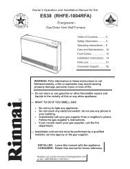
Only properly trained and qualified installers<br />
should install this appliance. The warranty may<br />
be voided due to improper installation or<br />
installation by a non-qualified installer.<br />
<strong>Rinnai</strong> highly recommends all installers attend a<br />
product knowledge class.<br />
For information on a <strong>Rinnai</strong> Training Course or<br />
for questions on installation call 1-800-621-<br />
9419.<br />
General Instructions<br />
WARNING<br />
Do not use substitute materials.<br />
Use only parts certified with the appliance.<br />
• This appliance must be installed by a state qualified<br />
or licensed contractor. It is the responsibility of the<br />
person having the water heater installed to ensure<br />
the installing contractor has proper licenses and<br />
permits for installing water heaters in your location.<br />
<strong>Rinnai</strong> highly recommends that installers attend a<br />
product knowledge class to ensure customer<br />
satisfaction and warranty coverage. Failure to<br />
comply with state and local codes pertaining to<br />
water heater installations may void the warranty.<br />
• This appliance is not to be installed outdoors.<br />
• A qualified installer or service technician should<br />
install the appliance, inspect it, and leak test it<br />
before use.<br />
• The installation must conform with local codes or, in<br />
the absence of local codes, with the National Fuel<br />
Gas Code, ANSI Z223.1/NFPA 54, or the Natural<br />
Gas and Propane Installation Code, CSA B149.1. If<br />
installed in a manufactured home, the installation<br />
must conform with the Manufactured Home<br />
Construction and Safety Standard, Title 24 CFR,<br />
Part 3280 and/or CAN/SCA Z240 MH Series, Mobile<br />
Homes.<br />
• The appliance, when installed, must be electrically<br />
grounded in accordance with local codes or, in the<br />
absence of local codes, with the National Electrical<br />
Code, ANSI/NFPA 70, or the Canadian Electrical<br />
Code, CSA C22.1.<br />
• The appliance and its appliance main gas valve<br />
must be disconnected from the gas supply piping<br />
system during any pressure testing of that system at<br />
test pressures in excess of 1/2 psi (3.5 kPa) (13.84<br />
in W.C.).<br />
Installation Instructions<br />
16 VB Series Indoor LS Manual<br />
RL75i .................. REU-VB2528FFUD-US<br />
RL94i .................. REU-VB2735FFUD-US<br />
R98LSi ................ REU-VA3237FFU-US<br />
R98LSi-ASME .... REU-VA3237FFU-ASME<br />
The VB series (RL75i, and RL94i) are certified for installation in<br />
manufactured (mobile) homes.<br />
• The appliance must be isolated from the gas supply<br />
piping system by closing its individual manual<br />
shutoff valve during any pressure testing of the gas<br />
supply piping system at test pressures equal to or<br />
less than 1/2 psi (3.5 kPa) (13.84 in W.C.).<br />
• Follow the installation instructions and those in Care<br />
and Maintenance for adequate combustion and<br />
ventilation air.<br />
• The appliance should be located in an area where<br />
water leakage of the unit or connections will not<br />
result in damage to the area adjacent to the<br />
appliance or to lower floors of the structure. When<br />
such locations cannot be avoided, it is<br />
recommended that a suitable drain pan, adequately<br />
drained, be installed under the appliance. The pan<br />
must not restrict combustion air flow.<br />
• The flow of combustion and ventilation air shall not<br />
be obstructed. Combustion air shall not be supplied<br />
from occupied spaces.<br />
• This appliance is not suitable for use in an<br />
application such as a pool or spa heater that uses<br />
chemically treated water . (This appliance is<br />
suitable for filling large or whirlpool bath tubs with<br />
potable water.)<br />
• If a water heater is installed in a closed water supply<br />
system, such as one having a backflow preventer in<br />
the cold water supply line, means shall be provided<br />
to control thermal expansion. Contact the water<br />
supplier or local plumbing inspector on how to<br />
control thermal expansion.<br />
• Should overheating occur or the gas supply fail to<br />
shut off, turn off the manual gas control valve to the<br />
appliance.<br />
• Keep the air intake location free of chemicals such<br />
as chlorine or bleach that produce fumes. These<br />
fumes can damage components and reduce the life<br />
of your appliance.<br />
• For gas type conversion, contact <strong>Rinnai</strong>.
Clearances from Appliance<br />
Top of<br />
<strong>Heater</strong><br />
Back of<br />
<strong>Heater</strong><br />
Front of<br />
<strong>Heater</strong><br />
Sides of<br />
<strong>Heater</strong><br />
Ground/<br />
Bottom<br />
<strong>Vent</strong><br />
to Combustibles<br />
RL75i<br />
RL94i<br />
6 inches **<br />
(152 mm)<br />
R98LSi<br />
12 inches<br />
(305 mm)<br />
Attachment of the <strong>Water</strong> <strong>Heater</strong><br />
to Non-<br />
Combustibles<br />
RL75i<br />
RL94i<br />
2 inches **<br />
(51 mm)<br />
1. Identify the installation location and confirm that<br />
the installation will meet all required clearances.<br />
2. Securely attach the water heater to the wall using<br />
any of the holes in the wall installation brackets<br />
which are at the top and bottom of the water<br />
heater. Ensure that the attachment strength is<br />
sufficient to support the weight. Refer to the<br />
weight of the water heater in the Specifications<br />
section.<br />
NOTE: <strong>Rinnai</strong> water heaters should be installed in an<br />
upright position. Do not install upside down or on its<br />
side.<br />
R98LSi<br />
2 inches<br />
(51 mm)<br />
0 (zero) 0 (zero) 0 (zero) 0 (zero)<br />
6 inches<br />
(152 mm)<br />
2 inches<br />
(51 mm)<br />
12 inches<br />
(305 mm)<br />
6 inches<br />
(152 mm)<br />
2 inches<br />
(51 mm)<br />
12 inches<br />
(305 mm)<br />
6 inches<br />
(152 mm)<br />
1/2 inch<br />
(13 mm)<br />
12 inches<br />
(305 mm)<br />
6 inches<br />
(152 mm)<br />
1/2 inch<br />
(13 mm)<br />
2 inches<br />
(51 mm)<br />
0 (zero) 4 inches * 0 (zero) 0 (zero)<br />
* 4 inches (102 mm) for enclosed area; 1 inch (26 mm) for unenclosed area.<br />
** 0 inches from vent components and condensate drain line.<br />
The clearance for servicing is 24 inches in front of the water heater.<br />
For closet installation: clearance is 6 inches (152 mm) from the front.<br />
to side<br />
to top<br />
to ground/bottom<br />
to front<br />
wall installation<br />
brackets<br />
VB Series Indoor LS Manual 17
Electrical Connection<br />
The water heater requires 120 VAC, 60 Hz power from a properly grounded circuit.<br />
If using the 6 foot long power cord, plug it into a standard 3 prong 120 VAC, 60 Hz properly grounded wall outlet.<br />
The wiring diagram is located on the Technical Sheet attached to the inside of the front cover.<br />
The water heater must be electrically grounded in accordance with local codes, or in the absence of local codes<br />
with the National Electrical Code, ANSI/NFPA 70 and/or the CSA C22.1, Canadian Electrical Code.<br />
Error Indication or Air Handler Control Switch (RL75i, and RL94i only)<br />
When using the <strong>Rinnai</strong> water heater with an Error Indication Switch, switch No. 4 in the bank of 8 switches should<br />
be in the off position. This is the default position.<br />
To connect the water heater to the <strong>Rinnai</strong> Air Handler, the Control Switch is necessary to function as the electrical<br />
connection. When the Control Switch is functioning as the electrical connection between the water heater and air<br />
handler, switch No. 4 in the bank of 8 switches should be in the on position.<br />
The Error Indication Switch and the <strong>Rinnai</strong> Air Handler Control Switch are optional products available from <strong>Rinnai</strong>.<br />
Installation instructions are included with these products.<br />
Gas Piping<br />
General Instructions<br />
• A manual gas control valve must be placed in the<br />
gas supply line to the <strong>Rinnai</strong> water heater. A union<br />
can be used on the connection above the shut off<br />
valve for the future servicing or disconnection of the<br />
unit.<br />
• Check the type of gas and the gas inlet pressure<br />
before connecting the <strong>Rinnai</strong> water heater. If the<br />
<strong>Rinnai</strong> water heater is not of the gas type that the<br />
building is supplied with, DO NOT connect the water<br />
heater. Contact the dealer for the proper unit to<br />
match the gas type.<br />
• Check the gas supply pressure immediately<br />
upstream at a location provided by the gas<br />
company. Supplied gas pressure must be within the<br />
limits shown in the Specifications section.<br />
• Before placing the appliance in operation all joints<br />
including the heater must be checked for gas<br />
tightness by means of leak detector solution, soap<br />
and water, or an equivalent nonflammable solution,<br />
as applicable. (Since some leak test solutions,<br />
18 VB Series Indoor LS Manual<br />
including soap and water, may cause corrosion or<br />
stress cracking, the piping shall be rinsed with water<br />
after testing, unless it has been determined that the<br />
leak test solution is non-corrosive.)<br />
• Always use approved connectors to connect the unit<br />
to the gas line. Always purge the gas line of any<br />
debris before connection to the water heater.<br />
• The gas supply line shall be gas tight, sized, and so<br />
installed as to provide a supply of gas sufficient to<br />
meet the maximum demand of the heater and all<br />
other gas consuming appliances at the location<br />
without loss of pressure.<br />
• Any compound used on the threaded joint of the gas<br />
piping shall be a type which resists the action of<br />
liquefied petroleum gas (propane / LPG).<br />
• Refer to an approved pipe sizing chart if in doubt<br />
about the size of the gas line.
Gas Piping<br />
Pipe Sizing Procedure - Example<br />
The gas supply must be capable of handling the entire gas load at the location. Gas line sizing is based on gas<br />
type, the pressure drop in the system, the gas pressure supplied, and gas line type. For gas pipe sizing in the<br />
United States, refer to the National Fuel Gas Code, NFPA 54. For Canadian gas pipe sizing, refer to the Natural<br />
Gas and Propane Installation Code CAN/CSA B149.1. The below information is provided as an example. The<br />
appropriate table from the applicable code must be used.<br />
1. For some tables, you will need to determine the cubic feet per hour of gas required by dividing the gas input<br />
by the heating value of the gas (available from the local gas company). The gas input needs to include all gas<br />
products at the location and the maximum BTU usage at full load when all gas products are in use.<br />
Gas Input of all gas products (BTU / HR)<br />
Cubic Feet per Hour (CFH) =<br />
Heating Value of Gas (BTU / FT 3 )<br />
2. Use the table for your gas type and pipe type to find the pipe size required. The pipe size must be able to<br />
provide the required cubic feet per hour of gas or the required BTU/hour.<br />
Example: The heating value of natural gas for your location is 1000 BTU/FT 3 . The gas input of the RL94i is<br />
199,000 BTU/HR. Additional appliances at the location require 65,000 BTU/hr. Therefore the cubic<br />
feet per hour = (199,000 + 65,000) / 1000 = 264 FT 3 /HR. If the pipe length is 10 feet then the 3/4 inch<br />
pipe size is capable of supplying 264 FT 3 /HR of natural gas.<br />
Pipe Sizing Table - Natural Gas Pipe Sizing Table - Propane Gas<br />
Schedule 40 Metallic Pipe<br />
Inlet Pressure: less than 2 psi (55 inches W.C.)<br />
Pressure Drop: 0.3 inches W.C.<br />
Specific Gravity: 0.60<br />
Capacity in cubic feet per hour<br />
Schedule 40 Metallic Pipe<br />
Inlet Pressure: 11.0 inches W.C.<br />
Pressure Drop: 0.5 inches W.C.<br />
Specific Gravity: 1.50<br />
Capacity in Thousands of BTU per Hour<br />
Length<br />
3/4<br />
Pipe Size (inches)<br />
1 1 1/4 1 1/2<br />
Length<br />
1/2<br />
Pipe Size (inches)<br />
3/4 1 1 1/4<br />
10 273 514 1060 1580 10 291 608 1150 2350<br />
20 188 353 726 1090 20 200 418 787 1620<br />
30 151 284 583 873<br />
30 160 336 632 1300<br />
40 129 243 499 747<br />
40 137 287 541 1110<br />
50 114 215 442 662<br />
50 122 255 480 985<br />
60 104 195 400 600<br />
60 110 231 434 892<br />
70 95 179 368 552<br />
80 101 212 400 821<br />
80 89 167 343 514 100 94 197 372 763<br />
90 83 157 322 482 125 89 185 349 716<br />
100 79 148 304 455 150 84 175 330 677<br />
125 70 131 269 403 175 74 155 292 600<br />
150 63 119 244 366 200 67 140 265 543<br />
175 58 109 224 336<br />
200 54 102 209 313<br />
VB Series Indoor LS Manual 19
<strong>Water</strong> Piping<br />
Isolation Valves and Pressure Relief Valve (RL75i and RL94i)<br />
The isolation valves provide the ability to isolate the<br />
water heater from the structure’s plumbing and allow<br />
quick access to flush the heat exchanger. Check with<br />
local codes to determine if a pressure and temperature<br />
relief valve is required. The included valves meet<br />
American National Standard (ANSI Z21.10.3) /<br />
Canadian Standard (CSA 4.3) and are ANSI/NSF 61<br />
approved for potable water.<br />
Isolation Valve (Cold) 107000081<br />
Isolation Valve (Hot) 107000083<br />
Pressure Relief Valve (PRV) 107000085<br />
Isolation Valves Installation Instructions:<br />
1. Wrap the ends of the threaded water inlet & outlet<br />
on the tankless water heater,as well as the<br />
threaded end of the approved pressure relief valve<br />
with a minimum of 5 wraps of Teflon® tape.<br />
2. Screw the pressure relief valve into the 3/4”<br />
threads opposite the wing handle on the HOT<br />
water service valve. (RED drain handle) (see<br />
Pressure Relief Valve Section for proper<br />
installation requirements)<br />
3. Loosen the 3/4” union nut on the HOT water valve<br />
and connect to the HOT water outlet on the<br />
tankless water heater. If nut is removed, ensure<br />
that you realign the tailpiece accurately to the<br />
valve and that the black washer is positioned such<br />
that the raised metal edge of the valve is inside<br />
the washer.<br />
4. Align the direction of the HOT water drain to the<br />
desired position.<br />
5. Tighten the union assembly to the HOT water<br />
valve using approximately 15 foot lbs of torque.<br />
6. Repeat steps 3-5 for the COLD water valve.<br />
(BLUE drain handle) for connection to the COLD<br />
water inlet on the tankless water heater.<br />
7. Connect the INLET on the COLD water valve to<br />
the MAIN SOURCE of the water supply.<br />
8. Connect the OUTLET on the HOT water valve to<br />
the HOT WATER plumbing system.<br />
9. Ensure that both drain valve lever handles are in<br />
the closed position (perpendicular to the drain<br />
portion of the body).<br />
20 VB Series Indoor LS Manual<br />
B<br />
A<br />
C<br />
D<br />
A Pressure Relief Valve (PRV)<br />
B PRV Discharge Outlet<br />
C Hot Ball Valve Drain Handle<br />
D Cold Ball Valve Drain Handle<br />
Pressure Relief Valve Installation Instructions:<br />
The PRV must be connected by the threaded<br />
connection opposite the wing handle on the hot water<br />
valve (designated by the RED drain handle) or the<br />
threaded connection on the side of the relocation<br />
fitting above the hot water valve. Installation must<br />
maintain a ¾” port size with no shut off valve or line<br />
restriction in-between the appliance and the PRV. The<br />
discharge line from the PRV should pitch downward<br />
and terminate 6” above drains where discharge will be<br />
clearly visible. The discharge end of the line shall be<br />
plain (unthreaded) and a minimum of ¾” in diameter.<br />
The discharge line material must be suitable for water<br />
at least 180º Fahrenheit and can be no more than 30<br />
feet in length and contain no more than 4 elbows or<br />
bends. No valve of any type may be installed in the<br />
discharge line of the pressure relief valve.<br />
Pressure Relief Valve Maintenance:<br />
For proper care of this approved pressure relief valve,<br />
it is recommended that the valve is manually operated<br />
once a year. In doing so, it will be necessary to<br />
take precautions with regard to the discharge of<br />
potentially scalding hot water under pressure. Ensure<br />
discharge has a place to flow. Contact with your body<br />
or other property may cause damage or harm.<br />
Please note that only the PRV in this package is<br />
certified by CSA International as an approved item.
Piping Requirements<br />
• A manual water control valve must be placed in the<br />
water inlet connection to the <strong>Rinnai</strong> water heater<br />
before it is connected to the water line. Unions may<br />
be used on both the hot and cold water lines for<br />
future servicing and disconnection of the unit.<br />
• The piping (including soldering materials) and<br />
components connected to this appliance must be<br />
approved for use in potable water systems.<br />
• Purge the water line to remove all debris and air.<br />
Debris will damage the <strong>Rinnai</strong> water heater.<br />
Pressure Relief Valve Requirements<br />
• An approved pressure relief valve is required by the<br />
American National Standard (ANSI Z21.10.3) /<br />
Canadian Standard (CSA 4.3) for all water heating<br />
systems, and shall be accessible for servicing.<br />
• The relief valve must comply with the standard for<br />
Relief Valves and Automatic Gas Shutoff Devices<br />
for Hot <strong>Water</strong> Supply Systems ANSI Z21.22 and /or<br />
the standard Temperature, Pressure, Temperature<br />
and Pressure Relief Valves and Vacuum Relief<br />
Valves, CAN1-4.4.<br />
• The relief valve must be rated up to 150 psi and to<br />
at least the maximum BTU/hr of the appliance.<br />
• The discharge from the pressure relief valve should<br />
be piped to the ground or into a drain system to<br />
prevent exposure or possible burn hazards to<br />
humans or other plant or animal life. Follow local<br />
codes. <strong>Water</strong> discharged from the relief valve could<br />
cause severe burns instantly, scalds, or death.<br />
• The pressure relief valve must be manually<br />
operated once a year to check for correct operation.<br />
Freeze Protection<br />
The freeze protection features include electrical<br />
heating elements. Freeze protection may be disabled<br />
if electricity is not supplied, or if there is an error<br />
preventing the water heater from functioning. Loss of<br />
freeze protection may result in water damage from a<br />
burst heat exchanger or water lines.<br />
The installation of auto drain down solenoid valves is<br />
optional. However, <strong>Rinnai</strong> strongly recommends that<br />
these valves be installed to prevent damage from<br />
freezing in case the normal freeze protection should<br />
become disabled. Any product damage due to<br />
freezing will not be covered by the warranty.<br />
In addition, the solenoid valves should be connected<br />
electrically to a surge protector with terminals. This<br />
allows the solenoid valves to operate if the water<br />
heater is disabled due to an error code.<br />
• Toxic chemicals such as those used for boiler water<br />
treatment are not to be introduced to the potable<br />
water used for space heating.<br />
• If the appliance will be used as a potable water<br />
source, it must not be connected to a system that<br />
was previously used with a nonpotable water<br />
heating appliance.<br />
• Ensure that the water filter on the <strong>Rinnai</strong> water<br />
heater is clean and installed.<br />
• The relief valve should be added to the hot water<br />
outlet line and near the hot water outlet according to<br />
the manufacturer’s instructions. DO NOT place any<br />
other type valve or shut off device between the relief<br />
valve and the water heater.<br />
• Do not plug the relief valve and do not install any<br />
reducing fittings or other restrictions in the relief line.<br />
The relief line should allow for complete drainage of<br />
the valve and the line.<br />
• If a relief valve discharges periodically, this may be<br />
due to thermal expansion in a closed water supply<br />
system. Contact the water supplier or local<br />
plumbing inspector on how to correct this situation.<br />
Do not plug the relief valve.<br />
• Neither <strong>Rinnai</strong> nor the American National Standard<br />
(ANSI Z21.10.3) / Canadian Standard (CSA 4.3)<br />
requires a combination temperature and pressure<br />
relief valve for this appliance. However, local codes<br />
may require a combination temperature and<br />
pressure relief valve.<br />
The solenoid valves and surge protector with terminals<br />
are available for purchase at <strong>Rinnai</strong>.<br />
The freeze protection features will not prevent the<br />
external piping from freezing. <strong>Rinnai</strong> recommends<br />
heat tracing and insulating hot and cold water pipes<br />
connecting units. Pipe cover enclosures may be<br />
packed with insulation for added freeze protection.<br />
With electrical power supplied, <strong>Rinnai</strong> water heaters<br />
will not freeze when the outside air temperature is as<br />
cold as –22ºF (-30ºC) for indoor models or is as cold<br />
as –4ºF (-20ºC) for outdoor models, when protected<br />
from direct wind exposure. Because of the “wind-chill”<br />
effect, any wind or circulation of the air on the unit will<br />
reduce its ability to freeze protect.<br />
VB Series Indoor LS Manual 21
Freeze Protection<br />
Manual draining of the water heater<br />
WARNING<br />
To avoid burns, wait until the equipment cools down before draining the water. The<br />
water in the appliance will remain hot after it is turned off.<br />
If the water heater is not going to be used during a period of possible freezing weather, it is recommended that the<br />
water inside the water heater be drained.<br />
To manually drain the water:<br />
1. Shut off cold water supply and gas supply.<br />
2. Turn off the temperature controller.<br />
3. Disconnect the power to the water heater.<br />
4. Open hot water drain plug at the hot water outlet.<br />
5. Remove water filter to drain the cold water.<br />
If an isolation kit is installed, remove the drain caps on<br />
both isolation valves and open both valves above the<br />
caps (blue and red valve handles).<br />
To resume normal operation:<br />
1. Confirm that all water drain plugs are removed, that<br />
the gas supply is turned off, and that all taps are<br />
closed.<br />
2. Screw in the hot water drain plug.<br />
3. Screw in the water filter in the cold water inlet.<br />
If the isolation kit was used to drain the unit, replace the drain caps<br />
and close both isolation valves (blue and red valve handles).<br />
4. Open the cold water supply.<br />
5. Open a tap and confirm that water flows, and then close.<br />
6. Turn on the power.<br />
7. After confirming that the temperature controller is off, turn on<br />
the gas supply.<br />
8. Turn on the temperature controller.<br />
Hot water<br />
outlet<br />
Running a low volume of water through the water heater to prevent freezing<br />
If the temperature exceeds the ability of the water heater to freeze<br />
protect itself, or if power is lost, the following steps may prevent the<br />
water heater and external piping from freezing. (Units connected with<br />
MSA or EZConnect should be drained to prevent freezing if not in use.)<br />
1. Turn the water heater off.<br />
2. Close the gas supply valve.<br />
3. Reduce the flow to about 0.1 gal/min or to where the stream is about<br />
0.2 inches thick.<br />
When the water heater or external piping has frozen<br />
1. Do not operate the water heater if it or the external piping is frozen.<br />
2. Close the gas and water valves and turn off the power.<br />
3. Wait until the water thaws. Check by opening the water supply valve.<br />
4. Check the water heater and the piping for leaks.<br />
22 VB Series Indoor LS Manual<br />
ON!<br />
HOT<br />
Hot water<br />
drain plug *<br />
COLD<br />
Cold water<br />
inlet<br />
<strong>Water</strong><br />
filter<br />
* Use a wrench or other<br />
tool to unscrew the hot<br />
water drain plug.<br />
0.1 gal/min or<br />
about 0.2 inch<br />
thick
Freeze Protection Piping<br />
NOTICE<br />
Warranty does not cover damage due to freezing.<br />
In the event of a power failure at temperatures below<br />
freezing the water heater should be drained of all<br />
water to prevent freezing damage.<br />
The unit may be drained manually. However, <strong>Rinnai</strong><br />
highly recommends that drain down solenoid valves<br />
be installed that will automatically drain the unit if<br />
power is lost. <strong>Rinnai</strong> also recommends the installation<br />
of a surge protector with terminals which allows the<br />
solenoid valves to operate if the unit is disabled due to<br />
an error code.<br />
When the electrical power to the water heater fails, the<br />
3/4” solenoid valve closes (stopping the flow of water<br />
into the heater) and the 1/2” solenoid valve opens<br />
(allowing the water heater and associated piping to<br />
drain. Ensure that you run the drain for the solenoids<br />
to the outside environment to prevent discharging<br />
water inside the building causing water damage).<br />
NOTE:<br />
Heat trace ALL water pipe and fittings located<br />
outside home (attic, crawl space) or building<br />
structure. (ALL water pipe and fittings shown<br />
above the dashed line in the drawing.)<br />
NOTE:<br />
ALL pipe and fittings shown below dashed line<br />
should be located inside home or building<br />
structure.<br />
The vacuum breaker line should be located<br />
inside the building structure.<br />
3/4" Ball Valve<br />
3/4" Union<br />
Check Valve<br />
Pressure Relief Valve<br />
KEY<br />
S<br />
Pressure Regulator<br />
Circulating Pump<br />
Boiler Drain Valve<br />
Solenoid Valve<br />
Minimum 3/4" Hot <strong>Water</strong><br />
Supply Line<br />
<strong>Rinnai</strong><br />
<strong>Water</strong> <strong>Heater</strong><br />
1/2" Minimum<br />
Normally Open<br />
Solenoid Valve<br />
S<br />
Vacuum<br />
Breaker<br />
Gas Supply<br />
Minimum 3/4"<br />
Cold <strong>Water</strong><br />
Supply Line<br />
VB Series Indoor LS Manual 23<br />
S<br />
3/4" Minimum<br />
Normally Closed<br />
Solenoid Valve<br />
Route to Floor Drain<br />
3/4" Gas Connection<br />
This is not an engineered drawing. It is intended only as a guide and not<br />
as a replacement for professionally engineered project drawings. This<br />
drawing is not intended to describe a complete system. It is up to the<br />
contractor/engineer to determine the necessary components and<br />
configuration of the particular system being installed. This drawing does<br />
not imply compliance with local building code requirements. It is the<br />
responsibility of the contractor/engineer to ensure installation is in<br />
accordance with all local building codes. Confer with local building<br />
officials before installation.
Recommended Piping for Basic Installation<br />
3/4" Ball Valve<br />
3/4" Union<br />
Check Valve<br />
Pressure Relief Valve<br />
3/4" Hot <strong>Water</strong> Supply Line<br />
For Building Fixtures<br />
<strong>Rinnai</strong><br />
<strong>Water</strong> <strong>Heater</strong><br />
24 VB Series Indoor LS Manual<br />
3/4" Gas Connection<br />
<strong>Rinnai</strong><br />
Equipment List QTY<br />
<strong>Rinnai</strong><br />
<strong>Water</strong> <strong>Heater</strong>s 1<br />
RIK-KIT (Optional) 1<br />
(3/4" Fittings Include:<br />
2 Unions, 2 Ball Valves,<br />
2Drain Valves and<br />
1 Pressure Relief Valve.)<br />
Gas Supply<br />
3/4" Cold <strong>Water</strong> Supply Line<br />
KEY This is not an engineered drawing. It is intended only as a guide and not<br />
as a replacement for professionally engineered project drawings. This<br />
Pressure Regulator drawing is not intended to describe a complete system. It is up to the<br />
contractor/engineer to determine the necessary components and<br />
Circulating Pump<br />
configuration of the particular system being installed. This drawing does<br />
not imply compliance with local building code requirements. It is the<br />
S<br />
Boiler Drain Valve<br />
Solenoid Valve<br />
responsibility of the contractor/engineer to ensure installation is in<br />
accordance with all local building codes. Confer with local building<br />
officials before installation.
Recommended Piping for Circulation Systems<br />
NOTE:<br />
For residential and and commercial<br />
applications, this this piping piping arrangement arrangement<br />
maintains maintains full warranty.<br />
full warranty.<br />
For this application:<br />
Pump should be controlled by an Aquastat,<br />
Timer or Combination Aquastat and<br />
Timer.<br />
Pump to be sized to maintain circulation<br />
loop temperature.<br />
The pump should be sized to overcome<br />
the pressure loss through the tank water<br />
heater, and supply and return plumbing.<br />
Reference the <strong>Rinnai</strong> Hot <strong>Water</strong> System<br />
Design Manual, Pump Sizing for Circulation.<br />
Pump to be of bronze or stainless<br />
construction.<br />
IMPORTANT: Connect the building<br />
return line to the hot water supply line<br />
as close as possible to the <strong>Rinnai</strong> <strong>Water</strong><br />
<strong>Heater</strong>.<br />
3/4" Ball Valve<br />
3/4" Union<br />
Check Valve<br />
Pressure Relief Valve<br />
KEY<br />
S<br />
Pressure Regulator<br />
Circulating Pump<br />
Boiler Drain Valve<br />
Solenoid Valve<br />
<strong>Rinnai</strong><br />
<strong>Water</strong> <strong>Heater</strong><br />
Gas Supply<br />
Tank <strong>Water</strong> <strong>Heater</strong> to be Sized for<br />
Heat Loss of Circulation Loop.<br />
Electric <strong>Water</strong><br />
<strong>Heater</strong><br />
<strong>Rinnai</strong><br />
Equipment List<br />
<strong>Rinnai</strong><br />
<strong>Water</strong> <strong>Heater</strong>s<br />
RIK-KIT (Optional)<br />
(3/4" Fittings Include:<br />
2 Unions, 2 Ball Valves,<br />
2 Drain Valves and<br />
1 Pressure Relief Valve.)<br />
3/4" Gas Connection<br />
Minimum 3/4" Cold <strong>Water</strong> Supply Line<br />
Building Supply<br />
Expansion Tank<br />
QTY<br />
Building<br />
Fixtures<br />
This is not an engineered drawing. It is intended only as a guide and not<br />
as a replacement for professionally engineered project drawings. This<br />
drawing is not intended to describe a complete system. It is up to the<br />
contractor/engineer to determine the necessary components and<br />
configuration of the particular system being installed. This drawing does<br />
not imply compliance with local building code requirements. It is the<br />
responsibility of the contractor/engineer to ensure installation is in<br />
accordance with all local building codes. Confer with local building<br />
officials before installation.<br />
VB Series Indoor LS Manual 25<br />
1<br />
1
<strong>Vent</strong>ing Instructions<br />
Intake / Exhaust Guidelines<br />
• This water heater is a direct vent water heater and<br />
therefore is certified and listed with the vent<br />
system. You must use vent components that are<br />
certified and listed with the water heater model.<br />
• Do not combine vent components from different<br />
manufacturers.<br />
• The vent system must vent directly to the outside<br />
of the building and use outside air for combustion.<br />
• <strong>Vent</strong>ing should be as direct as possible with a<br />
minimum number of pipe fittings.<br />
• Avoid dips or sags in horizontal vent runs by<br />
installing supports per the vent manufacturer’s<br />
instructions.<br />
• Support horizontal vent runs every four feet and all<br />
vertical vent runs every six feet or in accordance<br />
with local codes.<br />
• <strong>Vent</strong> diameter must not be reduced.<br />
• Do not connect the venting system with an existing<br />
vent or chimney.<br />
Condensate<br />
Condensate formation can occur in high efficiency<br />
direct vent appliances. To prevent condensate<br />
damage follow these instructions.<br />
• Vertical terminations must incorporate a<br />
condensate drain and trap as close as possible to<br />
the appliance.<br />
• RL75i, and RL94i water heaters have an integrated<br />
condensate collector.<br />
• <strong>Rinnai</strong> offers a condensate trap.<br />
• Regions of cold climate will create more<br />
condensate in the vent system. The condensate<br />
collector should be used in cold climates.<br />
• Use only vent that is approved and identified as<br />
acceptable for your particular model.<br />
• Do not use PVC, CPVC, ABS or galvanized<br />
material to vent this appliance.<br />
• Slope the venting toward the appliance according to<br />
the vent manufacturers installation instructions.<br />
• All condensate must drain and be disposed of per<br />
local codes.<br />
• Use only PVC or CPVC pipe for the condensate<br />
drain line.<br />
• The condensate drain pipe should be as short as<br />
possible and have a downward pitch.<br />
• Do not connect the condensate drain pipe directly<br />
to the rain sewer.<br />
Refer to the specific instructions on your vent product for additional<br />
installation requirements.<br />
26 VB Series Indoor LS Manual<br />
• Do not common vent with the vent pipe of any<br />
other water heater or appliance.<br />
• <strong>Vent</strong> connections must be firmly pressed together<br />
so that the gaskets form an air tight seal.<br />
• RL75i, RL94i: The vent piece connected to the<br />
water heater must be secured with one self-tapping<br />
screw.<br />
• Refer to the instructions of the vent system<br />
manufacturer for component assembly instructions.<br />
• If the vent system is to be enclosed, it is suggested<br />
that the design of the enclosure shall permit<br />
inspection of the vent system. The design of such<br />
enclosure shall be deemed acceptable by the<br />
installer or the local inspector.<br />
NOTICE<br />
If it becomes necessary to access an enclosed vent<br />
system for service or repairs, <strong>Rinnai</strong> is not responsible<br />
for any costs or difficulties in accessing the vent<br />
system. Warranty does not cover obtaining access to<br />
an enclosed vent system.<br />
WARNING<br />
The condensate trap must be primed before operation<br />
to prevent exhaust gases from entering the building.<br />
NOTICE<br />
Provisions must be made to prevent the condensate<br />
from entering the water heater. Without proper<br />
drainage or disposal, condensate will damage the heat<br />
exchanger.<br />
Do not plug or cap the integrated condensate line.<br />
Without proper drainage or disposal, condensate will<br />
damage the water heater.<br />
• The condensate drain pipe (along its entire length)<br />
must be at least the same diameter as the drain<br />
line, (3/8 inch NPT).<br />
• The end of the condensate drain pipe should be<br />
open to the atmosphere. The end should not be<br />
under water or other substances.<br />
• Do not connect the condensate drain line with an<br />
air conditioning evaporator coil drain.<br />
• To minimize freezing of the condensate, run the<br />
condensate drain line through an interior wall or<br />
between insulation and an interior wall.<br />
• The condensate collector should be used for all<br />
hydronic heating applications.
Maximum <strong>Vent</strong> Length<br />
1. Determine the number of 90 degree elbows in the vent system. (Two 45 degree elbows count as one 90<br />
degree elbow. On the R98 models each one foot of semi rigid flex duct used in the air intake length is<br />
equivalent to one 90 degree elbow.)<br />
2. Refer to the table to find the maximum vent length based on the number of elbows.<br />
3. Follow the applicable note.<br />
Example: If you have one elbow then your maximum vent length is 35 feet (10.7 m). If your actual length is<br />
greater than 15 ft (4.6 m) then move switch no. 1 (SW1) to OFF.<br />
NOTICE<br />
Number of 90° Elbows<br />
0 1 2 3 4 5 6<br />
41 ft 1<br />
(12.5 m)<br />
35 ft 2<br />
(10.7 m)<br />
29 ft 3<br />
(8.8 m)<br />
1 If the length is greater than 21 ft (6.4 m) then move<br />
switch no. 1 (SW1) to OFF.<br />
2 If the length is greater than 15 ft (4.6 m) then move<br />
switch no. 1 (SW1) to OFF.<br />
3 If the length is greater than 9 ft (2.7 m) then move<br />
switch no. 1 (SW1) to OFF.<br />
4 Move switch no. 1 (SW1) to OFF.<br />
23 ft 4<br />
(7.0 m)<br />
17 ft 4<br />
(5.2 m)<br />
Notes 1234<br />
11 ft 4<br />
(3.4 m)<br />
5 ft 4<br />
(1.5 m)<br />
Switch No.<br />
If you have a longer vent length, switch no. 1 is required to be in the OFF position. This ensures the water<br />
heater will run properly. Blocked flue error codes and shutdowns may result if switch no. 1 is not in the correct<br />
position. On the RL94i, the maximum water flow capacity will be reduced by about 10% when switch no. 1 is<br />
OFF.<br />
VB Series Indoor LS Manual 27<br />
O<br />
F<br />
F<br />
ON<br />
1<br />
2<br />
3<br />
4<br />
5<br />
6<br />
7<br />
8
<strong>Vent</strong> Products<br />
Listed and Tested <strong>Vent</strong> Products for<br />
Manufacturer Product Parts<br />
<strong>Rinnai</strong>/Ubbink Rolux <strong>Vent</strong> System<br />
Heat-Fab Saf-T <strong>Vent</strong> SC system<br />
Metal-Fab Corr/Guard <strong>Vent</strong>/Air<br />
Intake System<br />
Listed and Tested <strong>Vent</strong> Products for<br />
Manufacturer Product<br />
Appliance<br />
Adapter<br />
28 VB Series Indoor LS Manual<br />
RL75i ........................ REU-VB2528FFUD-US<br />
RL94i ........................ REU-VB2735FFUD-US<br />
Vertical<br />
Termination<br />
Refer to the manufacturer’s technical literature for<br />
specific part numbers and instructions.<br />
Horizontal<br />
Termination<br />
Horizontal<br />
Concentric<br />
Termination<br />
Heat-Fab Saf-T <strong>Vent</strong> 9401AMTK 5400CI 9492 NA<br />
Z-Flex Z-<strong>Vent</strong> 2SVSNA04.5 2SVSRCF4 2SVSTPX4 NA<br />
ProTech<br />
Systems<br />
FasNSeal FSAAU4 * FSRC4 * FSBS4 *<br />
Metal-Fab Corr/Guard 4CGOA 4CGSWC 4CGSWMCM<br />
R98LSi ..................... REU-VA3237FFU<br />
R98LSi-ASME ......... REU-VA3237FFU-ASME<br />
FSDVPTB04LH *<br />
FSDVWT4<br />
4CG7HT90<br />
4CG7HT<br />
Adjustable<br />
Horizontal<br />
Concentric<br />
Termination<br />
NA<br />
NA<br />
FSDVWMTP4LH,<br />
FSEDVWMTP4LH<br />
* When ordering from <strong>Rinnai</strong>, ask for these part numbers or kits:<br />
FSAAU4 - ask for FSAAU4SP (single pack)<br />
FSDVPTB04LH - ask for FSDVWMT04LH Kit (includes<br />
direct vent pass through FSDVPTB04LH, bird screen,<br />
FSRC4 - ask for FSVPK4 Variable Pitch Roof Flashing<br />
exterior and interior mounting plates, appliance<br />
Kit (includes rain cap FSRC4, storm collar, roof jack,<br />
adapter, 3 foot flexible aluminum duct with 2 clamps,<br />
and roof flashing)<br />
and adjustable vertical length)<br />
FSBS4 - ask for FSBS4SP (single pack)<br />
<strong>Vent</strong> Manufacturer Contact Information for Installation Instructions and Parts Lists:<br />
<strong>Rinnai</strong>/Ubbink<br />
Telephone: 800-621-9419<br />
Fax: 678-829-1666<br />
Web Site: www.rinnai.us<br />
ProTech Systems, Inc.<br />
Telephone: 800-766-3473<br />
518-463-7284<br />
Fax: 518-463-5271<br />
E-mail: support@protechinfo.com<br />
Web Site: www.protechinfo.com<br />
Heat-Fab<br />
Telephone: 800-772-0739<br />
Fax: 413-863-4803<br />
E-mail: custsvc@heat-fab.com<br />
Web Site: www.heatfab.com<br />
NA<br />
Z-Flex<br />
Telephone: 800-654-5600<br />
Fax: 888-889-3539<br />
E-mail: sales@z-flex.com<br />
Web Site: www.novaflex.com<br />
Metal-Fab Inc.<br />
Telephone: 800-835-2830<br />
316-943-2351<br />
Fax: 316-943-2717<br />
E-mail: info@mtlfab.com<br />
Web Site: www.metal-fabinc.com
Flue Terminal Clearances (ANS Z21.10.3, CSA 4.3)<br />
D<br />
E<br />
L<br />
B<br />
F<br />
C<br />
B<br />
A<br />
INSIDE<br />
CORNER DETAIL<br />
FIXED<br />
CLOSED<br />
OPERABLE<br />
G<br />
B<br />
B<br />
B<br />
FIXED<br />
CLOSED<br />
OPERABLE<br />
1 A vent shall not terminate directly above a sidewalk or paved driveway that is located between two single family dwellings and serves<br />
both dwellings.<br />
2 Permitted only if veranda, porch, deck, or balcony is fully open on a minimum of two sides beneath the floor.<br />
∗ For clearances not specified in ANSI Z223.1/NFPA 54 or CSA B149.1, clearances are in accordance with local installation codes and the<br />
requirements of the gas supplier.<br />
Clearance to opposite wall is 24 inches (60 cm) for Canada and US.<br />
B<br />
A<br />
J<br />
VB Series Indoor LS Manual 29<br />
H<br />
I<br />
X<br />
V<br />
M<br />
K<br />
AIR SUPPLY INLET<br />
VENT TERMINAL<br />
AREA WHERE<br />
TERMINAL IS NOT<br />
PERMITTTED<br />
Ref Description Canadian Installations US Installations<br />
A Clearance above grade, veranda, porch, deck, or balcony 12 inches (30 cm) 12 inches (30 cm)<br />
B Clearance to window or door that may be opened 36 inches (91 cm) 12 inches (30 cm)<br />
C Clearance to permanently closed window * *<br />
D<br />
Vertical clearance to ventilated soffit, located above the terminal<br />
within a horizontal distance of 2 feet (61 cm) from the center line<br />
of the terminal<br />
* *<br />
E Clearance to unventilated soffit * *<br />
F Clearance to outside corner * *<br />
G Clearance to inside corner * *<br />
H<br />
Clearance to each side of center line extended above meter/<br />
regulator assembly<br />
3 feet (91 cm) within a height<br />
15 feet (4.5 m) above the<br />
meter/regulator assembly<br />
I Clearance to service regulator vent outlet 36 inches (91 cm) *<br />
J<br />
Clearance to nonmechanical air supply inlet to building or the<br />
combustion air inlet to any other appliance<br />
K Clearance to a mechanical air supply inlet 6 feet (1.83 m)<br />
36 inches (91 cm) 12 inches (30 cm)<br />
*<br />
3 feet (91 cm) above if within<br />
10 feet (3 m) horizontally<br />
L<br />
Clearance above paved sidewalk or paved driveway located on<br />
public property<br />
7 feet (2.13 m) 1 *<br />
M Clearance under veranda, porch, deck, or balcony 12 inches (30 cm) 2 *
Additional Clearances - <strong>Vent</strong> Terminal<br />
Local codes supersede these clearances.<br />
• Avoid termination locations near a dryer vent.<br />
• Avoid termination locations near commercial cooking exhaust.<br />
• For VA3237 air intake position, follow the ANS Z21.10.3 ● CSA 4.3 requirements on the previous page.<br />
(1.52 m) between<br />
<strong>Rinnai</strong> terminals<br />
at different levels<br />
<strong>Vent</strong> terminal (represents concentric vent terminal or VA3237 exhaust only vent terminal)<br />
12"<br />
(0.30 m ) to an<br />
inside corner<br />
V<br />
60"<br />
36"<br />
V V<br />
12"<br />
INSIDE<br />
CORNER<br />
(0.91 m) to ventilated<br />
or unventilated soffit<br />
or eve vent; or to a<br />
deck or porch<br />
(0.30 m) between<br />
<strong>Rinnai</strong> terminals at<br />
same level<br />
30 VB Series Indoor LS Manual<br />
V<br />
(0.61 m) to wall or parapet<br />
24"<br />
12"<br />
V<br />
V<br />
V V<br />
60"<br />
V<br />
(1.52 m) vertically<br />
between <strong>Rinnai</strong> terminals<br />
(0.30 m) between<br />
<strong>Rinnai</strong> terminals at<br />
same level
Flue Installation - Concentric <strong>Vent</strong>ing (RL75i, RL94i)<br />
WARNING<br />
Horizontal Termination without using the Condensate Collector<br />
If the condensate collector is not used, the drain pipe<br />
must be capped to prevent exhaust gases and<br />
condensate from entering the building. The cap is<br />
supplied on the appliance.<br />
Horizontal Termination using<br />
the Condensate Collector<br />
Condensate<br />
Trap<br />
Condensate Collector<br />
3 in (75 mm)<br />
minimum<br />
Vertical Termination<br />
(condensate collector must be used in all installations)<br />
Bracket<br />
Securing Screw<br />
* The condensate collector must be used<br />
in horizontal terminations if a vertical rise<br />
in the vent system exceeds 5ft.<br />
Maximum Height *<br />
5 feet (1.52 m)<br />
3 in (75 mm)<br />
minimum<br />
Regions of cold climate will create<br />
more condensate in the vent system.<br />
The condensate collector should be<br />
used in cold climates.<br />
If more than one elbow is used in the<br />
vertical section the condensate<br />
collector must be used.<br />
Condensate<br />
Trap<br />
3 in (75 mm)<br />
3<br />
minimum<br />
in (75 mm)<br />
minimum<br />
To adjust the condensate collector position or to<br />
replace the female vent top with a male vent top:<br />
1. Loosen the 4 screws at the rear bracket<br />
2. Slide the bracket away from the female vent top.<br />
3. Remove the 4 screws attaching the female vent<br />
top to the water heater.<br />
4. Lift up the female vent top and reposition as<br />
desired (or replace with a male vent top).<br />
5. Install the 4 screws at the vent top and tighten the<br />
4 screws at the bracket.<br />
Secure the first vent component to the water heater<br />
with one self-tapping screw at the hole located above<br />
the condensate collector.<br />
VB Series Indoor LS Manual 31
Flue Installation (R98LSi, R98LSi-ASME)<br />
Air Intake Assembly<br />
The air intake system consists of a field supplied 4<br />
inch diameter stainless steel, Schedule 40 PVC, ABS<br />
or CPVC pipe. A maximum 6 feet of semi-rigid<br />
flexible aluminum ducting can also be used. Foil<br />
wrapped dryer vent and cell core products are not<br />
authorized.<br />
The air intake has a zero clearance to combustibles.<br />
Air Intake Connection<br />
1. Drill 2 small holes at the end of the air intake<br />
pipe.<br />
2. Slide the pipe over the air intake terminal.<br />
3. Using a level, ensure the pipe is straight up and<br />
down.<br />
4. With self tapping screws, attach the pipe to the air<br />
intake terminal.<br />
5. Apply a bead of silicone around the pipe and air<br />
intake terminal, ensuring an air tight connection.<br />
Exhaust Pipe Assembly<br />
Refer to the manufacturer’s installation instructions for<br />
the specific exhaust vent system.<br />
Horizontal Terminations<br />
EXHAUST<br />
COMBUSTION AIR /<br />
INTAKE<br />
32 VB Series Indoor LS Manual<br />
1 2<br />
3<br />
<strong>Vent</strong>ing Clearances to Combustibles<br />
<strong>Vent</strong> Size<br />
Enclosed Unenclosed<br />
Horizontal & Horizontal &<br />
4" (102 mm) 4" (102 mm) 1" (26 mm)<br />
The air intake must be located in relation to the exhaust as shown below. The air intake must angle 1/4 inch per<br />
foot to the termination to prevent entry of rain.<br />
8”<br />
Intake<br />
6”<br />
<strong>Vent</strong><br />
Optional<br />
Intake<br />
The vent termination and air<br />
intake must be in the same<br />
pressure zone and face the<br />
same direction.<br />
4<br />
SLOPE INTAKE AND EXHAUST<br />
TOWARD OUTSIDE TERMINATION<br />
MINIMUM 1/4" PER FOOT
Flue Installation (R98LSi, R98LSi-ASME)<br />
Horizontal with Concentric Termination<br />
Vertical Terminations<br />
SLOPE INTAKE AND EXHAUST<br />
TOWARD OUTSIDE TERMINATION<br />
MINIMUM 1/4" PER FOOT<br />
The air intake requires a return bend or two 90º elbows to prevent entry of rain.<br />
The vent termination and air intake must be in the same pressure zone.<br />
VB Series Indoor LS Manual 33
Connecting Multiple <strong>Water</strong> <strong>Heater</strong>s<br />
The EZConnect cable is an optional accessory<br />
that connects 2 water heaters and allows them to<br />
function as one hot water source.<br />
The MSA-2M and MSA-2S packs are optional<br />
accessories that connect 2 to 5 water heaters<br />
and allow them to function as one hot water<br />
source.<br />
Refer to the instructions that come with the<br />
accessory for complete installation information.<br />
Guidelines<br />
• Do not install both the EZConnect and the<br />
MSA packs because they are not designed to<br />
operate together.<br />
• <strong>Water</strong> heaters connected with the<br />
EZConnect Cable or the MSA-2M and MSA-<br />
2S packs cannot be used for the bath fill<br />
function.<br />
• <strong>Water</strong> heaters should be installed less than 18<br />
inches apart so that the cables will reach<br />
between units and to prevent temperature<br />
fluctuations (cold water sandwich effect) when<br />
the water is shut off and turned back on.<br />
• Temperature settings can only be changed on<br />
the controller for the primary unit. (This<br />
changes the temperature on all units within the<br />
MSA or EZConnect system.)<br />
High Altitude Installations<br />
Set switches 2 and 3 to the values shown in table<br />
below for your altitude. The default setting for the<br />
appliance is 0-2000 ft (0-610 m) with switches No. 2<br />
and No. 3 in the OFF position.<br />
0-2000 ft<br />
(0-610 m)<br />
2001-5200 ft<br />
(610-1585 m)<br />
34 VB Series Indoor LS Manual<br />
Number of<br />
Connected<br />
Accessories Necessary:<br />
<strong>Water</strong> <strong>Heater</strong>s:<br />
2 (1) EZConnect Cable or (1) MSA-2M<br />
3 (1) MSA-2M and (1) MSA-2S<br />
4 (1) MSA-2M and (2) MSA-2S<br />
5 (1) MSA-2M and (3) MSA-2S<br />
WARNING<br />
5201-7700 ft<br />
(1585-2347 m)<br />
DO NOT adjust the other<br />
switches unless specifically<br />
instructed to do so.<br />
7701-10200 ft<br />
(2347-3109 m)<br />
Switch No. 2 OFF OFF ON ON<br />
Switch No. 3 OFF ON OFF ON<br />
Switch No.<br />
O<br />
F<br />
F<br />
ON<br />
1<br />
2<br />
3<br />
4<br />
5<br />
6<br />
7<br />
8<br />
Activation Options for EZConnect<br />
One unit in standby allows for quicker activation time with<br />
flow rates within the capacity of a single unit.<br />
Two units in standby allows for quicker delivery temperature<br />
for flow rates requiring both units.<br />
Applicable for the RL75 and RL94 models only.<br />
Switch No.<br />
O<br />
F<br />
F<br />
Model<br />
RL75,<br />
RL94<br />
ON<br />
1<br />
2<br />
3<br />
4<br />
5<br />
6<br />
7<br />
8<br />
Number of units<br />
in standby<br />
Switch No.<br />
O<br />
F<br />
F<br />
ON<br />
1<br />
2<br />
Position of switch No. 5 in<br />
bank of 6 switches<br />
1 ON<br />
2 OFF (default)<br />
3<br />
4<br />
5<br />
6<br />
7<br />
8<br />
Switch No.<br />
O<br />
F<br />
F<br />
ON<br />
1<br />
2<br />
3<br />
4<br />
5<br />
6<br />
7<br />
8
CANADA ONLY<br />
<strong>Water</strong> <strong>Heater</strong> High Altitude Installation Setting Procedure<br />
610 - 1372 m (2001 - 4500 ft) for Canada Only / Procédure Reglage<br />
de Chaffeau á' Haute Altitude 610 - 1372 m (2001 - 4500 ft) pour<br />
Canada Seulement<br />
All settings/adjustments must be performed by a qualified<br />
Service Technician / Tous reglages/ajustements doivent être<br />
exécutés par un Technicien d'entretien qualifié.<br />
WARNING<br />
Switch<br />
microcommutateur<br />
DO NOT adjust the other<br />
switches unless specifically<br />
instructed to do so.<br />
0-2000 ft<br />
(0-610 m)<br />
2001-4500 ft<br />
(610-1372 m)<br />
No 2 OFF OFF<br />
No 3 OFF ON<br />
Switch No.<br />
ON<br />
O 1<br />
F<br />
F 2<br />
3<br />
4<br />
5<br />
6<br />
7<br />
8<br />
Switch No.<br />
ON<br />
O 1<br />
F<br />
F 2<br />
3<br />
4<br />
5<br />
6<br />
7<br />
8<br />
AVERTISSEMENT<br />
NE modifiez PAS la disposition des<br />
autres micro-commutateurs sauf sur<br />
instructions spécifiques.<br />
1. Turn off the power source and gas supply to the water heater / Coupez l`alimentation de gaz et<br />
électrique.<br />
2. Remove the front cover from the water heater/ Enlever la couverture de devant du chauffe-eau.<br />
3. Set the switches 2 and 3 to the values shown in the table below for your altitude. The default<br />
setting for the appliance is 0-2000 ft (0-610 m) with switches No. 2 and No. 3 in the OFF position<br />
/ Régler les micro-commutateurs 2 et 3 aux valeurs montrées dans la table au dessous<br />
pour votre altitude. Le reglage de défaut pour l'appareil est 0-2000 ft (0-610 m) avec les commutateurs<br />
No 2 et No 3 sur la position OFF.<br />
4. Turn on the gas and power to the water heater / Ouvrez l`alimentatation de gaz et électrique.<br />
5. Open a fixture or fixtures to flow water through the water heater at the maximum flow rate obtainable<br />
(at least three gallons per minute) / Ouvrir un accessoire ou accessoires pour couler de<br />
l'eau par le chauffe-eau au débit maximum procurable (au moins trois gallons par minute).<br />
The conversion shall be carried out<br />
by a manufacturer’s authorized representative,<br />
in accordance with the<br />
requirements of the manufacturer,<br />
provincial or territorial authorities<br />
having jurisdiction and in accordance<br />
with the requirements of the CAN/<br />
CGA-B149.1 or CAN/CGA-B149.2<br />
Installation Codes / La conversion<br />
sera exécuté par un représentant du<br />
fabricant autorisé, conformément aux<br />
conditions du fabricant, les autorités<br />
provinciaux ou territoriaux ayant la<br />
juridiction et conformément aux conditions<br />
du CAN/CGA-B149.1 ou<br />
CAN/CGA-B149.2 Codes d'Installation.<br />
VB Series Indoor LS Manual 35
Temperature Controller Installation<br />
Indoor models have their controller built into the front panel. A kit is available that allows the integrated controller<br />
to be removed and used as a remote controller. Additional controllers can also be installed.<br />
Location<br />
• The controller should be out of reach of small<br />
children.<br />
• Avoid locations where the controller may become<br />
hot (near the oven or radiant heater).<br />
• Avoid locations in direct sunlight. The digital<br />
display may be difficult to read in direct sunlight.<br />
Configurations<br />
A maximum of 4 temperature controllers, including<br />
wired and wireless, can be installed for a water heater<br />
or bank of water heaters. Controllers can only be<br />
wired in parallel. Controllers cannot be wired in<br />
series.<br />
The 4 temperature controllers can consist of multiple<br />
MC-91’s or MC-502RC’s but only 1 BC-100V and only<br />
1 MC-100V.<br />
Any one of the 5 types of controllers can be installed<br />
by itself and still operate the water heater. All<br />
functions will be available with the exception that the<br />
clock function on the BC-100V will only be available if<br />
an MC-100V is also connected.<br />
If 4 MC-91’s are installed, simultaneously press the<br />
Priority and On/Off buttons on the fourth controller<br />
until a beep sounds.<br />
The table to the right shows some of the possible<br />
combinations of controllers.<br />
Cable Lengths and Size<br />
The cable for the temperature controller should be a<br />
non-polarized two-core cable with a minimum gauge<br />
of 22 AWG. The maximum cable length from each<br />
controller to the water heater depends on the total<br />
number of wired controllers connected to the water<br />
heater.<br />
36 VB Series Indoor LS Manual<br />
• Avoid locations where the temperature controller<br />
could be splashed with liquids.<br />
• Do not install in locations where it can be adjusted<br />
by the public.<br />
MC-91 + MC-91 + MCC-91 + MC-502RC<br />
MC-91 + MCC-91 + MC-502RC + MC-502RC<br />
MCC-91 + MC-502RC + BC-100V + MC-100V<br />
MC-91 + MC-502RC + BC-100V + MC-100V<br />
MC-91 + MC-91 + MC-502RC + BC-100V<br />
MC-91 + MC-502RC + MC-502RC + MC-100V<br />
Number of Wired<br />
Controllers<br />
Wire controllers in parallel<br />
Maximum Cable Length for each<br />
Controller to <strong>Water</strong> <strong>Heater</strong><br />
1 328 ft (100 m)<br />
2 164 ft (50 m)<br />
3 or 4 65 ft (20 m)<br />
Controllers
Temperature Controller Installation<br />
Mounting the Controller<br />
Follow the procedure below to install MC-91 or<br />
MCC-91 temperature controllers.<br />
1. Determine a suitable location for the<br />
controller.<br />
2. Make three holes in the wall as shown.<br />
3. Run the cable between the controller and the<br />
<strong>Rinnai</strong> water heater or the controller and the<br />
other controller.<br />
4. Remove the face plate from the temperature<br />
controller using a screwdriver.<br />
5. Connect the cable to the temperature<br />
controller.<br />
6. Mount the controller to the wall using the<br />
holes drilled in step 2.<br />
7. Disconnect the power from the <strong>Rinnai</strong> water<br />
heater.<br />
8. Remove the cover of the <strong>Rinnai</strong> water heater.<br />
9. Remove the plastic cover from the PCB and<br />
electrical connections.<br />
10. Thread the cable through the access hole at<br />
the base of the unit and connect the wires to<br />
the controller terminals on the right hand side<br />
bottom of the PCB.<br />
11. Secure the controller cable using the clamp<br />
provided.<br />
12. Replace plastic cover over PCB and then<br />
replace the cover of the <strong>Rinnai</strong> water heater.<br />
WARNING<br />
Do not attempt to connect the temperature controllers<br />
with the power on. There is 120 volt potential, next to<br />
the temperature controller connections inside the unit.<br />
Do not connect the temperature controller to the<br />
120VAC terminals provided for the optional<br />
solenoid drain valves.<br />
All service and wiring should be performed by a<br />
registered installer.<br />
securing screw<br />
wiring hole<br />
securing screw<br />
Outline of Remote<br />
1-21/32"<br />
3-5/16"<br />
VB Series Indoor LS Manual 37
Operating Instructions<br />
FOR YOUR SAFETY READ BEFORE OPERATING<br />
WARNING<br />
A. This appliance does not have a pilot. It is<br />
equipped with an ignition device which<br />
automatically lights the burner. Do not try to light<br />
the burner by hand.<br />
B. BEFORE OPERATING smell all around the<br />
appliance area for gas. Be sure to smell next to<br />
the floor because some gas is heavier than air and<br />
will settle on the floor.<br />
WHAT TO DO IF YOU SMELL GAS<br />
• Do not try to light any appliance.<br />
• Do not touch any electric switch; do not use any<br />
phone in your building.<br />
• Immediately call your gas supplier from a<br />
neighbor’s phone. Follow the gas supplier’s<br />
instructions.<br />
1. STOP! Read the safety information above.<br />
2. Set the thermostat to lowest setting.<br />
3. Turn off all electric power to the appliance using<br />
the ON/OFF button.<br />
4. This appliance is equipped with an ignition device<br />
which automatically lights the burner. Do not try to<br />
light the burner by hand.<br />
5. Locate the manual gas valve on the side of the<br />
heater. Turn the manual valve<br />
clockwise to the full OFF position.<br />
Manual Valve<br />
CLOSE<br />
1. Turn off all electric power to the appliance using<br />
the ON/OFF button.<br />
2. Set the thermostat to lowest setting.<br />
If you do not follow these instructions exactly, a fire or explosion<br />
may result causing property damage, personal injury or loss of life.<br />
OPERATING INSTRUCTIONS<br />
OPEN<br />
TO TURN OFF GAS TO APPLIANCE<br />
38 VB Series Indoor LS Manual<br />
• If you cannot reach your gas supplier, call the<br />
fire department.<br />
C. Use only your hand to push in or turn the gas<br />
control knob. Never use tools. If the knob will not<br />
push in or turn by hand, do not try to repair it, call a<br />
qualified service technician. Force or attempted<br />
repair may result in a fire or explosion.<br />
D. Do not use this appliance if any part has been<br />
under water. Immediately call a qualified service<br />
technician to inspect the appliance and to replace<br />
any part of the control system and any gas control<br />
which has been under water.<br />
6. Wait five (5) minutes to clear out any gas. Then<br />
smell for gas, including near the floor. If you smell<br />
gas, STOP! Follow “B” in the safety information<br />
above. If you don’t smell gas, go to the next step.<br />
7. Turn the manual gas valve counterclockwise to the<br />
full ON position.<br />
8. Turn on all electric power to the appliance using<br />
the ON/OFF button.<br />
9. Set the thermostat to desired setting.<br />
10. Open a hot water tap. If the appliance will not<br />
operate, follow the instructions “To Turn Off Gas<br />
To Appliance” and call your service technician or<br />
gas supplier. See manual for additional<br />
information.<br />
3. Locate the manual gas valve on the side of the<br />
heater. Turn the manual valve clockwise to the full<br />
OFF position.
Pressure Loss (psi)<br />
Pressure Drop Curve<br />
Outlet Flow Data<br />
<strong>Water</strong> Flow (gpm)<br />
0.0<br />
9.0<br />
8.0<br />
7.0<br />
6.0<br />
5.0<br />
4.0<br />
3.0<br />
2.0<br />
1.0<br />
0.0<br />
RL94i<br />
RL75i<br />
Technical Data<br />
<strong>Water</strong> Flow (gpm)<br />
R98LSi<br />
R98LSi-ASME<br />
R98LSi<br />
R98LSi-ASME<br />
0 25 50 75 100 125 150<br />
delta T - Temperature Rise (ºF)<br />
RL75i<br />
VB Series Indoor LS Manual 39<br />
RL94i<br />
Pressure Loss (ft head)
Space Heating<br />
If the water heater is to be used for both water (potable) heating and space heating then the following apply.<br />
• The piping and components connected to the water heater shall be suitable for use with potable water.<br />
• Toxic chemicals, such as used for boiler treatment, shall not be introduced into the potable water.<br />
• The water heater shall not be connected to any heating system or components previously used with a<br />
nonpotable water heating appliance.<br />
• When the system requires water for space heating at temperatures higher than required for other uses, a<br />
means such as a mixing valve shall be installed to temper the water for other uses in order to reduce the<br />
scald hazard potential.<br />
Space heating applications are considered commercial applications for warranty purposes.<br />
Temperature Setting<br />
When using this appliance to provide domestic hot water it is recommended that the domestic hot water<br />
temperature be reduced to acceptable temperatures in accordance with local codes. In the absence of local<br />
codes it is recommended that the domestic hot water temperature be set to 140º F (60º C) or lower in accordance<br />
with UPC 501.6 by using mixing valves or the temperature controller for the water heater.<br />
Pumps<br />
Only use pumps of brass or stainless steel construction. Do not use pumps of iron construction as they will<br />
oxidize and clog the inlet filter on the appliance.<br />
Pumps circulating water through the water heater must be sized to overcome the pressure loss through the water<br />
heater, the heating system, and any additional plumbing pressure losses. The pressure drop curve based on the<br />
water heater model is provided in this manual.<br />
Replacement<br />
When replacing an existing space heating application’s water heating source (boiler, tank water heater, tankless<br />
water heater, etc.) with <strong>Rinnai</strong> water heaters, ensure that the water heaters are sized to adequately provide the<br />
necessary BTU input for the desired space heating application. <strong>Rinnai</strong> water heaters are designed to maintain a<br />
constant outlet temperature and will supply only the necessary amount of BTU’s to maintain that temperature.<br />
Depending on the application the maximum BTU rating of the unit may not be achieved. Contact <strong>Rinnai</strong>’s<br />
Applications Engineering Department for assistance at (800) 621-9419 ext. 4490.<br />
Iron Components<br />
Do not use <strong>Rinnai</strong> water heaters directly for space heating applications involving iron radiators or applications with<br />
any iron components. Iron components may oxidize creating rust that will clog the inlet filter of the <strong>Rinnai</strong> water<br />
heater.<br />
40 VB Series Indoor LS Manual
E<br />
Dimensions<br />
F<br />
H<br />
A<br />
J<br />
DIM DESCRIPTION RL75i<br />
RL94i<br />
in (mm)<br />
R98LSi<br />
R98LSi-ASME<br />
in (mm)<br />
A Width 14 (355.6) 18.5 (470)<br />
B Depth * 9.6 (244.5) 9.1 (230.5)<br />
C Height - Unit 22.9 (582) 23.6 (600)<br />
D Height - with brackets 25.5 (648.2) 25.2 (639.8)<br />
E Hot <strong>Water</strong> Outlet - from wall * 3.6 (91) 4.3 (110)<br />
F Hot <strong>Water</strong> Outlet - from center 4.3 (110) 2.4 (61)<br />
G Cold <strong>Water</strong> Inlet - from wall * 2.8 (70) 3.7 (94)<br />
H Cold <strong>Water</strong> Inlet - from center 1.1 (27) 2.0 (52)<br />
I Gas Connection - from wall * 3.9 (99) 2.2 (56.2)<br />
J Gas Connection - from center 3.5 (89) 4.3 (110)<br />
K<br />
RL75i, RL94i R98LSi, R98LSi-ASME<br />
C D<br />
G I<br />
B<br />
K<br />
E<br />
From base to gas connection 1.6 (40) 1.6 (40)<br />
From base to cold connection 2.0 (50) 2.0 (50)<br />
From base to hot connection 1.6 (41) 1.6 (41)<br />
* This is the minimum dimension from the wall. The wall bracket is adjustable to allow an additional 1.57 inches<br />
(40 mm).<br />
L<br />
10.8600<br />
A<br />
H<br />
F J<br />
I<br />
G<br />
C<br />
D<br />
VB Series Indoor LS Manual 41<br />
B<br />
K
Ladder Diagram (for RL75i and RL94i)<br />
5A (FUSE)<br />
42 VB Series Indoor LS Manual<br />
For the R98LSi and R98LSiASME<br />
models see the next page.
Ladder Diagram (for R98LSi and R98LSi-ASME)<br />
GND<br />
A<br />
3A(FUSE)<br />
ARRESTER<br />
VARISTOR<br />
WATER FLOW<br />
SENSOR<br />
THERMAL FUSE<br />
OVER HEAT<br />
SWITCH<br />
HOT NEUTRAL<br />
QS<br />
WATER FLOW<br />
CONTROL DEVICE<br />
M<br />
BY-PASS FLOW<br />
CONTROL DEVICE<br />
M<br />
FROST SENSING<br />
SWITCH<br />
A<br />
WATER FLOW<br />
SENSOR<br />
CIRCUIT<br />
A<br />
WATER FLOW<br />
CONTROL DEVICE<br />
CIRCUIT<br />
A<br />
BY-PASS SERVO MODEL ONLY<br />
BY-PASS FLOW<br />
CONTROL DEVICE<br />
CIRCUIT<br />
RELAY 1<br />
SV0<br />
SV1<br />
SV2<br />
SV3<br />
OUTGOING WATER<br />
THERMISTOR<br />
HEAT EXCHANGER<br />
THERMISTOR<br />
AIR TEMPERATURE<br />
THERMISTOR<br />
INDOOR MODEL ONLY<br />
PG<br />
SG<br />
SG<br />
SG<br />
SOLENOID<br />
DRIVING<br />
CIRCUIT<br />
THERMISTOR<br />
CIRCUIT<br />
VARISTOR<br />
SWITCHING<br />
POWER SUPPLY<br />
DC12.6V<br />
DC5V<br />
RELAY 1<br />
CPU<br />
CENTRAL<br />
PROCESSING<br />
UNIT<br />
IG<br />
DC40V<br />
A B C SG<br />
RELAY<br />
DRIVING<br />
CIRCUI T<br />
B<br />
SG<br />
DC170V<br />
SG<br />
B<br />
SG<br />
DC12V<br />
ANTI-FROST HEATER<br />
IGNITION<br />
A B C<br />
FAN<br />
CONTROL<br />
CIRCUIT<br />
FLAME<br />
DETECTING<br />
CIRCUIT<br />
SG<br />
SG<br />
PG<br />
A<br />
SG<br />
E<br />
D<br />
MODULATING<br />
VALVE POWER<br />
CONTROL<br />
CIRCUIT<br />
D<br />
E<br />
GND<br />
A B<br />
REMOTE<br />
CONTROLLER<br />
CIRCUIT<br />
MODULATING<br />
SOLENOID<br />
VALVE<br />
COMBUSTION<br />
FAN<br />
VB Series Indoor LS Manual 43<br />
POV<br />
FAN<br />
FLAME ROD<br />
FR<br />
REMOTE<br />
CONTROLLER
Warranty Information<br />
The installer is responsible for your water heater’s correct installation.<br />
Please complete the information below to keep for your records:<br />
Purchased from: _________________________________________________________________<br />
Address: _____________________________ Phone: _________________________________<br />
Limited Warranty<br />
_____________________________<br />
Date of Purchase: __________________________________<br />
Model No.: ________________________________________<br />
Serial No.: ________________________________________<br />
Installed by: ___________________________ Installer’s License No.: _____________________<br />
Address: _____________________________ Phone: _________________________________<br />
Date of Installation: __________________________________<br />
What is covered?<br />
This Warranty covers any defects in materials or workmanship when the product is installed and operated according to <strong>Rinnai</strong><br />
written installation instructions, subject to the terms within this Limited Warranty document. This Warranty applies only to<br />
products that are installed correctly. Improper installation may void this Warranty. <strong>Rinnai</strong> strongly suggests that you use a<br />
state qualified or licensed installer who has attended a <strong>Rinnai</strong> product knowledge class before installing this water heater. This<br />
Warranty extends to the original purchaser and subsequent owners, but only while the product remains at the site of the<br />
original installation. This Warranty only extends through the first installation of the product and terminates if the product is<br />
moved or reinstalled at a new location.<br />
How long does coverage last?<br />
Item<br />
Consumer Support<br />
Residential Applications<br />
* Note: Period of coverage is reduced to 3 years from date of purchase when used as a circulating water heater within a hot<br />
water circulation loop, where the water heater is in series with a circulation system and all circulating water flows<br />
through the water heater, and where an on-demand recirculation system is not incorporated.<br />
On-demand recirculation is defined as a hot water recirculating loop or system that utilizes existing hot and cold lines<br />
or a dedicated return line, and only activates when hot water is used. It can be activated by a push button, motion<br />
sensor, or voice activation but not by a temperature sensor. A timer added to a standard recirculating pump is not<br />
considered as on-demand.<br />
There is no warranty coverage on product installed in a closed loop application, commonly associated with space<br />
heating only applications.<br />
Use of an MCC-91 controller in a residential dwelling will reduce the warranty coverage to that of a commercial<br />
warranty application (except when an MCC-91 is used with a <strong>Rinnai</strong> Hydronic Air Handler).<br />
The integrated controller on indoor models has a 1 year warranty on parts.<br />
† Note: Period of coverage is reduced to 5 years from date of purchase if the <strong>Rinnai</strong> water heater temperature setting<br />
exceeds 160º F (71º C).<br />
44 VB Series Indoor LS Manual<br />
Period of Coverage (from date of purchase)<br />
Used with <strong>Rinnai</strong> Air Handler<br />
for domestic heating and water<br />
Commercial Applications<br />
including radiant heating<br />
Heat Exchanger 12 years * 10 years * † 5 years *<br />
All Other Parts and Components 5 years * 5 years * † 5 years *<br />
Reasonable Labor 1 year
Limited Warranty Continued<br />
What will <strong>Rinnai</strong> do?<br />
<strong>Rinnai</strong> will repair or replace the covered product or any part or component that is defective in materials or workmanship as set<br />
forth. <strong>Rinnai</strong> will pay reasonable labor charges associated with the repair or replacement of any such part or component. All<br />
repair parts must be genuine <strong>Rinnai</strong> parts. All repairs or replacements must be performed by an individual or servicing<br />
company that is properly trained, state qualified or licensed to do the type of repair.<br />
Replacement of the product may be authorized by <strong>Rinnai</strong> only. <strong>Rinnai</strong> does not authorize any person or company to assume<br />
for it any obligation or liability in connection with the replacement of the product. If <strong>Rinnai</strong> determines that repair of a product is<br />
not possible, <strong>Rinnai</strong> will replace the product with a comparable product at <strong>Rinnai</strong>’s discretion. If a component or product<br />
returned to <strong>Rinnai</strong> is found to be free of defects in material or workmanship, or damaged by improper installation or damaged<br />
during return shipping, the warranty claim for product, parts and labor may be denied.<br />
How do I get service?<br />
You must contact a state qualified/licensed contractor or authorized service provider for the repair of a product under this<br />
Warranty. For the name of a qualified/authorized service provider please contact your place of purchase, visit the <strong>Rinnai</strong><br />
website (www.rinnai.us), call <strong>Rinnai</strong> at 1-800-621-9419 or write to <strong>Rinnai</strong> at 103 International Drive, Peachtree City, Georgia<br />
30269.<br />
Proof of purchase is required to obtain warranty service. You may show proof of purchase with a dated sales receipt, or by<br />
registering within 30 days of purchasing the product. To register your tankless water heater, please visit<br />
www.rinnairegistration.com. For those without internet access, please call 1-866-RINNAI1 (746-6241). Receipt of Registration<br />
by <strong>Rinnai</strong> will constitute proof-of-purchase for this product. However, Registration is not necessary in order to validate this<br />
Warranty.<br />
What is not covered?<br />
This Warranty does not cover any failures or operating difficulties due to the following:<br />
• accident, abuse, or misuse<br />
• alteration<br />
• misapplication<br />
• force majeure<br />
• improper installation (such as but not limited to inadequate water quality, condensate damage, improper venting, incorrect<br />
gas type, incorrect gas or water pressure, or absence of a drain pan under the appliance)<br />
• improper maintenance (such as but not limited to scale build-up, freeze damage, or vent blockage)<br />
• incorrect sizing<br />
• any other causes other than defects in materials or workmanship<br />
This Warranty does not apply to any product whose serial number or manufacture date has been defaced. This Warranty does<br />
not cover any product used in an application that uses chemically treated water such as a pool or spa heater. This appliance is<br />
suitable for filling large or whirlpool bath tubs with potable water. Refer to the <strong>Water</strong> Quality Section in the Operation and<br />
Installation Manual.<br />
Limitation on warranties<br />
No one is authorized to make any other warranties on behalf of <strong>Rinnai</strong> America Corporation. Except as expressly provided<br />
herein, there are no other warranties, expressed or implied, including, but not limited to warranties of merchantability or fitness<br />
for a particular purpose, which extend beyond the description of the warranty herein and further <strong>Rinnai</strong> shall not be liable for<br />
indirect, incidental, special, consequential or other similar damages that may arise, including lost profits, damage to person or<br />
property, loss of use, inconvenience, or liability arising from improper installation, service or use. Some states do not allow the<br />
exclusion or limitation of incidental or consequential damages, so the above limitation may not apply to you.<br />
Any implied warranties of merchantability and fitness arising under state law are limited in duration to the period of coverage<br />
provided by this limited Warranty, unless the period provided by state law is less. Some states do not allow limitations on how<br />
long an implied Warranty lasts, so the above limitation may not apply to you.<br />
This Warranty gives you specific legal rights, and you may also have other rights which vary from state to state.<br />
VB Series Indoor LS Manual 45
NOTICE BEFORE INSTALLATION<br />
State Regulations<br />
<strong>Rinnai</strong> direct-vent appliance must be installed by a state qualified or licensed contractor and a properly<br />
trained <strong>Rinnai</strong> Installer. If you are not properly trained, you must not install this unit.<br />
IMPORTANT: In the State of Massachusetts (248 CMR 4.00 & 5.00)<br />
For all side wall horizontally vented gas fueled equipment installed in every dwelling, building or<br />
structure used in whole or in part for residential purposes, including those owned or operated by the<br />
Commonwealth and where the side wall exhaust vent termination is less than seven (7) feet above finished<br />
grade in the area of the venting, including but not limited to decks and porches, the following requirements<br />
shall be satisfied:<br />
1. INSTALLATION OF CARBON MONOXIDE DETECTORS. At the time of installation of the side wall<br />
horizontal vented gas fueled equipment, the installing plumber or gasfitter shall observe that a hard<br />
wired carbon monoxide detector with an alarm and battery back-up is installed on the floor level where<br />
the gas equipment is to be installed. In addition, the installing plumber or gasfitter shall observe that a<br />
battery operated or hard wired carbon monoxide detector with an alarm is installed on each additional<br />
level of the dwelling, building or structure served by the side wall horizontal vented gas fueled<br />
equipment. It shall be the responsibility of the property owner to secure the services of qualified<br />
licensed professionals for the installation of hard wired carbon monoxide detectors<br />
a. In the event that the side wall horizontally vented gas fueled equipment is installed in a crawl space<br />
or an attic, the hard wired carbon monoxide detector with alarm and battery back-up may be<br />
installed on the next adjacent floor level.<br />
b. In the event that the requirements of this subdivision can not be met at the time of completion of<br />
installation, the owner shall have a period of thirty (30) days to comply with the above requirements;<br />
provided, however, that during said thirty (30) day period, a battery operated carbon monoxide<br />
detector with an alarm shall be installed.<br />
2. APPROVED CARBON MONOXIDE DETECTORS. Each carbon monoxide detector as required in<br />
accordance with the above provisions shall comply with NFPA 720 and be ANSI/UL 2034 listed and<br />
IAS certified.<br />
3. SIGNAGE. A metal or plastic identification plate shall be permanently mounted to the exterior of the<br />
building at a minimum height of eight (8) feet above grade directly in line with the exhaust vent terminal<br />
for the horizontally vented gas fueled heating appliance or equipment. The sign shall read, in print size<br />
no less than one-half (1/2) inch in size, "GAS VENT DIRECTLY BELOW. KEEP CLEAR OF ALL<br />
OBSTRUCTIONS".<br />
4. INSPECTION. The state or local gas inspector of the side wall horizontally vented gas fueled<br />
equipment shall not approve the installation unless, upon inspection, the inspector observes carbon<br />
monoxide detectors and signage installed in accordance with the provisions of 248 CMR 5.08(2)(a)1<br />
through 4.<br />
46 VB Series Indoor LS Manual
Chauffe-eau d’intérieur sans<br />
réservoir à ventilation directe<br />
Manuel d'installation et d'utilisation<br />
RL75i ....................... REU-VB2528FFUD-US<br />
RL94i ....................... REU-VB2735FFUD-US<br />
R98LSi ..................... REU-VA3237FFU-US<br />
R98LSi-ASME ......... REU-VA3237FFU-ASME<br />
POUR USAGE UNIQUEMENT À<br />
L’INTÉRIEUR<br />
Enregistrer votre produit à<br />
www.rinnairegistration.com<br />
ou l'appel 1-866-RINNAI1 (746-6241)<br />
INSTALLATEUR : Laissez ce manuel avec<br />
l'appareil installé.<br />
CONSOMMATEUR : Conservez ce manuel<br />
comme référence ultérieure.<br />
Pour une traduction complète du manuel en français,<br />
vous pouvez le télécharger du site Web de<br />
www.rinnai.us.<br />
AVERTISSEMENT : Assurez-vous de bien suivre les instructions données dans cette notice<br />
pour réduire au minimum le risque d'incendie ou d'explosion ou pour éviter tout dommage<br />
matériel, toute blessure ou la mort.<br />
— Ne pas entreposer ni utiliser d'essence ou ni d'autres vapeurs ou liquides inflammables à<br />
proximité de cet appareil ou de tout autre appareil.<br />
— QUE FAIRE SI VOUS SENTEZ UNE ODEUR DE GAZ<br />
• Ne pas tenter d'allumer d'appareil.<br />
• Ne touchez à aucun interrupteur ; ne pas vous servir des téléphones se trouvant dans le<br />
bâtiment.<br />
• Appelez immédiatement votre fournisseur de gaz depuis un voisin. Suivez les<br />
instructions du fournisseur.<br />
• Si vous ne pouvez rejoindre le fournisseur, appelez le service des incendies.<br />
— L'installation et l'entretien doivent être assurés par un installateur ou un service d'entretien<br />
qualifié ou par le fournisseur de gaz.<br />
R<br />
R98LSi-ASME<br />
Instructions d'utilisation<br />
Comportements et pratiques de sécurité .......... 48<br />
Réglage de température .................................. 48<br />
Plages de température avec un contrôleur<br />
de température .................................................. 49<br />
Options de température sans<br />
contrôleur à distance ......................................... 49<br />
Entretien ............................................................ 50<br />
Instructions d’installation<br />
Instructions générales ....................................... 51<br />
Écartements par rapport à l'appareil ................. 52<br />
Fixation du chauffe-eau ..................................... 52<br />
Installation à altitude élevée .............................. 53<br />
Tuyauterie de gaz ............................................. 53<br />
Tuyauterie d'eau .......................................... 54, 55<br />
Qualité de l'eau ................................................. 55<br />
Tuyauterie recommandée pour<br />
installation de base ............................................ 56<br />
Instructions de ventilation<br />
Consignes pour aspiration/évacuation ....... 57<br />
Condensat ................................................. 57<br />
Longueur maximum de ventilation .............. 58<br />
Produits de ventilation ................................ 59<br />
Espacements pour terminaison de cheminée<br />
(ANSI Z21.10.3, CSA 4.3 ................................. 60<br />
Installation de conduit de cheminée<br />
(RL75i, RL94i) ................................................... 61<br />
Installation de conduit de cheminée<br />
(R98LSi, R98LSi-ASME) ............................. 62, 63<br />
Instructions d'utilisation ..................................... 64<br />
Diagramme en escalier ............................... 65, 66<br />
Support à la clientele / Garantie limitée ........ 67, 68<br />
Ce modèle a été construit en conformité avec les<br />
exigences de la norme d'ASME sur chaudières et<br />
appareils sous pression, et a reçu le certificat<br />
d'autorisation du conseil d'administration national.<br />
L'échangeur thermique sur cette unité comporte les<br />
tampons NB et HLW.<br />
Manuel – Chauffe-eau d’intérieur série VB LS 47
Comportements et pratiques de sécurité<br />
AVERTISSEMENT<br />
• Gardez la zone autour de l’appareil dégagée et exempte<br />
de matériaux combustibles, essence et autres vapeurs et<br />
liquides inflammables.<br />
• N’utilisez pas cet appareil s’il a été plongé dans l’eau,<br />
même partiellement. Faites inspecter l’appareil par un<br />
technicien qualifié et remplacez toute partie du système<br />
de contrôle et toute commande qui ont été plongés dans<br />
l’eau.<br />
Réglage de température<br />
Temp. d’eau<br />
DANGER<br />
Chaud<br />
Brûlure<br />
1. Appuyez sur le bouton de priorité du<br />
contrôleur à distance. Le voyant vert<br />
de priorité va s'allumer pour montrer<br />
que c'est ce contrôleur qui règle la<br />
température de consigne et que le<br />
chauffe-eau <strong>Rinnai</strong> est prêt à fournir<br />
de l'eau chaude.<br />
2. Appuyer sur les boutons ▲ou▼ pour<br />
obtenir la valeur de température de<br />
consigne voulue.<br />
L’eau chaude est fournie à tous les<br />
points de distribution à cette<br />
température sauf un changement<br />
désiré au point d’origine ou à<br />
n’importe quelle commande.<br />
Instructions d'utilisation<br />
48 Manuel – Chauffe-eau d’intérieur série VB LS<br />
• Cet appareil est équipé d'une prise de trois-fourche pour<br />
votre protection contre le risque de choc et devrait être<br />
branché directement à un réceptacle correctement fondé<br />
de trois-fourche. Ne coupez pas ou n'enlevez pas la<br />
fourche moulue de cette prise.<br />
• Toute altération de cet appareil ou de ses commandes<br />
peut être dangereuse.<br />
• Vérifiez toujours la température de l'eau avant d'entrer<br />
sous la douche ou dans la baignoire.<br />
L'eau chaude peut être dangereuse, en particulier pour les enfants, les personnes<br />
âgées et les infirmes. Il y a un risque d'échaudage si la consigne du thermostat est<br />
réglée trop haut.<br />
Des températures dépassant 125º F (52 ºC) peuvent causer de sévères brûlures ou<br />
un échaudage, pouvant entraîner la mort.<br />
L'eau chaude peut causer des brûlures au premier degré suite à des expositions<br />
aussi limités que :<br />
3 secondes à 140º F (60 ºC)<br />
20 secondes à 130º F (54 ºC)<br />
8 minutes à 120º F (49 ºC)<br />
Testez la température de l'eau avant de placer un enfant sous la douche ou dans le<br />
bain.<br />
Ne laissez pas un enfant ou une personne infirme dans une baignoire sans<br />
surveillance.<br />
La préséance d'un contrôleur sur les<br />
autres ne peut se modifier que s'il n'y<br />
a pas d'eau chaude qui coule.<br />
AVIS<br />
AVIS<br />
AVIS<br />
AVIS<br />
La température peut être ajustée entre<br />
98º F (37 ºC) et 110º F (43 ºC) même en<br />
cas de tirage d’eau.<br />
Vérifiez vos normes locales concernant la<br />
température maximale de l'eau permise<br />
pour une utilisation dans maisons de<br />
soins, écoles, garderies, et pour toutes<br />
les autres applications publiques.<br />
Si une unité nouvellement installée avec<br />
un contrôleur à distance n'a pas été<br />
activée pendant au moins 6 heures, alors<br />
sa température de consigne reviendra à<br />
la valeur par défaut de 104º F (40 ºC) s'il<br />
y a une interruption du secteur.<br />
Il peut y avoir une différence entre la<br />
température de consigne affichée sur le<br />
contrôleur à distance et la température<br />
réelle au robinet, du fait des conditions<br />
d'environnement, ou de la longueur de<br />
tuyauterie depuis le chauffe-eau.
Plages de température avec un contrôleur de température<br />
Ce chauffe-eau va tenter de fournir de l'eau chaude à température stable malgré les variations de débit ou quand plus d'un<br />
robinet est ouvert. La chauffe-eau ne peut délivrer de l'eau qu'à une seule température de consigne à la fois. Les températures<br />
de consigne disponibles pour un modèle donné sont fournies ci-dessous :<br />
Model<br />
RL75i 98 100 102 104 106 108 110 115 120 125<br />
*<br />
R98LSi<br />
R98LSi-ASME<br />
Redéfinissant la température maximale (RL75 et RL94, uniquement)<br />
Température Maximum<br />
* Modèles RL75 et RL94 ont une température maximale par défaut de 120º F (49º C) 120º F (49º C) 140 ºF (60 ºC)<br />
et une option pour augmenter la température maximale de 140 ºF (60 ºC).<br />
N° de micro‐<br />
Switch commutateur No.<br />
N° de micro‐<br />
Switch commutateur No.<br />
Les cadres de température de 125-140 ºF (52-60º C) sont disponible en réglant le<br />
commutateur de baisse 6 à SUR dans le SW1 banque de 8 commutateurs de baisse.<br />
** MCC-91 Contrôleur de Température Ces cadres exigent le MCC-91 contrôleur. Quand<br />
le MCC-91 contrôleur est connecté, ces plus hautes températures sont disponibles sur<br />
tous modèles de contrôleur dans le système. L'usage d'un MCC-91 contrôleur dans une<br />
demeure résidentielle réduira la couverture de garantie à cela d'une application de garantie<br />
O<br />
F<br />
F<br />
ON<br />
1<br />
2<br />
3<br />
4<br />
O<br />
F<br />
F<br />
ON<br />
1<br />
2<br />
3<br />
4<br />
commerciale.<br />
5<br />
5<br />
Le MCC-91 contrôleur est l'intention eu pour les applications de publicité et hydronic<br />
seulement. Si un MCC-91 contrôleur est utilisé dans une demeure résidentielle pour<br />
6<br />
7<br />
6<br />
7<br />
une application de hydronics, une soupape mélangeant doit être aussi installée pour<br />
limiter la température d'eau chaude potable à une température sûre. Arroser des<br />
8<br />
8<br />
températures plus de 125º F (52º C) peut causer des brûlures ou scalding sévère.<br />
Se référer à l'Alerte de Danger sur les températures d'eau. <strong>Rinnai</strong> ne fait pas, en tout AVERTISSEMENT<br />
cas, être responsable des dommages qui résultent de tel usage impropre ou tel<br />
mauvais usage.<br />
NE touchez PAS aux autres microcommutateurs<br />
sauf s'il vous est<br />
spécifiquement demandé de le faire.<br />
Les températures suggérées sont de :<br />
• Cuisine 120º F (49º C)<br />
• Douche 98 - 110 ºF (37 - 43 ºC)<br />
• Baignoire 102 - 110 ºF (39 - 43 ºC)<br />
Ces températures ne sont que des suggestions.<br />
Plages de température disponible (ºF)<br />
RL94i 98 100 102 104 106 108 110 115 120 125<br />
*<br />
98 100 102 104 106 108 110 115 120 125 130 135 140 150<br />
**<br />
Temp in Celsius ºC 37 38 39 40 41 42 43 46 49 52 54 57 60 66 71 85<br />
Un contrôleur plus ancien, MC-45, peut être installé avec le RL75i et le RL94i en déplaçant le commutateur no 6<br />
dans la Banque de 6 commutateurs à ON. Certains paramètres de la température sera légèrement différente de<br />
la table ci-dessus.<br />
Options de température sans contrôleur à distance<br />
Une température inférieure à 98º F (37 ºC) peut s'obtenir par<br />
ajout d'eau froide avec un robinet mitigeur.<br />
Pour passer l'affichage de température de Celsius à<br />
Fahrenheit ou vice versa, actionnez et maintenez enfoncé le<br />
bouton M/A pendant 5 secondes avec le chauffe-eau en<br />
position d'arrêt.<br />
Le réglage de température de consigne par défaut pour cet appareil sans un contrôleur à distance est de 120º F (49 ºC). On<br />
peut, si on le souhaite, la passer sur 140º F (60 ºC) en modifiant la position d'un seul micro-commutateur DIP.<br />
À la banque SW1 de 8 interrupteurs à positions multiples, le micro-commutateur 5 donne un réglage à 120°F (49 ºC) s'il est<br />
sur OFF (valeur automatique) mais à 140°F (60 ºC) s'il est sur ON.<br />
Si un contrôleur de température est installé, alors le contact 5 n'a aucun effet sur des arrangements de température.<br />
Manuel – Chauffe-eau d’intérieur série VB LS 49<br />
130<br />
*<br />
130<br />
*<br />
135<br />
*<br />
135<br />
*<br />
140<br />
*<br />
140<br />
*<br />
150<br />
**<br />
150<br />
**<br />
160<br />
**<br />
160<br />
**<br />
160<br />
**<br />
185<br />
**<br />
185<br />
**
Entretien<br />
AVERTISSEMENT<br />
Coupez l'alimentation électrique, et fermez l'arrivée de gaz<br />
et d'eau à leur vanne de coupure manuelle avant toute<br />
intervention sur l'unité.<br />
Les réparations ne doivent être effectuées que par un<br />
technicien de service qualifié. Cet appareil doit être inspecté<br />
annuellement par un technicien de service qualifié. Vérifiez<br />
le bon fonctionnement après chaque intervention.<br />
Nettoyage<br />
Il est impératif de contrôler compartiments, brûleurs et<br />
passages pour la circulation de l'air sur l'appareil à nettoyer.<br />
Procédez au nettoyage comme ceci :<br />
1. Coupez et débranchez l'alimentation électrique. Laissez<br />
refroidir le chauffe-eau.<br />
2. Fermez l'eau fermer les robinets. Démontez et nettoyez<br />
le filtre d'arrivée d'eau.<br />
3. Démontez le panneau frontal en enlevant ses 4 vis.<br />
4. Utilisez de l'air comprimé pour dépoussiérer brûleur<br />
principal, échangeur thermique et pales de ventilateur.<br />
N'utilisez pas de chiffon mouillé ou de nettoyants à<br />
pulvériser sur le brûleur. N'utilisez pas de substances<br />
volatiles comme benzène ou diluants. Ils pourraient<br />
s'enflammer ou décolorer la peinture.<br />
5. Utilisez un chiffon doux sec pour essuyer le boîtier.<br />
Système de ventilation<br />
Les conduites de prise d'air et d'évacuation doivent être<br />
inspectées au moins tous les ans pour y détecter des<br />
blocages ou dommages éventuels.<br />
Moteurs<br />
Les moteurs sont lubrifiés à vie et ne demandent pas de<br />
lubrification périodique. Maintenez ventilateur et moteur<br />
sans poussière ou saleté en les nettoyant tous les ans.<br />
Contrôleur à distance<br />
Utilisez un chiffon humide pour nettoyer les contrôleurs à<br />
distance. N'employez pas de solvants.<br />
Accumulation de calcaire et de tartre<br />
Si vous recevez le code d'erreur « LC », reportez-vous à la<br />
procédure de rinçage de l'échangeur thermique. Voyez<br />
aussi la section sur la qualité de l'eau pour savoir si votre<br />
eau a besoin d'un traitement ou conditionnement en amont.<br />
(Lors de la vérification de l'historique des anomalies pour<br />
l'entretien, le code « 00 » aura remplacé « LC ».)<br />
50 Manuel – Chauffe-eau d’intérieur série VB LS<br />
Accumulation de neige<br />
Maintenez la zone autour de la terminaison de cheminée<br />
libre de toute neige et glace. Cet appareil ne peut pas bien<br />
fonctionner si ses bouches d'aspiration et d'évacuation d'air<br />
sont entravées (blocage total ou même partiel) par des<br />
obstacles quelconques.<br />
Inspection visuelle de flamme<br />
Le brûleur doit être allumé de façon régulière sur toute sa<br />
surface quand il fonctionne correctement. La flamme doit<br />
être claire, bleutée et stable. Reportez-vous à la<br />
décomposition par pièces du brûleur pour l'emplacement<br />
des hublots d'inspection.<br />
La configuration de flamme est illustrée ci-dessous :<br />
CORRECT<br />
INCORRECT<br />
VUE DE FACE<br />
FLAMME<br />
BLEUE<br />
VUE DE FACE<br />
FLAMME JAUNE<br />
ÉLECTRODE DE<br />
DÉTECTION<br />
ÉLECTRODE DE<br />
DÉTECTION
Seuls des installateurs qualifiés avec une formation<br />
adéquate peuvent installer cet appareil. La garantie<br />
peut être annulée suite à une installation incorrecte<br />
ou réalisée par un installateur non qualifié.<br />
<strong>Rinnai</strong> recommande fortement que les installateurs<br />
suivent une classe pour la connaissance des<br />
produits. Pour vous informer sur les cours de<br />
formation de <strong>Rinnai</strong>, appelez :<br />
1-800-621-9419.<br />
Instructions générales<br />
AVERTISSEMENT<br />
N'utilisez pas de matériaux de substitution.<br />
N'utilisez sur cet appareil que des pièces certifiées<br />
• Cet appareil doit être installé par un sous-traitant qualifié<br />
ou agréé. Il est de la responsabilité de la personne devant<br />
faire installer un chauffe-eau de s'assurer que ce soustraitant<br />
installateur possède les autorisations et permis<br />
adéquats pour installer des chauffe-eau dans votre<br />
région. <strong>Rinnai</strong> recommande fortement que les<br />
installateurs suivent une classe de connaissance de ses<br />
appareils pour assurer la satisfaction du client et la<br />
couverture par la garantie. Le non respect de<br />
réglementations d'état ou de province relatifs à<br />
l'installation de chauffe-eau peut annuler la garantie.<br />
• Cet appareil n'est pas prévu pour une installation à<br />
l'extérieur.<br />
• C'est un installateur ou un technicien de service qualifié<br />
qui doit installer, inspecter et vérifier l'absence de fuites<br />
de cet appareil avant sa mise en service.<br />
• L'installation doit être en conformité avec les normes<br />
locales, et en leur absence avec la norme américaine sur<br />
le gaz combustible, ANSI Z223.1/NFPA 54, ou la norme<br />
canadienne sur les installations au gaz naturel et<br />
propane, CSA B149.1.<br />
• Cet appareil doit être installé selon la Manufactured Home<br />
Construction and Safety Standard, Title 24 CFR, Part<br />
3280 ou la norme CAN/CSA-Z240 MM M86, Maisons<br />
mobiles.<br />
• L'appareil, quand il est installé, doit être électriquement<br />
relié à la terre en conformité avec la norme américaine<br />
électrique, ANSI/NFPA 70, ou la norme canadienne<br />
électrique, CSA C22.1.<br />
• L'appareil et sa vanne de gaz doivent être débranchés de<br />
la conduite d'alimentation en gaz durant les essais du<br />
système en pression dépassant 1/2 psi (3.5 kPa ou 13,84<br />
pouces de hauteur de colonne d'eau).<br />
Installation Instructions<br />
RL75i .................. REU-VB2528FFUD-US<br />
RL94i .................. REU-VB2735FFUD-US<br />
R98LSi ................ REU-VA3237FFU-US<br />
R98LSi-ASME .... REU-VA3237FFU-ASME<br />
La série VB (RL75i et RL94i) est certifiée pour l'installation à<br />
domicile (mobile) fabriqués.<br />
• L'appareil doit être isolé du système de conduite<br />
d'alimentation en gaz en fermant sa vanne individuelle de<br />
coupure durant les essais du système en pression<br />
inférieurs ou égaux à 1/2 psi (3.5 kPa ou 13,84 pouces de<br />
hauteur de colonne d'eau).<br />
• Suivez les instructions d'installation et les conseils de<br />
soins et entretien pour avoir de l'air de combustion et de<br />
ventilation de façon adéquate.<br />
• L'appareil doit être placé à un endroit où des fuites d'eau<br />
venant de l'unité ou des raccordements n'entraîneront pas<br />
de dommages dans les environs immédiats de l'appareil<br />
ou aux étages inférieurs de la structure. Si un endroit<br />
idéal n'est pas disponible, il est recommandé d'installer un<br />
bac de récupération bien drainé sous l'appareil. Ce bac<br />
ne doit pas freiner le flux de l'air de combustion.<br />
• Le flux d'air de combustion et de ventilation ne doit pas<br />
être obstrué.<br />
• Cet appareil ne convient pas pour une utilisation dans une<br />
application comme le chauffage d'eau de piscine ou de<br />
spa utilisant de l'eau chimiquement traitée (cet appareil<br />
peut par contre remplir de grandes baignoires ou bains à<br />
tourbillon avec de l'eau potable chaude).<br />
• Si un chauffe-eau est installé dans un système fermé<br />
d'alimentation en eau, ayant par exemple un dispositif anti<br />
-refoulement dans la conduite d'alimentation en eau<br />
froide, il faut fournir les moyens de contrôler l'expansion<br />
thermique. Contactez le fournisseur d'eau ou un<br />
inspecteur en plomberie local sur la façon de gérer cette<br />
situation.<br />
• En cas de surchauffe, ou si la coupure du gaz ne se fait<br />
pas, fermez l'arrivée de gaz au niveau de la vanne de<br />
contrôle manuelle alimentant l'appareil.<br />
• Gardez la zone d'aspiration d'air exempte de produits<br />
chimiques comme chlore ou agent de blanchiment qui<br />
produisent des fumées. Ces fumées pourraient<br />
endommager des composants et réduire la durée de<br />
service de votre appareil.<br />
• Pour la conversion de type de gaz, contactez <strong>Rinnai</strong>.<br />
Manuel – Chauffe-eau d’intérieur série VB LS 51
Écartements par rapport à l'appareil<br />
Dessus du<br />
chauffe-eau<br />
Arrière du<br />
chauffe-eau<br />
Avant du<br />
chauffe-eau<br />
Côtés du<br />
chauffe-eau<br />
Par rapport<br />
au plancher/<br />
sol<br />
<strong>Vent</strong>ilation<br />
Jusqu'à matières<br />
combustibles<br />
RL75i<br />
RL94i<br />
6 pouces **<br />
(152 mm)<br />
R98LSi<br />
12 pouces<br />
(305 mm)<br />
Fixation du chauffe-eau<br />
Jusqu'à<br />
matières<br />
non-combustibles<br />
RL75i<br />
RL94i<br />
2 pouces**<br />
(51 mm)<br />
1. Identifiez l'emplacement d'installation et confirmez que<br />
là les espacements requis seront respectés.<br />
2. Fixez bien le chauffe-eau au mur en utilisant n'importe<br />
lesquels des trous des supports d'installation murale<br />
placés en haut et en bas du chauffe-eau. Assurez-vous<br />
que la résistance des fixations est suffisante pour<br />
supporter le poids de l'appareil. Reportez-vous au<br />
poids des modèles de chauffe-eau dans la section des<br />
spécifications.<br />
R98LSi<br />
2 pouces<br />
(51 mm)<br />
0 (zero) 0 (zero) 0 (zero) 0 (zero)<br />
6 pouces<br />
(152 mm)<br />
2 pouces<br />
(51 mm)<br />
12 pouces<br />
(305 mm)<br />
6 pouces<br />
(152 mm)<br />
2 pouces<br />
(51 mm)<br />
12 pouces<br />
(305 mm)<br />
6 pouces<br />
(152 mm)<br />
1/2 pouce<br />
(13 mm)<br />
12 pouces<br />
(305 mm)<br />
6 pouces<br />
(152 mm)<br />
1/2 pouce<br />
(13 mm)<br />
2 pouces<br />
(51 mm)<br />
0 (zero) 4 pouces* 0 (zero) 0 (zero)<br />
Sur to le side côté<br />
* 4 pouces (102 mm) pour zone confinée ; 1 pouce (26 mm) pour zone ouverte.<br />
** 0 pouces des composants de ventilation et de la canalisation de vidange condensat.<br />
L'espacement pour des interventions doit faire 24 pouces (610 mm) sur l'avant du chauffe-eau.<br />
Pour installation en placard : espacement de 6 pouces (152 mm) à l'avant.<br />
to floor/ground Vers le sol<br />
52 Manuel – Chauffe-eau d’intérieur série VB LS<br />
Vers le haut<br />
to top<br />
Vers to l'avant<br />
front<br />
Supports<br />
d'installation<br />
murale
Installation à altitude élevée<br />
Disposez les micro-commutateurs N° 2 et N° 3 sur les<br />
positions montrées dans le tableau qui suit en fonction<br />
de votre altitude d'installation.<br />
Micro-commutateur 0-2000 ft<br />
(0-610 m)<br />
2001-5200 ft<br />
(610-1585 m)<br />
5201-7700 ft<br />
(1585-2347 m)<br />
7701-10200 ft<br />
(2347-3109 m)<br />
N° 2 OFF OFF ON ON<br />
N° 3 OFF ON OFF ON<br />
N° de micro‐<br />
commutateur<br />
Switch No.<br />
O<br />
F<br />
F<br />
ON<br />
1<br />
2<br />
3<br />
4<br />
5<br />
6<br />
7<br />
8<br />
N° de micro‐<br />
commutateur<br />
Switch No.<br />
O<br />
F<br />
F<br />
ON<br />
1<br />
2<br />
Pour les installations canadiennes, reportez-vous à la page 36.<br />
Tuyauterie de gaz<br />
Instructions générales<br />
• Une vanne manuelle de coupure de gaz doit être placée<br />
sur la conduite d'alimentation en gaz en amont du chauffe<br />
-eau <strong>Rinnai</strong>. Un raccord union peut être utilisé sur la<br />
connexion au-dessus de la vanne de coupure pour<br />
pouvoir ultérieurement intervenir sur l'unité en la<br />
déconnectant.<br />
• Vérifiez le type de gaz d'arrivée et sa pression avant de<br />
raccorder le chauffe-eau <strong>Rinnai</strong>. Si l'appareil a besoin<br />
d'un gaz qui n'est pas celui disponible localement, NE<br />
branchez PAS le chauffe-eau <strong>Rinnai</strong>. Contactez votre<br />
revendeur pour obtenir le bon modèle correspondant à<br />
votre type de gaz.<br />
• Vérifiez la pression du gaz d'alimentation immédiatement<br />
en amont à l'arrivée de la régie fournissant le gaz. La<br />
pression d'arrivée du gaz doit être dans la fourchette de<br />
limites montrée dans la section de spécifications.<br />
• Avant de mettre l'appareil en service, tous les joints, y<br />
compris sur le chauffe-eau, doivent avoir leur étanchéité<br />
vérifiée, au moyen d'une solution de détection de fuites à<br />
l'eau savonneuse, ou une solution ininflammable<br />
équivalente éventuellement (comme certaines solutions<br />
3<br />
4<br />
5<br />
6<br />
7<br />
8<br />
AVERTISSEMENT NE modifiez PAS la disposition<br />
des autres micro-commutateurs<br />
sauf sur instructions<br />
spécifiques.<br />
N° de micro‐<br />
commutateur<br />
Switch No.<br />
Manuel – Chauffe-eau d’intérieur série VB LS 53<br />
O<br />
F<br />
F<br />
ON<br />
1<br />
2<br />
3<br />
4<br />
5<br />
6<br />
7<br />
8<br />
N° de micro‐<br />
commutateur<br />
Switch No.<br />
O<br />
F<br />
F<br />
ON<br />
1<br />
2<br />
pour détection de fuites de gaz, incluant l'eau<br />
savonneuse, peuvent causer corrosion ou fissuration par<br />
contrainte, la tuyauterie doit être rincée avec de l'eau<br />
après le test, sauf si vous avez pu déterminer que la<br />
solution de détection utilisée n'était pas corrosive).<br />
• Utilisez toujours des connecteurs approuvés pour<br />
raccorder l'unité sur la conduite de gaz. Purgez toujours la<br />
conduite de gaz de tous débris éventuels avant son<br />
branchement sur le chauffe-eau;<br />
• La conduite d'alimentation en gaz doit être étanche au<br />
gaz, du bon calibre et installée d'une façon permettant de<br />
fournir assez de gaz pour satisfaire la demande maximale<br />
du chauffe-eau et de tous les autres appareils<br />
fonctionnant au gaz du lieu sans qu'il y ait de chute de<br />
pression.<br />
• Tout composé utilisé sur la jonction filetée du tuyau de<br />
gaz doit être d'un type qui résiste à l'action du gaz<br />
propane ou naturel.<br />
• Reportez-vous à un tableau de calibrage approuvé de<br />
tuyauterie de gaz si vous avez un doute sur la taille de<br />
votre conduite.<br />
3<br />
4<br />
5<br />
6<br />
7<br />
8
Tuyauterie d'eau<br />
Valve à Bille / Valve de dégagement de<br />
pression (RL75i, RL94i)<br />
Les soupapes d'isolement offrent la possibilité d'isoler le<br />
chauffe-eau de la structure plomberie et de permettre un<br />
accès rapide à vider l'échangeur de chaleur. Vérifiez auprès<br />
des codes locaux pour déterminer si une soupape de<br />
pression et de température est nécessaire. Les valves<br />
inclus rencontrer American National Standard (ANSI<br />
Z21.10.3)-norme canadienne (ASC 4.3) et sont ANSI/NSF<br />
65 approuvé pour l'eau potable.<br />
Valve à Bille Eau Chaude 107000081<br />
Valve à Bille Eau Froide 107000083<br />
Valve de dégagement de<br />
pression (VDP)<br />
Instructions d’Installation:<br />
107000085<br />
1. Enveloppez les bouts filetés des prises d’eau et sorties<br />
d’eau du chauffe-eau sans réservoir, ainsi que le bout<br />
fileté de la valve de détente approuvée avec un<br />
minimum de 5 enrobages de bande Teflon®.<br />
2. Vissez la valve de dégagement de pression dans les<br />
bouts filetés ¾’’ à l’opposé du levier pour clapet de<br />
retenue sur la valve de service à eau CHAUDE. (Levier<br />
de drainage ROUGE).<br />
3. Désserrez l’écrou union de ¾’’ sur la valve à eau<br />
CHAUDE et raccordez le à la sortie d’eau CHAUDE sur<br />
le chauffe-eau sans réservoir. Si l’écrou est enlevé,<br />
assurez-vous de réaligner l’about correctement avec la<br />
valve et que la rondelle noire soit positionnée de façon à<br />
ce que le l’arête de métal de la valve soit à l’intérieur de<br />
la rondelle.<br />
4. Alignez la direction du purgeur d’eau CHAUDE à la<br />
position désirée.<br />
5. Resserrez l’assemblage union de la valve à eau<br />
CHAUDE en utilisant approximativement 15 pied- livres<br />
de torsion.<br />
6. Répétez les étapes 3-5 pour la valve à eau FROIDE.<br />
(Levier de drainage BLEU) pour la connexion de la prise<br />
d’eau FROIDE sur le chauffe-eau sans réservoir.<br />
7. Raccordez l’ENTRÉE de la valve à eau FROIDE à la<br />
source d’alimentation en eau PRINCIPALE.<br />
8. Raccordez la SORTIE de la valve à eau CHAUDE à<br />
l’EAU CHAUDE du système de plomberie.<br />
9. Assurez-vous que les deux leviers de drainage soient<br />
en position fermée, (perpendiculaires à la portion<br />
drainage du corps).<br />
54 Manuel – Chauffe-eau d’intérieur série VB LS<br />
B<br />
A<br />
C<br />
A Valve de dégagement de pression (VDP)<br />
B Orifice de Refoulement pour VDP<br />
C Levier de Drainage pour Valve à Bille Eau Chaude<br />
D Levier de Drainage pour Valve à Bille Eau Froide<br />
Valve de dégagement de pression Instructions<br />
d’Installation:<br />
La VDP doit être raccordée par la connexion filetée opposée<br />
à la valve pour clapet de retenue sur la valve d’eau chaude<br />
(désignée par le levier de drainage ROUGE) ou par la<br />
connexion filetée du côté de l’accessoire de relocalisation au<br />
dessus de la valve à eau chaude. L’installation doit maintenir<br />
un diamètre de passage de ¾’’ sans aucune valve de<br />
sectionnement ou restriction de ligne entre l’appareil et la<br />
VDP. La conduite de refoulement depuis la VDP devrait être<br />
en pente descendante et se terminer à 6’’ au dessus des<br />
drains où le refoulement sera visible. Le bout de refoulement<br />
de la ligne devrait être non-fileté et avoir un diamètre<br />
minimum de ¾’’. La matériel de la ligne de refoulement doit<br />
être adapté pour une température d’eau de 180° Fahrenheit<br />
et ne doit pas dépasser 30 pieds de longueur ni contenir<br />
plus de 4 coudes ou flexions transversales. Aucune valve<br />
d’aucune sorte ne doit être installée dans la ligne de<br />
refoulement de la valve de dégagement de pression.<br />
Instructions d’Entretien pour la VDP :<br />
D<br />
Pour un entretien adéquat de cette valve de dégagement de<br />
pression, nous recommandons l’opération de la valve en<br />
position manuelle, une fois l’an. En ce faisant, il sera<br />
nécessaire de prendre toutes les précautions quant à<br />
l’écoulement potentiel d’eau bouillante sous pression.<br />
Assurez-vous que l’écoulement soit dirigé dans un endroit<br />
prédéterminé. Tout contact avec le corps ou autres objets<br />
peut causer des dommages ou des blessures.<br />
Prière de noter que le VDP inclus dans cet emballage est<br />
certifié par CSA International en tant qu’item approuvé.
Instructions générales<br />
• Une vanne manuelle de coupure d'eau doit intercalée sur<br />
la conduite en amont sur l'arrivée d'eau au chauffe-eau<br />
<strong>Rinnai</strong>. Des raccords union peuvent s'utiliser sur les<br />
conduites d'eau froide et d'eau chaude pour faciliter les<br />
interventions ultérieures avec déconnexion de l'unité.<br />
• La tuyauterie (incluant les matériaux de soudage) et les<br />
composants connectés à cet appareil doivent être approuvés<br />
pour une utilisation sur des systèmes à eau potable.<br />
• Purgez la conduite d'eau pour en éliminer les débris et<br />
l'air. Des débris entrant dans le chauffe-eau <strong>Rinnai</strong><br />
pourraient l'endommager.<br />
Soupape de sûreté<br />
• Une soupape de sûreté est nécessaire, d'un type<br />
approuvé par les normes américaines (ANSI Z21.10.3) et<br />
canadiennes (CSA 4.3) pour tous les systèmes de<br />
chauffage par eau.<br />
• La soupape de sûreté doit être compatible avec les<br />
normes ANSI Z21.22 (soupapes de sûreté et dispositifs<br />
de coupure automatique de gaz pour systèmes de<br />
fourniture d'eau chaude) et/ou CAN1-4.4 (soupapes de<br />
sûreté combinées à pression et à température et<br />
soupapes casse-vide).<br />
• La soupape de sûreté doit être homologuée pour 150 PSI<br />
(1034 kPa) et au moins la valeur maximum de BTU/H de<br />
l'appareil.<br />
• Le déversement venant de la soupape de sûreté doit être<br />
amené par tuyau au sol ou dans un système de drainage<br />
pour éviter une exposition avec possibilité de brûlure pour<br />
humains, végétaux ou animaux. Conformez-vous aux<br />
normes locales. L'eau chaude sortant de la soupape de<br />
sûreté peut causer des brûlures sévères et des<br />
échaudages pouvant même provoquer la mort.<br />
Qualité de l'eau<br />
Parmi les soins à apporter à votre chauffe-eau il y a<br />
l'évaluation de la qualité de l'eau consommée. Si les<br />
paramètres de votre eau dépassent les limites fournies dans<br />
ce tableau, il vous faudra traiter ou conditionner cette eau.<br />
* Source : Part 143 National Secondary Drinking <strong>Water</strong><br />
Regulations (normes américaines sur les réseaux<br />
d'alimentation secondaires en eau potable)<br />
• Des produits chimiques toxiques, comme ceux utilisés<br />
pour le traitement d'eau de chaudière, ne doivent pas être<br />
utilisés dans l'eau potable utilisée pour le chauffage des<br />
locaux.<br />
• Si l'appareil doit être utilisé comme source d'eau potable,<br />
il ne doit pas être connecté à un appareil utilisé<br />
auparavant comme chauffage et fourniture d’eau non<br />
potable.<br />
• Le filtre d’eau du chauffage <strong>Rinnai</strong> dout être propre et<br />
installé.<br />
• La soupape de sûreté doit être actionnée manuellement<br />
au moins une fois par an pour vérifier qu'elle est toujours<br />
fonctionnelle.<br />
• La soupape de sûreté doit être insérée dans la conduite<br />
de sortie d'eau chaude en suivant les instructions du<br />
fabricant. N'intercalez PAS n'importe quel autre type de<br />
vanne ou dispositif de coupure entre la soupape de sûreté<br />
et le chauffe-eau.<br />
• Ne bouchez pas la soupape de sûreté, et n'installez<br />
aucun raccord réducteur ou autre restriction dans la<br />
conduite de déversement. Elle doit permettre un drainage<br />
complet de la soupape et de la conduite.<br />
• Si une soupape de sûreté déverse périodiquement, cela<br />
peut venir d'une expansion thermique dans un système<br />
d'eau fermé. Contactez votre fournisseur d'eau ou votre<br />
inspecteur de plomberie local pour voir comment régler<br />
cette situation. Mais ne bouchez pas la soupape.<br />
• Ni <strong>Rinnai</strong> ni la norme nationale américaine (ANSI<br />
Z21.10.3) ou canadienne (CSA 4.3) n'exigent d'utiliser<br />
une soupape de sûreté combinée à pression et à<br />
température pour cet appareil. Cependant des normes<br />
locales peuvent le demander.<br />
Niveau maximum<br />
Dureté totale Jusqu'à 200 mg/L<br />
Aluminium* Jusqu'à 0,2 mg/L<br />
Chlorures* Jusqu'à 250 mg/L<br />
Cuivre* Jusqu'à 1,0 mg/L<br />
Fer* Jusqu'à 0,3 mg/L<br />
Manganèse* Jusqu'à 0,05 mg/L<br />
pH * 6,5 à 8,5<br />
Matières dissoutes<br />
totales (MDT)*<br />
Jusqu'à 500 mg/L<br />
Zinc * Jusqu'à 5 mg/L<br />
Manuel – Chauffe-eau d’intérieur série VB LS 55
Tuyauterie recommandée pour installation de base<br />
Conduite de sortie d'eau chaude en 3/4 po<br />
(19 mm)<br />
3/4" Hot <strong>Water</strong> Supply Line<br />
Soupape Pressurede Relief décharge Valve<br />
Appareils For Building du bâtiment Fixtures<br />
Légende<br />
KEY<br />
Vanne à tournant sphérique<br />
3/4 3/4" po Ball (19 mm) Valve<br />
Raccord 3/4" Union union 3/4 po (19 mm)<br />
Clapet Checkanti-retour Valve<br />
S<br />
Régulateur de pression<br />
Pressure Regulator<br />
Pompe de circulation<br />
Circulating Pump<br />
Vanne de purge de<br />
chaudière Boiler Drain Valve<br />
Électrovanne Solenoid Valve<br />
Chauffe-eau <strong>Rinnai</strong><br />
<strong>Water</strong> <strong>Rinnai</strong> <strong>Heater</strong><br />
56 Manuel – Chauffe-eau d’intérieur série VB LS<br />
3/4" Gas Connection<br />
Liste d'équipement<br />
<strong>Rinnai</strong> Qté<br />
<strong>Rinnai</strong><br />
Equipment List QTY<br />
Chauffe-eau <strong>Rinnai</strong> 1<br />
<strong>Rinnai</strong><br />
<strong>Water</strong> <strong>Heater</strong>s<br />
Kit RIK (optionnel)<br />
1<br />
1<br />
(raccords RIK-KIT 3/4 (Optional) po (19 mm) 1<br />
comprenant (3/4" Fittings : Include:<br />
2 unions, Unions, 2 2vannes Ball Valves, à boisseau<br />
sphérique, 2Drain Valves 2 électrovannes and de<br />
drainage, 1 Pressure 1 soupape Relief Valve.) de sûreté)<br />
Connexion de gaz en 3/4 po<br />
(19 mm)<br />
Alimentation en gaz<br />
Gas Supply<br />
Conduite d'alimentation en eau froide en 3/4 po (19 mm)<br />
3/4" Cold <strong>Water</strong> Supply Line<br />
Ceci n'est pas un schéma technique, son but n'est que de vous guider, et il ne tient<br />
pas<br />
This<br />
lieu de<br />
is not<br />
dessin<br />
an<br />
industriel<br />
engineered<br />
professionnel<br />
drawing,<br />
pour<br />
it is<br />
un<br />
intended<br />
projet. Ce<br />
only<br />
schéma<br />
as a<br />
n'a<br />
guide<br />
pas<br />
and<br />
l'ambition not asde a décrire replacement un système for professionally au complet. C'est engineered la responsabilité project du concepteur drawings.<br />
ou This de l'ingénieur drawingde isdéterminer not intended les composants to describe nécessaires a complete et la system, configuration it is up<br />
pour tole the système contractor/engineer spécifique à installer. to determine Ce schéma the n'implique necessary aucune components<br />
conformité<br />
avec forles and exigences configuration des normes of the de construction particular system locales. being C'est la installed. responsabilité Thedu<br />
concepteur drawingou does de l'ingénieur not implyde compliance s'assurer que with l'installation local building sera en code conformité avec<br />
toutes requirements. les normes locales It is the de construction engineer/contractor applicables. responsiblity Consultez les autorités to ensure<br />
compétentes the installation dans ce isdomaine in accordance avant l'installation.<br />
with all local building codes. Confer<br />
with local building officials before installation.
Instructions de ventilation<br />
Consignes pour aspiration/évacuation<br />
• Ce chauffe-eau est un modèle à ventilation directe, et de<br />
ce fait est certifié et listé avec son système de ventilation.<br />
Vous devez utiliser des composants de ventilation qui sont<br />
certifiés et listés avec le modèle de chauffe-eau. Ne<br />
combinez pas de composants de ventilation venant de<br />
constructeurs différents.<br />
• Le système de ventilation doit vent directement à<br />
l'extérieur du bâtiment et d'utiliser l'air extérieur à la<br />
combustion.<br />
• Le système doit ventiler directement vers l'extérieur du<br />
bâtiment et utiliser de l'air extérieur pour la combustion.<br />
• La ventilation doit être aussi directe que possible avec un<br />
minimum de raccords de tuyauterie.<br />
• Évitez les abaissements et fléchissements sur les tronçons<br />
de ventilation horizontaux en installant des supports en<br />
suivant les installations du fabricant de la ventilation.<br />
• Supportez les tronçons de ventilation horizontaux tous les<br />
4' (1,2 m) et les tronçons verticaux tous les 6' (1,8 m), ou<br />
en conformité avec les normes locales.<br />
• Le diamètre de ventilation ne doit pas comporter de<br />
réductions.<br />
• Ne connectez pas le système de ventilation sur une<br />
ventilation ou une cheminée existante.<br />
Condensat<br />
La formation de condensat peut arriver même sur les<br />
appareils à ventilation directe de haute performance. Pour<br />
éviter que le condensat n'endommage, suivez ces<br />
instructions :<br />
• Les terminaisons verticales doivent incorporer un drainage<br />
de condensat et un piège aussi près que possible de<br />
l'appareil.<br />
• Le chauffage de l'eau RL75i et RL94i a un collecteur de<br />
condensat intégré.<br />
• <strong>Rinnai</strong> offre un piège de condensats.<br />
• Dans les régions à climat froid il se produira plus de<br />
condensat dans le système de ventilation. Un collecteur de<br />
condensat est recommandé pour ces climats.<br />
• Utiliser uniquement le vent qui est approuvé et identifié<br />
comme acceptable pour votre modèle particulier.<br />
• N'utilisez pas de vent cette appliance en PVC, CPVC, ABS<br />
ou matériau galvanisé.<br />
• Pente la ventilation vers l'appliance selon les instructions<br />
d'installation du fabricant évent.<br />
• Rejetez le condensat en respectant les normes locales.<br />
• Utiliser uniquement des tuyaux en PVC ou CPVC pour la<br />
ligne de cerveaux de condensats.<br />
• Le tuyau de cerveaux condensat doit être aussi courte que<br />
possible et ont une hauteur de ton vers le bas.<br />
• Ne branchez pas le tuyau de cerveaux condensat<br />
directement à l'égout de pluie.<br />
Référez-vous aux instructions spécifiques sur votre produit de<br />
ventilation pour les exigences supplémentaires d'installation.<br />
• Ne partagez pas la ventilation avec le tuyau de ventilation<br />
de tout autre chauffe-eau ou appareillage.<br />
• Les connexions de ventilation doivent être fermement<br />
pressées ensemble de façon à ce que leurs jonctions<br />
forment une bonne étanchéité à l'air.<br />
• La pièce de ventilation connectée sur le chauffe-eau doit<br />
être fixée avec une vis autotaraudeuse.<br />
• Reportez-vous aux instructions du constructeur de la<br />
ventilation pour les instructions d'assemblage des<br />
différents éléments.<br />
• Si le circuit de mise à l'air libre doit être enfermé, on le<br />
suggère que la conception de la clôture permette<br />
l'inspection du circuit de mise à l'air libre. La conception<br />
d'une telle clôture sera considérée acceptable par<br />
l'installateur ou l'inspecteur local.<br />
AVIS<br />
S'il devient nécessaire d'accéder à un circuit de mise à l'air<br />
libre inclus pour le service ou les réparations, <strong>Rinnai</strong> n'est<br />
pas responsable d'aucuns coûts ou difficulté en accédant au<br />
circuit de mise à l'air libre. La garantie ne couvre pas obtenir<br />
l'accès à un circuit de mise à l'air libre inclus.<br />
AVIS<br />
AVERTISSEMENT<br />
Si un collecteur de condensat n'est pas utilisé, le tuyau<br />
de drainage doit être capuchonnée pour éviter que gaz<br />
d'échappement et condensat n'entrent dans le bâtiment.<br />
Ce capuchon est livré sur l'appareil.<br />
Des dispositions doivent être prises pour éviter que du<br />
condensat n'entre dans le chauffe-eau. Sans un drainage<br />
adéquat et un rejet, le condensat peut endommager<br />
l'échangeur thermique.<br />
• Le tuyau de cerveaux condensat (sur toute sa longueur)<br />
doit être au moins le même diamètre que la ligne de<br />
cerveaux.<br />
• La fin de la conduite de cerveaux condensat doit être<br />
ouverte à l'atmosphère. La fin ne devrait pas être sous<br />
l'eau ou d'autres substances.<br />
• Ne branchez pas la ligne de cerveaux condensat avec une<br />
climatisation Evaporateur bobine des cerveaux.<br />
• Pour minimiser la congélation du condensat, exécutez la<br />
ligne de cerveaux de condensat à travers un mur intérieur<br />
ou entre l'isolation et un mur intérieur.<br />
• Le collecteur de condensat devrait être utilisé pour toutes<br />
les applications de chauffage hydronic.<br />
Manuel – Chauffe-eau d’intérieur série VB LS 57
Longueur maximum de ventilation<br />
1. Déterminez le nombre de coudes à 90° dans le système de ventilation (deux coudes à 45° comptent pour un coude à 90°.<br />
Sur les modèles R98 chaque pied de conduite semi flexible utilisée dans la longueur d'inspiration d'air équivaut à un<br />
coude à 90°).<br />
2. Référez-vous au tableau pour trouver la longueur de ventilation maximum sur la base du nombre de coudes.<br />
3. Suivez les recommandations de la note applicable.<br />
Exemple : Si vous n'avez qu'un coude votre longueur de ventilation maximum est alors de 35 pieds (10,7 m). Si votre<br />
longueur effective fait plus de 15 pieds (4,6 m) vous devez passer le microcommutateur N° 1 (SW1) en position<br />
OFF.<br />
Nombre de coudes à 90°<br />
0 1 2 3 4 5 6<br />
41 ft 1<br />
(12.5 m)<br />
35 ft 2<br />
(10.7 m)<br />
29 ft 3<br />
(8.8 m)<br />
1 Si la longueur fait plus de 21' (6,4 m) passez le<br />
microcommutateur N° 1 (SW1) en position OFF.<br />
2 Si la longueur fait plus de 15' (4,6 m) passez le<br />
microcommutateur N° 1 (SW1) en position OFF.<br />
3 Si la longueur fait plus de 9' (2,7 m) passez le<br />
microcommutateur N° 1 (SW1) en position OFF.<br />
4 Passez le microcommutateur N° 1 (SW1) en position<br />
OFF.<br />
AVIS<br />
23 ft 4<br />
(7.0 m)<br />
17 ft 4<br />
(5.2 m)<br />
Notes 1234<br />
58 Manuel – Chauffe-eau d’intérieur série VB LS<br />
11 ft 4<br />
(3.4 m)<br />
5 ft 4<br />
(1.5 m)<br />
Switch No.<br />
Si vous avez une longueur de ventilation plus grande, le microcommutateur N° 1 doit être mis en position OFF. Cela<br />
assure que le chauffe-eau fonctionne correctement. Des codes d'erreur de conduit de cheminée obstruée et des coupures<br />
peuvent arriver si ce microcommutateur N° 1 n'est pas en position correcte. Sur le RL94i, la capacité maximale de débit<br />
d'eau sera réduite d'environ 10% quand ce microcommutateur N° 1 est en position OFF.<br />
O<br />
F<br />
F<br />
ON<br />
1<br />
2<br />
3<br />
4<br />
5<br />
6<br />
7<br />
8
Produits de ventilation<br />
Produits de ventilation listés et testés<br />
pour<br />
Constructeur Produit Pièces<br />
<strong>Rinnai</strong>/Ubbink Système de ventilation Rolux<br />
Manufacturer Product<br />
Adaptateur<br />
d'appareil<br />
Terminaison<br />
Vertical<br />
Terminaison<br />
horizontale<br />
Terminaison<br />
horizontale<br />
concentrique<br />
Heat-Fab Saf-T <strong>Vent</strong> 9401AMTK 5400CI 9492 NA<br />
Z-Flex Z-<strong>Vent</strong> 2SVSNA04.5 2SVSRCF4 2SVSTPX4 NA<br />
ProTech<br />
Systems<br />
Heat-Fab Système de ventilation SC Saf-T<br />
Metal-Fab Système de ventilation/admission<br />
d'air Com/Guard<br />
Produits de ventilation listés et testés<br />
pour<br />
FasNSeal FSAAU4 * FSRC4 * FSBS4 *<br />
RL75i ....................... REU-VB2528FFUD-US<br />
RL94i ....................... REU-VB2735FFUD-US<br />
Metal-Fab Corr/Guard 4CGOA 4CGSWC 4CGSWMCM<br />
Reportez-vous aux documents techniques du constructeur<br />
pour les numéros de pièces spécifiques et les instructions.<br />
R98LSi ..................... REU-VA3237FFU<br />
R98LSi-ASME ......... REU-VA3237FFU-ASME<br />
FSDVPTB04LH *<br />
FSDVWT4<br />
4CG7HT90<br />
4CG7HT<br />
Terminaison<br />
horizontale<br />
concentrique<br />
réglable<br />
Manuel – Chauffe-eau d’intérieur série VB LS 59<br />
NA<br />
NA<br />
FSDVWMTP4LH,<br />
FSEDVWMTP4LH<br />
* En commandant chez <strong>Rinnai</strong>, demandez ces numéros de pièces et de kits :<br />
FSAAU4 - demandez le FSAAU4SP (monobloc)<br />
FSDVPTB04LH - demandez le kit FSDV WMT04LH (inclut<br />
traversée pour ventilation directe FSDVPTB04LH, grillage<br />
FSRC4 - demandez le kit FSVPK4 de solin de toit à pas<br />
aviaire, plaques de montage intérieures et extérieures,<br />
variable (inclut chapeau contre la pluie FSRC4, mitre,<br />
adaptateur d'appareil, conduite en aluminium flexible de<br />
support de fixation rigide et solin de toit)<br />
3 pieds avec 2 colliers, et longueur verticale ajustable)<br />
FSBS4 - demandez le FSBS4SP (monobloc)<br />
Contacts avec les constructeurs de ventilation pour des informations d'installation et de liste de pièces :<br />
<strong>Rinnai</strong>/Ubbink<br />
Téléphone : 800-621-9419<br />
Fax : 678-829-1666<br />
Site Web : www.rinnai.us<br />
ProTech Systems, Inc.<br />
Téléphone : 800-766-3473<br />
518-463-7284<br />
Fax : 518-463-5271<br />
Courriel : support@protechinfo.com<br />
Site Web : www.protechinfo.com<br />
Heat-Fab<br />
Téléphone : 800-772-0739<br />
Fax : 413-863-4803<br />
Courriel : custsvc@heat-fab.com<br />
Site Web : www.heatfab.com<br />
NA<br />
Z-Flex<br />
Téléphone : 800-654-5600<br />
Fax : 888-889-3539<br />
Courriel : sales@z-flex.com<br />
Site Web : www.novaflex.com<br />
Metal-Fab Inc.<br />
Téléphone : 800-835-2830<br />
316-943-2351<br />
Fax : 316-943-2717<br />
Courriel : info@mtlfab.com<br />
Site Web : www.metal-fabinc.com
Espacements pour terminaison de cheminée (ANS Z21.10.3, CSA 4.3)<br />
D<br />
E<br />
L<br />
B<br />
F<br />
DÉTAIL INSIDED'ANGLE<br />
CORNER INTÉRIEUR DETAIL<br />
C<br />
FERMETURE FIXED<br />
PERMANENTE<br />
CLOSED<br />
OPERABLE<br />
OUVRABLE<br />
B<br />
FERMETURE<br />
FIXED<br />
PERMANENTE<br />
CLOSED<br />
OPERABLE<br />
OUVRABLE<br />
60 Manuel – Chauffe-eau d’intérieur série VB LS<br />
B<br />
A<br />
G<br />
Réf. Description Installations au Canada Installations aux USA<br />
A<br />
Espace au dessus de niveau du sol, véranda, porche, plate-forme<br />
ou balcon<br />
12" (30 cm) 12" (30 cm)<br />
B Écartement par rapport à fenêtre ou porte qui peut s'ouvrir 36" (91 cm) 12" (30 cm)<br />
C Écartement par rapport à fenêtre toujours fermée * *<br />
D<br />
Espacement vertical par rapport à combles ventilés, situés<br />
au-dessus de la terminaison à une distance horizontale de<br />
2 ' (61 cm) de la ligne centrale de terminaison<br />
* *<br />
E Espacement vertical par rapport à combles non ventilés * *<br />
F Écartement par rapport à un angle extérieur * *<br />
G Écartement par rapport à un angle intérieur * *<br />
H<br />
I<br />
J<br />
Espacement par rapport à chaque côté d'une ligne centrale<br />
prolongée au-dessus de l'ensemble de compteur/régulateur<br />
Écartement par rapport à la sortie de ventilation du régulateur<br />
de service<br />
Écartement par rapport à entrée d'alimentation d'air non<br />
mécanique dans le bâtiment ou entrée d'air de combustion<br />
vers tout autre appareil<br />
B<br />
B<br />
B<br />
A<br />
J<br />
3 pieds (91 cm) avec une<br />
hauteur de 15 pieds (4,5 m)<br />
au-dessus de l'ensemble<br />
de régulation<br />
K Écartement par rapport à entrée d'alimentation d'air mécanique 6' (1,83 m)<br />
H<br />
I<br />
M<br />
36 " (91 cm) *<br />
36 " (91 cm) 12" (30 cm)<br />
K<br />
*<br />
3' (91 cm) au dessus si à<br />
10' (3 m) horizontalement<br />
L<br />
Espacement au dessus d' un trottoir ou passage pavé situé dans<br />
le domaine public<br />
7' (2,13 m) 1 *<br />
M Espacement sous véranda, porche, plate-forme ou balcon 12" (30 cm) 2 *<br />
1 Une ventilation ne doit pas se terminer directement au-dessus d'un trottoir ou passage pavé situé entre deux habitations familiales et les desservant toutes<br />
les deux.<br />
2 Permis uniquement si véranda, porche, plate-forme ou balcon est entièrement ouvert au moins sur deux côtés en dessous du plancher.<br />
* Pour les espacements non spécifiés dans ANSI Z223.1/NFPA 54 ou CSA B149.1, il faut appliquer les valeurs conformes aux normes locales d'installation et<br />
aux exigences du fournisseur de gaz..<br />
L'espacement par rapport au mur opposé est de 24" (60 cm) pour Canada et USA.<br />
X<br />
V<br />
ENTÉE D'ALIMENTATION<br />
EN AIR<br />
TERMINAISON DE<br />
VENTILATION<br />
ZONE OÙ LA TERMINAISON<br />
N'EST PAS PERMISE
Installation de conduit de cheminée (RL75i, RL94i)<br />
Terminaison horizontale<br />
avec collecteur de condensat<br />
Piège à<br />
condensat<br />
Collecteur de condensat<br />
Horizontal Termination without using the Condensate Collector<br />
AVERTISSEMENT<br />
Si un collecteur de condensat n'est pas utilisé, le tuyau<br />
de drainage doit être capuchonnée pour éviter que gaz<br />
d'échappement et condensat n'entrent dans le bâtiment.<br />
Ce capuchon est livré sur l'appareil.<br />
3 in (75 mm)<br />
minimum<br />
Support<br />
Vis de fixation<br />
* Un collecteur de condensat est requis<br />
sur les terminaisons horizontales si une<br />
élévation verticale dans le système de<br />
ventilation dépasse 5' (1,52 m).<br />
Hauteur maximum *<br />
5' (1,52 m)<br />
Terminaison verticale<br />
(collecteur de condensat requis pour toutes les<br />
installations)<br />
3 in (75 mm)<br />
minimum<br />
Dans les régions à climat froid il se<br />
produira plus de condensat dans le<br />
système de ventilation. Un collecteur<br />
de condensat est recommandé pour<br />
ces climats.<br />
Si plus d'un coude est utilisé dans la<br />
section verticale, vous devez utiliser<br />
un collecteur de condensat.<br />
Condensate<br />
Trap<br />
3 in (75 mm)<br />
3<br />
minimum<br />
in (75 mm)<br />
minimum<br />
Pour régler la position du collecteur de condensat, ou<br />
remplacer le haut de ventilation femelle par un male :<br />
1. Desserrez les 4 vis du support arrière.<br />
2. Faites glisser le support du haut de ventilation femelle.<br />
3. Enlevez les 4 vis fixant le haut de ventilation femelle sur<br />
le chauffe-eau.<br />
4. Levez le haut de ventilation femelle et repositionnez-le<br />
comme souhaité (ou remplacez-le par un haut de<br />
ventilation male).<br />
5. Remettez les 4 vis du haut de ventilation et resserrez<br />
les 4 vis du support.<br />
Fixez la pièce de ventilation connectée sur le chauffe-eau<br />
avec une vis autotaraudeuse dans le trou situé au dessus<br />
du collecteur de condensat.<br />
Manuel – Chauffe-eau d’intérieur série VB LS 61
Installation de conduit de cheminée (R98LSi, R98LSi-ASME)<br />
Ensemble de prise d'air<br />
Le système d'admission d'air consiste en un tuyau de<br />
fourniture locale de 4 pouces de diamètre en acier inox, en<br />
PVC, ABS ou CPVC catégorie 40. Un maximum de 6 pieds<br />
de conduite semi flexible en aluminium peut être utilisée.<br />
Une ventilation de sécheuse entouré de papier d'argent ou<br />
des produits à corps cellulaire ne sont pas autorisés.<br />
L'admission d'air a un espacement pouvant être nul par<br />
rapport aux combustibles.<br />
Connexion de prise d'air<br />
1. Percez 2 petits trous en bout du tuyau d'admission d'air.<br />
2. Glissez le tuyau par dessus le terminaison de prise<br />
d'air.<br />
3. En utilisant un niveau, assurez-vous que le tuyau est<br />
bien droit.<br />
4. Avec des vis autotaraudeuses, fixez le tuyau sur la<br />
terminaison de prise d'air.<br />
5. Appliquez un cordon de silicone autour du tuyau et de la<br />
terminaison de prise d'air, afin d'assurer une connexion<br />
étanche.<br />
Montage du tuyau d'évacuation<br />
Référez-vous aux instructions d'installation du constructeur<br />
pour le système de ventilation d'évacuation spécifique.<br />
Terminaisons horizontales<br />
EXHAUST SORTIE<br />
ENTRÉE COMBUSTION D'AIR DE<br />
AIR /<br />
INTAKE<br />
1 2<br />
L'admission d'air doit être située par rapport à l'évacuation comme illustré ci-dessous. L'arrivée d'air doit avoir une pente de<br />
1/4" par pied afin d'éviter l'entrée de la pluie.<br />
8”<br />
Entrée<br />
6”<br />
ÉVACUATION<br />
Entrée<br />
optionnelle<br />
La terminaison de ventilation et<br />
l’entrée d’air doivent être dans la<br />
même zone de pression.<br />
12" MINIMUM AU<br />
DESSUS DU SOL OU DU<br />
NIVEAU DE LA NEIGE<br />
62 Manuel – Chauffe-eau d’intérieur série VB LS<br />
3<br />
Taille de<br />
ventilation<br />
Espacement de la ventilation par<br />
rapport aux combustibles<br />
4<br />
SLOPE INCLINER INTAKE ENTRÉE AND ET ÉVACUATION EXHAUST<br />
TOWARD VERS LA TERMINAISON OUTSIDE TERMINATION<br />
EXTÉRIEURE<br />
AU MINIMUM 1/4" DE 1/4" PER PAR FOOT PIED<br />
Enfermée Non enfermée<br />
Horizontale et<br />
Verticale<br />
Horizontale et<br />
Verticale<br />
4" (102 mm) 4" (102 mm) 1" (26 mm)
Installation de conduit de cheminée (R98LSi, R98LSi-ASME)<br />
Terminaison horizontale concentrique<br />
Terminaisons verticales<br />
SLOPE INCLINER INTAKE ENTRÉE AND ET ÉVACUATION EXHAUST<br />
TOWARD VERS LA TERMINAISON OUTSIDE TERMINATION<br />
EXTÉRIEURE<br />
AU MINIMUM 1/4" DE 1/4" PER PAR FOOT PIED<br />
L'admission d'air nécessite un coude en U ou deux couses à 90° pour éviter l'entrée de la pluie.<br />
La terminaison de ventilation et l’entrée d’air doivent être dans la même zone de pression.<br />
TUYAU D'AIR<br />
DE COMBUSTION<br />
TUYAU D'ÉVACUATION<br />
NIVEAU<br />
ANTICIPÉ<br />
DE LA NEIGE<br />
12" MINIMUM AU<br />
DESSUS DU SOL OU DU<br />
NIVEAU DE LA NEIGE<br />
Manuel – Chauffe-eau d’intérieur série VB LS 63
Instructions d'utilisation<br />
À LIRE AVANT LA MISE EN SERVICE POUR VOTRE SÉCURITÉ<br />
AVERTISSEMENT<br />
A. Cet appareil ne comporte pas de veilleuse. Il est muni<br />
d’un dispositif d’allumage qui allume automatiquement le<br />
brûleur. Ne tentez pas d’allumer la veilleuse<br />
manuellement.<br />
B. AVANT DE FAIRE FONCTIONNER, reniflez tout autour<br />
de l’appareil pour déceler une odeur de gaz. Reniflez<br />
près du plancher, car certains gaz sont plus lourds que<br />
l’air et peuvent s’accumuler au niveau du sol.<br />
QUE FAIRE SI VOUS SENTEZ UNE ODEUR DE GAZ :<br />
• Ne pas tenter d’allumer d’appareil.<br />
• Ne touchez à aucun interrupteur ; ne pas vous servir<br />
des téléphones se trouvant dans le bâtiment.<br />
• Appelez immédiatement votre fournisseur de gaz<br />
depuis un voisin. Suivez les instructions du<br />
fournisseur.<br />
1. ARRÊTEZ ! Lisez les instructions de sécurité sur la<br />
portion supérieure (à gauche) de cette étiquette.<br />
2. Réglez le thermostat sur la consigne la plus basse.<br />
3. Coupez l'alimentation électrique de l'appareil en utilisant<br />
son bouton M/A.<br />
4. L'appareil est équipé d'un dispositif d'allumage qui<br />
allume automatiquement le brûleur. Ne tentez pas<br />
d’allumer la veilleuse manuellement.<br />
5. Repérez la vanne de gaz manuelle sur le côté du<br />
chauffe-eau. Fermez-la en la tournant à fond dans le<br />
sens horaire (position OFF).<br />
Vanne Manual manuelle Valve<br />
64 Manuel – Chauffe-eau d’intérieur série VB LS<br />
• Si vous ne pouvez rejoindre le fournisseur, appelez le<br />
service des incendies.<br />
C. Ne poussez ou tournez la manette d’admission du gaz<br />
qu’à la main ; ne jamais utiliser d’outil. Si la manette<br />
reste coincée, ne pas tenter de la réparer ; appelez un<br />
technicien qualifié. Le fait de forcer la manette ou de la<br />
réparer peut déclencher une explosion ou un incendie.<br />
D. N’utilisez pas cet appareil s’il a été plongé dans l’eau,<br />
même partiellement. Faites inspecter l’appareil par un<br />
technicien qualifié et remplacez toute partie du système<br />
de contrôle et toute commande qui ont été plongés dans<br />
l’eau.<br />
COMMENT COUPER L’ADMISSION DE GAZ DE L’APPAREIL<br />
1. Coupez l'alimentation électrique de l'appareil en utilisant<br />
son bouton M/A.<br />
2. Réglez le thermostat sur la consigne la plus basse.<br />
INSTRUCTIONS DE MISE EN MARCHE<br />
FERMÉE CLOSE OUVERTE<br />
OPEN<br />
Si vous ne suivez pas exactement ces instructions, il peut en<br />
résulter un départ d'incendie ou une explosion, causant dégâts<br />
6. Attendre cinq (5) minutes pour laisser échapper tout le<br />
gaz. Reniflez tout autour de l’appareil, y compris près du<br />
plancher, pour déceler une odeur de gaz. Si vous sentez<br />
une odeur de gaz, ARRÊTEZ ! Passez à l’étape B des<br />
instructions de sécurité sur la portion supérieure (à<br />
gauche) de cette étiquette. S’il n’y a pas d’odeur de gaz,<br />
passez à l’étape suivante.<br />
7. Ouvrez l'arrivée de gaz en tournant la vanne manuelle<br />
de gaz en sens antihoraire (position ON).<br />
8. Rétablissez l'alimentation électrique de l'appareil avec<br />
son bouton M/A.<br />
9. Passez le thermostat sur le réglage de consigne<br />
souhaité.<br />
10. Ouvrez un robinet d'eau chaude du circuit. Si l'appareil<br />
ne démarre pas, suivez les instructions ci-dessous<br />
relatives à la coupure du gaz vers l'appareil et appelez<br />
un technicien de service ou votre fournisseur de gaz.<br />
Reportez-vous au manuel pour plus d'informations.<br />
3. Repérez la vanne de gaz manuelle sur le côté du<br />
chauffe-eau. Fermez-la en la tournant à fond dans le<br />
sens horaire (position OFF).
Diagramme en escalier (RL75i, RL94i)<br />
PHASE NEUTRE<br />
ANTI-FOUDRE<br />
TERRE<br />
5 A<br />
VARISTOR<br />
DÉTECTEUR<br />
D'ÉCOULEMENT<br />
DISPOSITIF DE CON-<br />
TRÔLE D'ÉCOULEMENT<br />
CIRCUIT DE CONTRÔLE<br />
D'ÉCOULEMENT DE<br />
DÉRIVATION<br />
FUS THER.<br />
M<br />
RL94 Séries UNIQUEMENT<br />
INTERRUPTEUR<br />
DE SURCHAUF-<br />
FE<br />
CONTACT DE<br />
DÉTECTION DE GEL<br />
CIRCUIT<br />
DÉTECTEUR<br />
D'ÉCOULEMENT<br />
VARISTOR<br />
ALIMENTATION À<br />
DÉCOUPAGE<br />
CIRCUIT DISPOSITIF DE<br />
CONTRÔLE D'ÉCOULEMENT<br />
RELAIS 1<br />
THERMISTANCE DE<br />
SORTIE D'EAU 1<br />
THERMISTANCE DE SORTIE<br />
D'EAU 2<br />
THERMISTANCE D'ÉCHAGEUR<br />
THERMIQUE<br />
THERMISTANCE DE<br />
BRÛLEUR<br />
THERMISTANCE DE<br />
TEMPÉRATURE D'AIR<br />
MODÈLE D'INTÉRIEUR UNIQUEMENT<br />
DISPOSITIF DE<br />
CONTRÔLE DÉ-<br />
COULEMENT DE<br />
CIRCUIT DE<br />
COMMANDE<br />
DE RELAIS<br />
CIRCUIT DE<br />
COMMANDE<br />
D'ÉLECTRO-<br />
VANNE<br />
CIRCUIT DE<br />
THERMISTANCE<br />
170 V CC<br />
12,6 V<br />
5 V CC<br />
RELAIS 1<br />
UNITÉ<br />
CENTRALE<br />
DE<br />
TRAITEMEN<br />
T<br />
12 V CC<br />
40 V CC<br />
ALLUMAGE<br />
ANTI-FOUDRE<br />
CIRCUIT D'ALIMENTA-<br />
TION D'ÉLECTRO-<br />
VANNE À<br />
MODULATION<br />
CIRCUIT DE<br />
COMMANDE DE<br />
VENTILATEUR<br />
CIRCUIT DE<br />
DÉTECTION DE<br />
FLAMME<br />
TERRE<br />
CIRCUIT DE<br />
CONTRÔLEUR<br />
À DISTANCE<br />
ÉLECTRO-<br />
VANNE À<br />
MODULATION<br />
VEBTILATEUR<br />
DE COMBUS-<br />
VENTI-LATEUR<br />
ÉLECTRODE<br />
DE FLAMME 1<br />
ÉLECTRODE<br />
DE FLAMME 2<br />
CONTRÔLEUR À<br />
DISTANCE<br />
Pour les modèles R98LSi et<br />
R98LSiASME, consultez la page<br />
suivante.<br />
Manuel – Chauffe-eau d’intérieur série VB LS 65
Diagramme en escalier (R98LSi, R98LSiASME)<br />
A<br />
3A(FUSE)<br />
ANTI-FOUDRE ARRESTER<br />
TERRE GND<br />
3 A<br />
THERMAL FUS THER. FUSE<br />
OVER HEAT<br />
SWITCH FE<br />
PHASE HOT NEUTRAL NEUTRE<br />
VARISTOR<br />
VARISTOR<br />
DÉTECTEUR<br />
D'ÉCOULEMENT<br />
WATER FLOW<br />
SENSOR<br />
DISPOSITIF DE<br />
CONTRÔLE D'É-<br />
COULEMENT<br />
QS<br />
WATER FLOW<br />
CONTROL DEVICE<br />
M<br />
CIRCUIT DE CONTRÔLE<br />
D'ÉCOULEMENT BY-PASS FLOW DE<br />
DÉRIVATION CONTROL DEVICE<br />
M<br />
CONTACT DE<br />
FROST SENSING<br />
DÉTECTION SWITCH DE GEL<br />
WATER CIRCUIT FLOW<br />
SENSOR<br />
CIRCUIT<br />
WATER CIRCUIT FLOW DISPOSITIF<br />
CONTROL DE CONTRÔLE DEVICE<br />
CIRCUIT D'ÉCOULEMENT<br />
BY-PASS DISPOSITIF FLOW DE<br />
CONTROL CONTRÔLE DEVICE DÉ-<br />
CIRCUIT COULEMENT DE<br />
RELAY RELAIS 1<br />
SOLENOID<br />
COMMANDE<br />
DRIVING D'ÉLECTRO-<br />
CIRCUIT<br />
THERMISTOR<br />
CIRCUIT DE<br />
CIRCUIT THERMISTANCE<br />
VARISTOR<br />
SWITCHING<br />
ALIMENTATION À<br />
POWER DÉCOUPAGE SUPPLY<br />
DC12.6V 12,6 V<br />
DC5V 5 V CC<br />
RELAY RELAIS 1 1 IGNITION ALLUMAGE<br />
CPU<br />
UNITÉ<br />
CENTRAL CENTRALE<br />
PROCESSING<br />
UNITDE<br />
TRAITEMENT<br />
66 Manuel – Chauffe-eau d’intérieur série VB LS<br />
A<br />
A<br />
A<br />
MODÈLE DE DÉVIATION SEULEMENT<br />
BY-PASS SERVO MODEL ONLY<br />
INTERRUPTEUR<br />
DE SURCHAUF-<br />
SV0<br />
SV1<br />
SV2<br />
SV3<br />
OUTGOING THERMISTANCE WATER DE<br />
THERMISTOR SORTIE D'EAU<br />
HEAT EXCHANGER<br />
THERMISTOR<br />
GEUR THERMIQUE<br />
THERMISTANCE D'ÉCHA-<br />
AIRTHERMISTANCE TEMPERATURE DE<br />
THERMISTOR<br />
TEMPÉRATURE D'AIR<br />
INDOOR MODEL ONLY<br />
MODÈLE D'INTÉRIEUR UNIQUEMENT<br />
PG<br />
DÉTECTEUR D'É-<br />
COULEMENT<br />
SG<br />
SG<br />
SG<br />
IG<br />
DC40V 40 V CC<br />
A B C SG<br />
CIRCUIT RELAY DE<br />
COMMANDE<br />
DRIVING<br />
DE CIRCUI RELAIS T<br />
CIRCUIT DE<br />
VANNE<br />
B<br />
SG<br />
DC170V 170 V CC<br />
SG<br />
B<br />
SG<br />
DC12V 12 V CC<br />
ANTI-FROST ANTI-FOUDRE HEATER<br />
A B C<br />
D<br />
CIRCUIT FAN DE<br />
CONTROL<br />
CIRCUIT<br />
FLAME CIRCUIT DE<br />
DETECTING<br />
CIRCUIT FLAMME<br />
SG<br />
SG<br />
PG<br />
A<br />
TERRE<br />
GND<br />
A B<br />
REMOTE<br />
CONTRÔLEUR À<br />
CONTROLLER<br />
DISTANCE<br />
CIRCUIT<br />
SG<br />
E<br />
D<br />
MODULATING<br />
TION VALVE D'ÉLECTRO- POWER<br />
CONTROL VANNE À<br />
CIRCUIT MODULATION<br />
CIRCUIT D'ALIMENTA-<br />
DÉTECTION DE<br />
CIRCUIT DE<br />
E<br />
COMMANDE DE<br />
VENTILATEUR<br />
ÉLECTRO-<br />
MODULATING<br />
VANNE À<br />
SOLENOID<br />
MODULATION<br />
VALVE<br />
POV<br />
VEBTILATEUR DE<br />
COMBUSTION<br />
COMBUSTION<br />
FAN<br />
VENTI-<br />
LATEUR FAN<br />
FLAME ROD<br />
FR<br />
ÉLECTRODE<br />
DE FLAMME<br />
CONTRÔLEUR REMOTE À<br />
CONTROLLER<br />
DISTANCE
Informations sur la garantie<br />
Garantie limitée<br />
Qu'est-ce qui est couvert ?<br />
Support à la clientèle<br />
L'installateur est responsable de l'installation correcte de votre chauffe-eau.<br />
Veuillez fournir les informations demandées ci-dessous et les archiver :<br />
Appareil acheté chez :: _________________________________________________________________<br />
Adresse : _____________________________ Téléphone : _________________________________<br />
Date de l'achat : __________________________________<br />
Référence de modèle : ________________________________________<br />
Numéro de série : ________________________________________<br />
Installé par : ___________________________ N° d'immatriculation de l'installateur : _________________<br />
Adresse : _____________________________ Téléphone : _________________________________<br />
Date de l'installation: __________________________________<br />
Cette garantie couvre tous défauts dus aux matériaux et à la main d'œuvre quand le produit a été installé et utilisé en suivant<br />
les instructions écrites d'installation de <strong>Rinnai</strong>, dans les termes décrits dans ce document de garantie limitée. Cette garantie<br />
s'applique seulement aux produits qui sont installés correctement. Une installation incorrecte pourrait annuler cette garantie.<br />
<strong>Rinnai</strong> vous recommande fortement d'employer un installateur qui aura suivi une classe <strong>Rinnai</strong> pour la connaissance des<br />
produits avant d'installer le chauffe-eau. Cette garantie couvre l'acheteur d'origine uniquement tant que le produit reste sur le<br />
site de son installation initiale. Cette garantie ne joue qu'après la toute première installation du produit et se termine s'il est<br />
déplacé ou réinstallé à un autre emplacement.<br />
Combien de temps dure la couverture ?<br />
Élément<br />
Période de couverture (à partir de la date d'achat) pour Séries LS<br />
Applications<br />
domestiques<br />
Avec traitement d'air<br />
<strong>Rinnai</strong> pour chauffage et<br />
eau domestiques<br />
Applications<br />
commerciales incluant<br />
chauffage radiant<br />
Échangeur thermique 12 ans* 10 ans* † 5 ans*<br />
Autre pièces et composants 5 ans* 5 ans* † 5 ans*<br />
Main d'œuvre dans la limite du raisonnable 1 an<br />
* Note : La période de couverture est réduite à 3 ans à partir de la date d'achat quand le chauffe-eau est utilisé comme chauffage<br />
d'eau circulante dans une boucle de circulation d'eau chaude, où il est utilisé en série avec un système de circulation, et que<br />
toute l'eau qui circule passe au travers de lui, et où un système de recirculation à la demande n'est pas incorporé.<br />
Une recirculation à la demande est définie comme une boucle de recirculation d'eau chaude ou un système qui utilise des<br />
conduites d'eau chaude et froide existantes, ou une conduite de retour dédiée, et qui ne s'active que lorsque de l'eau chaude<br />
est utilisée. L'activation peut se faire par bouton poussoir, détecteur de mouvement ou activation vocale, mais pas par un<br />
capteur de température. Une minuterie ajoutée sur une pompe de recirculation standard n'est pas considérée comme<br />
donnant un système à la demande.<br />
L'utilisation d'un contrôleur MCC-91 dans une habitation résidentielle réduira la couverture de garantie au niveau de la<br />
garantie pour une application commerciale<br />
† Note : La période de garantie est réduite à 5 ans à partir de la date d'achat si le réglage de température du chauffe-eau <strong>Rinnai</strong><br />
dépasse 160°F (71 °C).<br />
Manuel – Chauffe-eau d’intérieur série VB LS 67
Garantie limitée<br />
Que fait <strong>Rinnai</strong> pour exercer la garantie ?<br />
<strong>Rinnai</strong> va réparer ou remplacer le produit, ou toute partie ou tout composant défectueux pour cause de matériaux ou de main<br />
d'œuvre, dans les conditions définies plus loin. <strong>Rinnai</strong> remboursera des charges de main d'œuvre raisonnables associées<br />
avec la réparation ou le remplacement de toute pièce ou tout composant. Toutes les pièces utilisées pour la réparation doivent<br />
être des pièces <strong>Rinnai</strong> d'origine. Toutes les réparations et tous les remplacement doivent être effectués par un artisan ou du<br />
personnel de société de service qui aura été convenablement formé et sera administrativement agréé pour effectuer ce type<br />
de travail.<br />
Le remplacement du produit complet ne peut être autorisé que par <strong>Rinnai</strong>. <strong>Rinnai</strong> n'autorise aucune personne ou entité à<br />
assumer pour elle toute obligation ou responsabilité en relation avec le remplacement du produit. Si <strong>Rinnai</strong> détermine que la<br />
réparation d'un produit n'est pas possible, <strong>Rinnai</strong> le remplacera par un produit comparable, à sa discrétion. Si un composant<br />
ou un produit retourné à <strong>Rinnai</strong> est trouvé sans défaut du aux matériaux ou à la main d'œuvre, ou qu'il est déterminé qu'il a été<br />
mal installé ou endommagé pendant l'expédition de retour, la réclamation au titre de la garantie pourra être rejetée.<br />
Comment obtenir le service au titre de la garantie ?<br />
Vous devez contacter un fournisseur de service qualifié/agréé pour la réparation d'un produit dans le cadre de cette garantie.<br />
Pour trouver les coordonnées d'un tel fournisseur local, veuillez contacter votre point d'achat, ou allez sur le site Web de<br />
<strong>Rinnai</strong> (www.rinnai.us). Vous pouvez aussi téléphoner à <strong>Rinnai</strong> au 1-800-621-9419 ou écrire à <strong>Rinnai</strong> : 103 International Drive,<br />
Peachtree City, Georgia 30269, USA.<br />
La preuve de votre achat est nécessaire pour bénéficier du service dans le cadre de la garantie. Vous pouvez montrer la<br />
preuve de l'achat avec une facture ou un ticket de caisse datés, ou en vous enregistrant dans les 30 jours suivant l'achat du<br />
produit. Veuillez remplir l'enregistrement en ligne sur www.rinnairegistration.com ou envoyez par la poste la carte<br />
d'enregistrement de l'appareil à <strong>Rinnai</strong> (adresse imprimée sur la carte). Pour thos sans l'accès à Internet, s'il vous plaît appeler<br />
1-866-RINNAI1 (746-6241) La réception de cette carte d'enregistrement servira de preuve de l'achat du produit. Cependant la<br />
démarche d'enregistrement n'est pas une obligation pour valider cette garantie.<br />
Qu'est-ce qui n'est pas couvert ?<br />
Cette garantie ne couvre pas routes pannes ou difficultés de fonctionnement découlant de :<br />
• accident, abus, mauvais usage<br />
• altération<br />
• application non prévue<br />
• cas de force majeure<br />
• installation incorrecte (comme sans y être limité mauvaise qualité de l'eau, dommages dus à la condensation, mauvaise<br />
ventilation, type de gaz ou pression d'eau inadéquats, absence de bac de drainage sous l'appareil)<br />
• entretien inadéquat (comme sans y être limité accumulation de tartre, dommages dus au gel, blocage de ventilation)<br />
• mauvais dimensionnement de l’installation.<br />
• ou pour toutes autres causes autres que des défauts dans les matériaux et la main d'œuvre<br />
Cette garantie ne s'applique pas pour tout produit sur lequel numéro de série ou date de fabrication auraient été effacés. Cette<br />
garantie ne couvre pas tout produit utilisé dans une application qui gère de l'eau traitée chimiquement, comme le chauffage de<br />
piscine ou de spa. Cette appareil reste utilisable pour remplir de baignoires de grande contenance avec de l'eau potable.<br />
Reportez-vous à la section relative à la qualité de l'eau dans le manuel d'installation et d'utilisation.<br />
Limitation sur les garanties<br />
Personne n'est autorisé a offrir toute autre garantie au nom de <strong>Rinnai</strong> America Corporation. Sauf pour ce qui est expressément<br />
communiqué ici, il n'y a aucune autre garantie, explicite ou implicite, y compris sans y être limité les garanties de valeur<br />
marchande ou d'adéquation à une finalité particulière, qui s'étendrait au-delà de la description de garantie fournie ici. De plus<br />
<strong>Rinnai</strong> n'est pas responsable de tous dommages spéciaux, accessoires, indirects ou consécutifs qui peuvent survenir, y<br />
compris les dommages aux personnes et aux biens, la perte d'usage, les désagréments ou les conséquences de mauvaise<br />
qualité d'installation,entretien ou utilisation. Certains états ne permettent pas l'exclusion ou la limitation des dommages<br />
annexes ou consécutifs, de ce fait la limitation qui précède peut ne pas être applicable à votre cas.<br />
Toutes garanties implicites de valeur marchande et d'adéquation à une finalité spécifique autorisées par la législation locale<br />
seront de toutes façons limitées en durée à la période de couverture offerte par cette garantie limitée, sauf si la période légale<br />
locale d'application est plus courte. Certains états ne permettent pas de limitations sur le temps que durent les garanties<br />
implicites, de ce fait la limitation qui précède peut ne pas être applicable à votre cas.<br />
Cette garantie vous donne des droits légaux spécifiques, et vous pouvez également avoir d'autres droits qui peuvent varier<br />
d'un état à l'autre.<br />
68 Manuel – Chauffe-eau d’intérieur série VB LS
Notes<br />
VB Series Indoor LS Manual 69
Notes<br />
70 VB Series Indoor LS Manual
Notes<br />
VB Series Indoor LS Manual 71
VB2528FFU<br />
VB2735FFU<br />
VA3237FFU<br />
U287-1930(00)<br />
Printed in Japan<br />
060 00012 32191 3