

Design Tips Shielding of Air Vent Holes - IEEE EMC Society
Design Tips Shielding of Air Vent Holes - IEEE EMC Society
Design Tips Shielding of Air Vent Holes - IEEE EMC Society

Create successful ePaper yourself
Turn your PDF publications into a flip-book with our unique Google optimized e-Paper software.
<strong>Design</strong> <strong>Tips</strong><br />
Bruce Archambeault, Associate Editor<br />
Welcome to <strong>Design</strong> <strong>Tips</strong>! This issue, we’ll move away<br />
from printed circuit boards and discuss shielding <strong>of</strong><br />
air vent areas, the effects <strong>of</strong> thermal cooling, and<br />
how to increase airflow without reducing shielding!<br />
Please send me your most useful design tip for consideration<br />
in this section. Ideas should not be limited by anything other<br />
than your imagination! Please send these submissions to<br />
bruce.arch@ieee.org. I’ll look forward to receiving many<br />
<strong>Shielding</strong> <strong>of</strong> <strong>Air</strong> <strong>Vent</strong> <strong>Holes</strong><br />
Bruce Archambeault, Ph.D, <strong>IEEE</strong> Fellow<br />
As <strong>EMC</strong> engineers, we are very familiar with metal<br />
shields. However, the question about the size <strong>of</strong> the<br />
openings within a shield continues to raise questions<br />
with designers.<br />
There are two classes <strong>of</strong> openings within a metal shield: the<br />
openings for air vents and the openings associated with imperfect<br />
connection between mating portions <strong>of</strong> the enclosure. This<br />
design tip will focus more on the air vent openings.<br />
It is well known that the size <strong>of</strong> the openings must become<br />
smaller as frequencies increase within an enclosure. With hundred’s<br />
<strong>of</strong> Megahertz and even ten’s <strong>of</strong> Giga-Hertz common in<br />
many products, the issues between smaller openings for <strong>EMC</strong><br />
and larger openings for cooling are <strong>of</strong>ten critical issues for products.<br />
Recently, when <strong>EMC</strong> concerns forced air vent openings to<br />
become smaller reducing the amount <strong>of</strong> air flow for thermal<br />
cooling, the thermal solution was to increase the fan speed to<br />
compensate for the reduced air flow. However, this fan speed<br />
increase also increased the audio frequency noise and resulted in<br />
a non-compliant product. Clearly, there must be a compromise<br />
between <strong>EMC</strong>, thermal and acoustics. If any one <strong>of</strong> these<br />
requirements is not met, the product cannot ship to customers!<br />
<strong>EMC</strong> engineers can no longer work only on <strong>EMC</strong>-related concerns,<br />
and ignore all other criterion.<br />
But there are certain laws <strong>of</strong> physics that we cannot overcome.<br />
The opening size <strong>of</strong> apertures, the number <strong>of</strong> apertures,<br />
and the frequencies <strong>of</strong> interest will result in a very specific<br />
amount <strong>of</strong> shielding. We need a way to increase shielding without<br />
decreasing hole size!<br />
One such possibility is to create thicker metal material.<br />
Honeycomb air filters have been used for many years to make a<br />
significant increase in shielding for air vents. While they provide<br />
high levels <strong>of</strong> shielding, they also are expensive, they take<br />
more physical space and they add significant air pressure impedance<br />
and turbulence to the cooling air, making them less than<br />
perfect from a system level point <strong>of</strong> view.<br />
Since many air vent <strong>EMC</strong> filters are stamped into metal,<br />
102 ©2007 <strong>IEEE</strong><br />
“<strong>Design</strong> <strong>Tips</strong>!” Please also let me know if you have any comments<br />
or suggestions for this section, or comments on the<br />
<strong>Design</strong> <strong>Tips</strong> articles.<br />
You will also find “<strong>Design</strong> Tid-Bits” at the end <strong>of</strong> the<br />
<strong>Design</strong> <strong>Tips</strong> Article. These Tid-Bits are intended to be a very<br />
short description <strong>of</strong> <strong>EMC</strong> design best practices and cover a wide<br />
range <strong>of</strong> <strong>EMC</strong> design issues. Please send your contributions to<br />
bruce.arch@ieee.org.<br />
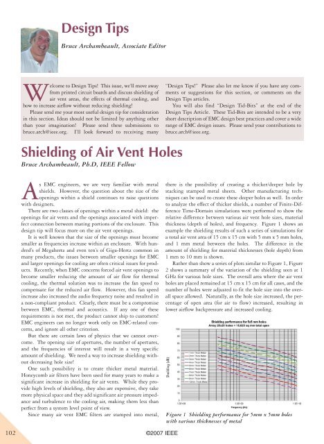
there is the possibility <strong>of</strong> creating a thicker/deeper hole by<br />
stacking stamped metal sheets. Other manufacturing techniques<br />
can be used to create these deeper holes as well. In order<br />
to analyze the effect <strong>of</strong> thicker shields, a number <strong>of</strong> Finite-Difference<br />
Time-Domain simulations were performed to show the<br />
relative difference between various air vent hole sizes, material<br />
thickness (depth <strong>of</strong> holes), and frequency. Figure 1 shows an<br />
example the shielding results <strong>of</strong> such a series <strong>of</strong> simulations for<br />
a total air vent area <strong>of</strong> 15 cm x 15 cm with 5 mm x 5 mm holes,<br />
and 1 mm metal between the holes. The difference in the<br />
amount <strong>of</strong> shielding for material thicknesses (hole depth) from<br />
1 mm to 10 mm is shown.<br />
Rather than show a series <strong>of</strong> plots similar to Figure 1, Figure<br />
2 shows a summary <strong>of</strong> the variation <strong>of</strong> the shielding seen at 1<br />
GHz for various hole sizes. The overall area where the air vent<br />
holes are placed remained at 15 cm x 15 cm for all cases, and the<br />
number <strong>of</strong> holes were adjusted to fit the hole size into the overall<br />
space allowed. Naturally, as the hole size increased, the percentage<br />
<strong>of</strong> open area (for air to flow) increased, resulting in<br />
lower airflow backpressure and increased cooling.<br />
Sheilding (dB)<br />
Figure 1 <strong>Shielding</strong> performance for 5mm x 5mm holes<br />
with various thicknesses <strong>of</strong> metal
One <strong>of</strong> the main reasons for plots such as Figure 2 is to make<br />
design decisions on engineering trade-<strong>of</strong>fs. For example, let’s<br />
suppose that previous product testing has shown that a product<br />
using 4 mm x 4 mm holes (with a single metal sheet thickness<br />
<strong>of</strong> 1 mm) needs 40 dB <strong>of</strong> shielding at 1 GHz. However, because<br />
<strong>of</strong> thermal constraints, the hole size should be increased to 7<br />
mm x 7 mm, Figure 2 shows that if the depth <strong>of</strong> the holes<br />
(thickness <strong>of</strong> the metal) is increased to 4 mm, then the required<br />
40 dB <strong>of</strong> shielding at 1 GHz is maintained.<br />
Summary<br />
The results in Figures 1 and 2 show the trade-<strong>of</strong>fs available to<br />
design engineers to increase airflow, improve cooling, and to maintain<br />
electromagnetic shielding performance. These results show<br />
the relative shielding performance for an air vent area <strong>of</strong> 15 cm x<br />
15 cm. Other overall areas will have different levels <strong>of</strong> shielding,<br />
but the trends shown in this <strong>Design</strong> Tip will be consistent.<br />
<strong>Design</strong> Tid-Bit<br />
©2007 <strong>IEEE</strong><br />
Figure 2 <strong>Shielding</strong> performance at 1 GHz for various hole<br />
sizes and thicknesses.<br />
Insufficient consideration <strong>of</strong> signal return current is one <strong>of</strong> the main causes <strong>of</strong> poor EMI<br />
performance in printed circuit boards (PCBs). The main causes <strong>of</strong> poor return current<br />
design is <strong>of</strong>ten the high-speed signal trace changing layers in the PCB and effectively<br />
changing the reference layer where the return current must flow. Maintaining a return via<br />
that connects the two return planes within five times the plane-to-plane distance will help<br />
minimize the return current spread and, therefore, the EMI noise between the planes. The<br />
closer the return via is to the signal via, the lower the EMI noise created by this signal via.<br />
Sheilding Performance(dB)<br />
--- Bruce Archambeault<br />
103


