

1959 - History of Ericsson - History of Ericsson
1959 - History of Ericsson - History of Ericsson
1959 - History of Ericsson - History of Ericsson

Create successful ePaper yourself
Turn your PDF publications into a flip-book with our unique Google optimized e-Paper software.
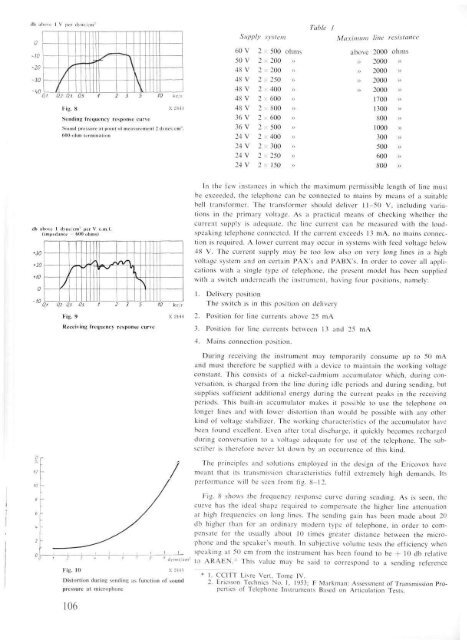
Fig. 8 X 2443<br />
Sending frequency response curve<br />
Sound pressure at point <strong>of</strong> measurement 2 dynes/cm".<br />
600-ohm termination<br />
Fig. 9<br />
Receiving frequency response curve<br />
dynes/cm-<br />
Fig. 10 X 2445<br />
Distortion during sending as function <strong>of</strong> sound<br />
pressure at microphone<br />
106<br />
In the few instances in which the maximum permissible length <strong>of</strong> line must<br />
be exceeded, the telephone can be connected to mains by means <strong>of</strong> a suitable<br />
hell transformer. The transformer should deliver 11-50 V, including variations<br />
in the primary voltage. As a practical means <strong>of</strong> checking whether the<br />
current supply is adequate, the line current can be measured with the loudspeaking<br />
telephone connected. If the current exceeds 13 mA, no mains connection<br />
is required. A lower current may occur in systems with feed voltage below<br />
48 V. The current supply may be too low also on very long lines in a high<br />
voltage system and on certain PAX's and PABX's. In order to cover all applications<br />
with a single type <strong>of</strong> telephone, the present model has been supplied<br />
with a switch underneath the instrument, having four positions, namely:<br />
1. Delivery position<br />
The switch is in this position on delivery<br />
2. Position for line currents above 25 mA<br />
3. Position for line currents between 13 and 25 mA<br />
4. Mains connection position.<br />
During receiving the instrument may temporarily consume up to 50 mA<br />
and must therefore be supplied with a device to maintain the working voltage<br />
constant. This consists <strong>of</strong> a nickel-cadmium accumulator which, during conversation,<br />
is charged from the line during idle periods and during sending, but<br />
supplies sufficient additional energy during the current peaks in the receiving<br />
periods. This built-in accumulator makes it possible to use the telephone on<br />
longer lines and with lower distortion than would be possible with any other<br />
kind <strong>of</strong> voltage stabilizer. The working characteristics <strong>of</strong> the accumulator have<br />
been found excellent. Even after total discharge, it quickly becomes recharged<br />
during conversation to a voltage adequate for use <strong>of</strong> the telephone. The subscriber<br />
is therefore never let down by an occurrence <strong>of</strong> this kind.<br />
The principles and solutions employed in the design <strong>of</strong> the Ericovox have<br />
meant that its transmission characteristics fulfil extremely high demands. Its<br />
performance will be seen from fig. 8-12.<br />
Fig. 8 shows the frequency response curve during sending. As is seen, the<br />
curve has the ideal shape required to compensate the higher line attenuation<br />
at high frequencies on long lines. The sending gain has been made about 20<br />
db higher than for an ordinary modern type <strong>of</strong> telephone, in order to compensate<br />
for the usually about 10 times greater distance between the microphone<br />
and the speaker's mouth. In subjective volume tests the efficiency when<br />
speaking at 50 cm from the instrument has been found to be + 10 db relative<br />
to ARAEN.* This value may be said to correspond to a sending reference<br />
* 1. CCITT Livre Vert, Tome IV.<br />
2. <strong>Ericsson</strong> Technics No. 1, 1953; F Markman: Assessment <strong>of</strong> Transmission Properties<br />
<strong>of</strong> Telephone Instruments Based on Articulation Tests.


