

1959 - History of Ericsson - History of Ericsson
1959 - History of Ericsson - History of Ericsson
1959 - History of Ericsson - History of Ericsson

Create successful ePaper yourself
Turn your PDF publications into a flip-book with our unique Google optimized e-Paper software.
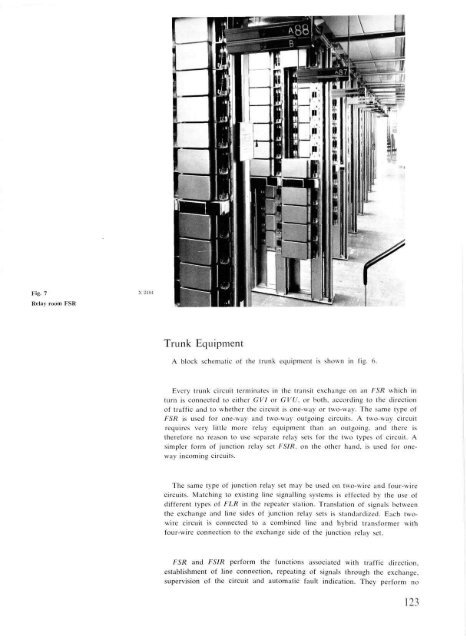
Fig. 7<br />
Relay room FSR<br />
x 2484<br />
Trunk Equipment<br />
A block schematic <strong>of</strong> the trunk equipment is shown in fig. 6.<br />
Every trunk circuit terminates in the transit exchange on an FSR which in<br />
turn is connected to either GVI or GVU, or both, according to the direction<br />
<strong>of</strong> traffic and to whether the circuit is one-way or two-way. The same type <strong>of</strong><br />
FSR is used for one-way and two-way outgoing circuits. A two-way circuit<br />
requires very little more relay equipment than an outgoing, and there is<br />
therefore no reason to use separate relay sets for the two types <strong>of</strong> circuit. A<br />
simpler form <strong>of</strong> junction relay set FSIR, on the other hand, is used for oneway<br />
incoming circuits.<br />
The same type <strong>of</strong> junction relay set may be used on two-wire and four-wire<br />
circuits. Matching to existing line signalling systems is effected by the use <strong>of</strong><br />
different types <strong>of</strong> FLR in the repeater station. Translation <strong>of</strong> signals between<br />
the exchange and line sides <strong>of</strong> junction relay sets is standardized. Each twowire<br />
circuit is connected to a combined line and hybrid transformer with<br />
four-wire connection to the exchange side <strong>of</strong> the junction relay set.<br />
FSR and FSIR perform the functions associated with traffic direction,<br />
establishment <strong>of</strong> line connection, repeating <strong>of</strong> signals through the exchange,<br />
supervision <strong>of</strong> the circuit and automatic fault indication. They perform no<br />
123


