

1959 - History of Ericsson - History of Ericsson
1959 - History of Ericsson - History of Ericsson
1959 - History of Ericsson - History of Ericsson

You also want an ePaper? Increase the reach of your titles
YUMPU automatically turns print PDFs into web optimized ePapers that Google loves.
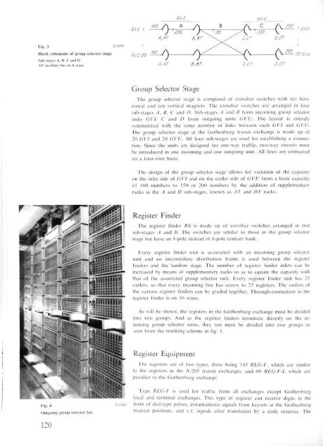
Fig. 3 x 8181<br />
Block schematic <strong>of</strong> group selector stage<br />
Sub-stages A, B, C and D<br />
AT auxiliary bay in A stage<br />
Fig. 4<br />
Outgoing group selector bay<br />
120<br />
x 2482<br />
Group Selector Stage<br />
The group selector stage is composed <strong>of</strong> crossbar switches with ten horizontal<br />
and ten vertical magnets. The crossbar switches are arranged in four<br />
sub-stages A, B, C and D. Sub-stages A and B form incoming group selector<br />
units GVI; C and D form outgoing units GVU. The layout is entirely<br />
symmetrical with the same number <strong>of</strong> links between each GVI and GVU.<br />
The group selector stage at the Gothenburg transit exchange is made up <strong>of</strong><br />
20 GVI and 20 GVU. All four sub-stages are used for establishing a connection.<br />
Since the units are designed for one-way traffic, two-way circuits must<br />
be introduced in one incoming and one outgoing unit. All lines are connected<br />
on a four-wire basis.<br />
The design <strong>of</strong> the group selector stage allows for variation <strong>of</strong> the capacity<br />
on the inlet side <strong>of</strong> GVI and on the outlet side <strong>of</strong> GVU from a basic capacity<br />
<strong>of</strong> 100 numbers to 150 or 200 numbers by the addition <strong>of</strong> supplementary<br />
racks in the A and D sub-stages, known as AT and DT racks.<br />
Register Finder<br />
The register finder RS is made up <strong>of</strong> crossbar switches arranged in two<br />
sub-stages A and B. The switches are similar to those in the group selector<br />
stage but have an 8-pole instead <strong>of</strong> 6-pole contact bank.<br />
Every register finder unit is associated with an incoming group selector<br />
unit and no intermediate distribution frame is used between the register<br />
finders and the tandem stage. The number <strong>of</strong> register finder inlets can be<br />
increased by means <strong>of</strong> supplementary racks so as to equate the capacity with<br />
that <strong>of</strong> the associated group selector unit. Every register finder unit has 25<br />
outlets, so that every incoming line has access to 25 registers. The outlets <strong>of</strong><br />
the various register finders can be graded together. Through-connection in the<br />
register finder is on 16 wires.<br />
As will be shown, the registers in the Gothenburg exchange must be divided<br />
into two groups. And as the register finders terminate directly on the incoming<br />
group selector units, they too must be divided into two groups as<br />
seen from the trunking scheme in fig. 1.<br />
Register Equipment<br />
The registers are <strong>of</strong> two types, there being 145 REG-F, which are similar<br />
to the registers in the A-205 transit exchanges, and 60 REG-F-L which are<br />
peculiar to the Gothenburg exchange.<br />
Type REG-F is used for traffic from all exchanges except Gothenburg<br />
local and terminal exchanges. This type <strong>of</strong> register can receive digits in the<br />
form <strong>of</strong> dial-type pulses, instantaneous signals from keysets at the Gothenburg<br />
manual positions, and v.f. signals after translation by a code receiver. The


