

1959 - History of Ericsson - History of Ericsson
1959 - History of Ericsson - History of Ericsson
1959 - History of Ericsson - History of Ericsson

You also want an ePaper? Increase the reach of your titles
YUMPU automatically turns print PDFs into web optimized ePapers that Google loves.
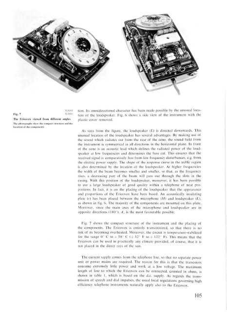
Fig. 7<br />
X 8162<br />
x 8161<br />
The Ericovox viewed from different angles<br />
The photographs show the compact structure and the<br />
location <strong>of</strong> the components<br />
tion. Its omnidirectional character has been made possible by the unusual location<br />
<strong>of</strong> the loudspeaker. Fig. 6 shows a side view <strong>of</strong> the instrument with the<br />
plastic cover removed.<br />
As seen from the figure, the loudspeaker (L) is directed downwards. This<br />
unusual location <strong>of</strong> the ioudspeaker has several advantages. By making use <strong>of</strong><br />
the sound which radiates out from the rear <strong>of</strong> the cone, the sound field from<br />
the instrument is symmetrical in all directions in the horizontal plane. In front<br />
<strong>of</strong> the cone is an acoustic load which defines the radiated power <strong>of</strong> the loudspeaker<br />
at low frequencies and determines the bass cut. This ensures that the<br />
received signal is comparatively free from low frequency disturbances, e.g. from<br />
the electric power supply. The shape <strong>of</strong> the response curve in the treble region<br />
is also determined by the location <strong>of</strong> the loudspeaker. At higher frequencies<br />
the width <strong>of</strong> the beam becomes smaller and smaller, so that, as the frequency<br />
rises, a decreasing part <strong>of</strong> the beam will pass out through the slots in the<br />
casing. With this position <strong>of</strong> the loudspeaker, moreover, it has been possible<br />
to use a large loudspeaker <strong>of</strong> good quality within a telephone <strong>of</strong> neat proportions.<br />
In fact, it is on the placing <strong>of</strong> the loudspeaker that the appearance<br />
and proportions <strong>of</strong> the Ericovox have been based. An acoustically insulating<br />
plate (c) has been placed between the microphone (M) and loudspeaker (L),<br />
as shown in fig. 6. The majority <strong>of</strong> the components are mounted on this plate.<br />
Moreover, since the main axes <strong>of</strong> the microphone and loudspeaker are in<br />
opposite directions (180°), Aa is the most favourable possible.<br />
Fig. 7 shows the compact structure <strong>of</strong> the instrument and the placing <strong>of</strong><br />
the components. The Ericovox is entirely transistorized, so that there is no<br />
risk <strong>of</strong> its becoming overheated. Moreover, the circuit is temperature-stabilized<br />
for the range 0° C to + 50° C (+ 32° F to + 122° F). This means that the<br />
Ericovox can be used in practically any climate provided, <strong>of</strong> course, that it is<br />
not placed in the direct rays <strong>of</strong> the sun.<br />
The current supply comes from the telephone line, so that no separate power<br />
unit or power mains are required. The reason for this is that the transistors<br />
consume extremely little power and work at a low voltage. The maximum<br />
length <strong>of</strong> line to which the Ericovox can be connected, counted in ohms, is<br />
shown in table 1, which is based on the d.c. supply. As regards the transmission<br />
<strong>of</strong> speech and dial impulses, the usual local regulations governing high<br />
efficiency telephone instruments naturally apply also to the Ericovox.<br />
105


