

1959 - History of Ericsson - History of Ericsson
1959 - History of Ericsson - History of Ericsson
1959 - History of Ericsson - History of Ericsson

You also want an ePaper? Increase the reach of your titles
YUMPU automatically turns print PDFs into web optimized ePapers that Google loves.
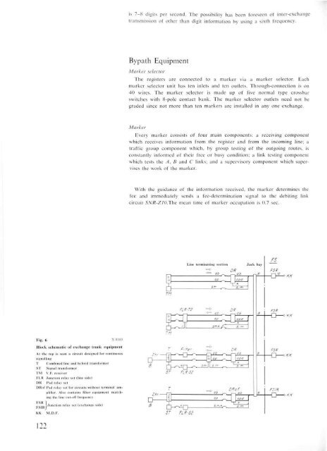
Fig. 6<br />
122<br />
x 8180<br />
Block schematic <strong>of</strong> exchange trunk equipment<br />
At the top is seen a circuit designed for continuous<br />
signalling<br />
T Combined line and hybrid transformer<br />
ST Signal transformer<br />
TM V.F. receiver<br />
FLR Junction relay set (line side)<br />
DR Pad relay set<br />
DR<strong>of</strong> Pad relay set for circuits without terminal amplifier.<br />
Also contains filter equipment matching<br />
the line cut-<strong>of</strong>f frequency<br />
„„ ^Junction relav set (exchange side)<br />
FSfRJ<br />
KK M.D.F.<br />
is 7-8 digits per second. The possibility has been foreseen <strong>of</strong> inter-exchange<br />
transmission <strong>of</strong> other than digit information by using a sixth frequency.<br />
Bypath Equipment<br />
Marker selector<br />
The registers are connected to a marker via a marker selector. Each<br />
marker selector unit has ten inlets and ten outlets. Through-connection is on<br />
40 wires. The marker selector is made up <strong>of</strong> five normal type crossbar<br />
switches with 8-pole contact bank. The marker selector outlets need not be<br />
graded since not more than ten markers are installed in any one exchange.<br />
Marker<br />
Every marker consists <strong>of</strong> four main components: a receiving component<br />
which receives information from the register and from the incoming line; a<br />
traffic group component which, by group testing <strong>of</strong> the outgoing routes, is<br />
constantly informed <strong>of</strong> their free or busy condition; a link testing component<br />
which tests the A, B and C links; and a supervisory component which supervises<br />
the work <strong>of</strong> the marker.<br />
With the guidance <strong>of</strong> the information received, the marker determines the<br />
fee and immediately sends a fee-determination signal to the debiting link<br />
circuit SNR-ZIO.The mean time <strong>of</strong> marker occupation is 0.7 sec.


