

1959 - History of Ericsson - History of Ericsson
1959 - History of Ericsson - History of Ericsson
1959 - History of Ericsson - History of Ericsson

Create successful ePaper yourself
Turn your PDF publications into a flip-book with our unique Google optimized e-Paper software.
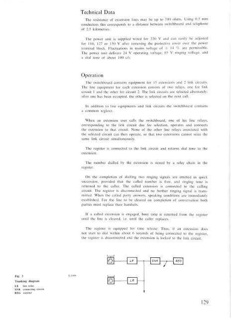
Fig. 3 X2464<br />
Trunking diagram<br />
LR line relay<br />
SNR connecting circuit<br />
REG register<br />
Technical Data<br />
The resistance <strong>of</strong> extension lines may be up to 500 ohms. Using 0.5 mm<br />
conductors this corresponds to a distance between switchboard and telephone<br />
<strong>of</strong> 2.5 kilometres.<br />
The power unit is supplied wired for 220 V and can easily be adjusted<br />
for 110, 127 or 150 V after removing the protective cover over the power<br />
terminal block. Fluctuations in mains voltage <strong>of</strong> ± 14 % are permissible.<br />
The power unit delivers 24 V operating voltage, 85 V ringing voltage, and<br />
a dial tone <strong>of</strong> about 100 c/s.<br />
Operation<br />
The switchboard contains equipment for 15 extensions and 2 link circuits.<br />
The line equipment for each extension consists <strong>of</strong> two relays, one for link<br />
circuit 1 and the other for circuit 2. The link circuits are selected alternately:<br />
after one has been occupied, the other is selected on the next call.<br />
In addition to line equipments and link circuits the switchboard contains<br />
a common register.<br />
When an extension user calls the switchboard, one <strong>of</strong> his line relays,<br />
corresponding to the link circuit due for selection, operates and connects<br />
the extension to that circuit. None <strong>of</strong> the other line relays associated with<br />
the selected circuit can then operate, so that two extensions cannot seize the<br />
same link circuit simultaneously.<br />
The register is connected to the link circuit and returns dial tone to the<br />
extension.<br />
The number dialled by the extension is stored by a relay chain in the<br />
register.<br />
On the completion <strong>of</strong> dialling two ringing signals are emitted in quick<br />
succession, provided that the called number is free, and ringing tone is<br />
returned to the caller. The called extension is connected to the calling<br />
circuit. The register is disconnected and no further ringing signal is transmitted.<br />
When the called party answers, speaking conditions are immediately<br />
established. For the line to be cleared on completion <strong>of</strong> conversation both<br />
parties must replace their handsets.<br />
If a called extension is engaged, busy tone is returned from the register<br />
until the line is cleared, i.e. until the caller replaces.<br />
The register is equipped for time release. Thus, if an extension does<br />
not start to dial within about 6 seconds <strong>of</strong> being connected to the register,<br />
the register is disconnected and the extension is locked to the link circuit.<br />
129


