Arbitrary Waveform Generator - Produktinfo.conrad.com
Arbitrary Waveform Generator - Produktinfo.conrad.com
Arbitrary Waveform Generator - Produktinfo.conrad.com

Create successful ePaper yourself
Turn your PDF publications into a flip-book with our unique Google optimized e-Paper software.
WGxx <strong>Arbitrary</strong> <strong>Waveform</strong> <strong>Generator</strong> Front Panel Operation<br />
Amplitude<br />
Offset<br />
The actual frequency value can be saved to a memory cell using a long push<br />
to buttons 1 to 3 . The corresponding button has to be pushed until a<br />
long beep appears. (The storage of frequency values is also possible if the<br />
LCD line 2 displays the mode line!)<br />
The stored value will be displayed in a shortened way. If, e.g., the value<br />
1.234kHz has been stored, the display indicates 1k23. Nevertheless, the<br />
storage cell contains the exact value of 1.234kHz.<br />
A signal beep will appear if the upper or lower frequency limit of the instrument<br />
is reached; in this case the frequency is set to the corresponding limit value.<br />
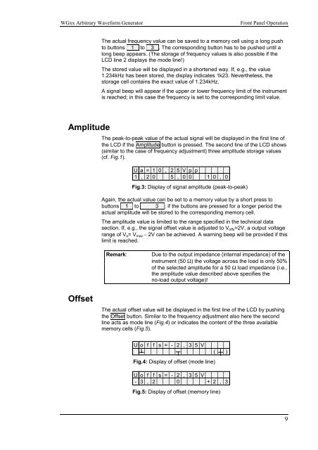
The peak-to-peak value of the actual signal will be displayed in the first line of<br />
the LCD if the Amplitude button is pressed. The second line of the LCD shows<br />
(similar to the case of frequency adjustment) three amplitude storage values<br />
(cf. Fig.1).<br />
U a = 1 0 , 2 5 V p p<br />
1 , 2 0 5 , 0 0 1 0 , 0<br />
Fig.3: Display of signal amplitude (peak-to-peak)<br />
Again, the actual value can be set to a memory value by a short press to<br />
buttons 1 to 3 ; if the buttons are pressed for a longer period the<br />
actual amplitude will be stored to the corresponding memory cell.<br />
The amplitude value is limited to the range specified in the technical data<br />
section. If, e.g., the signal offset value is adjusted to Voffs=2V, a output voltage<br />
range of Va= Vmax − 2V can be achieved. A warning beep will be provided if this<br />
limit is reached.<br />
Remark: Due to the output impedance (internal impedance) of the<br />
instrument (50 Ω) the voltage across the load is only 50%<br />
of the selected amplitude for a 50 Ω load impedance (i.e.,<br />
the amplitude value described above specifies the<br />
no-load output voltage)!<br />
The actual offset value will be displayed in the first line of the LCD by pushing<br />
the Offset button. Similar to the frequency adjustment also here the second<br />
line acts as mode line (Fig.4) or indicates the content of the three available<br />
memory cells (Fig.5).<br />
U o f f s = - 2 , 3 5 V<br />
Fig.4: Display of offset (mode line)<br />
( )<br />
U o f f s = - 2 , 3 5 V<br />
- 3 , 2 0 + 2 , 3<br />
Fig.5: Display of offset (memory line)<br />
9