Welding Fabrication Standards - EWF
Welding Fabrication Standards - EWF
Welding Fabrication Standards - EWF

Create successful ePaper yourself
Turn your PDF publications into a flip-book with our unique Google optimized e-Paper software.
<strong>Welding</strong> <strong>Fabrication</strong> <strong>Standards</strong> Page 49<br />
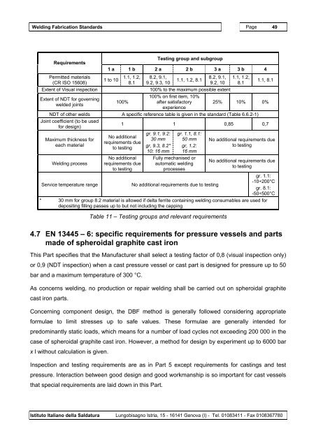
Requirements<br />
Permitted materials<br />
(CR ISO 15608)<br />
Testing group and subgroup<br />
1 a 1 b 2 a 2 b 3 a 3 b 4<br />
1 to 10<br />
1.1, 1.2,<br />
8.1<br />
8.2, 9.1,<br />
9.2, 9.3, 10<br />
1.1, 1.2, 8.1<br />
8.2, 9.1,<br />
9.2, 10<br />
Extent of Visual inspection 100% to the maximum possible extent<br />
Extent of NDT for governing<br />
welded joints<br />
100%<br />
100% on first item, 10%<br />
after satisfactory<br />
experience<br />
1.1, 1.2,<br />
8.1<br />
1.1, 8.1<br />
25% 10% 0%<br />
NDT of other welds A specific reference table is given in the standard (Table 6.6.2-1)<br />
Joint coefficient (to be used<br />
for design)<br />
1 1 0,85 0,7<br />
Maximum thickness for<br />
each material<br />
<strong>Welding</strong> process<br />
No additional<br />
requirements due<br />
to testing<br />
No additional<br />
requirements due<br />
to testing<br />
gr. 9.1, 9.2:<br />
30 mm<br />
gr, 9.3, 8.2*<br />
10: 16 mm<br />
gr. 1.1, 8.1:<br />
50 mm<br />
gr, 1.2:<br />
16 mm<br />
Fully mechanised or<br />
automatic welding<br />
processes<br />
No additional requirements due<br />
to testing<br />
No additional requirements due<br />
to testing<br />
Service temperature range No additional requirements due to testing<br />
gr. 1.1:<br />
-10÷200°C<br />
gr. 8.1:<br />
-50÷500°C<br />
* 30 mm for group 8.2 material is allowed if delta ferrite containing welding consumables are used for<br />
depositing filling passes up to but not including the capping<br />
Table 11 – Testing groups and relevant requirements<br />
4.7 EN 13445 – 6: specific requirements for pressure vessels and parts<br />
made of spheroidal graphite cast iron<br />
This Part specifies that the Manufacturer shall select a testing factor of 0,8 (visual inspection only)<br />
or 0,9 (NDT inspection) when a cast pressure vessel or cast part is designed for pressure up to 50<br />
bar and a maximum temperature of 300 °C.<br />
As concerns welding, no production or repair welding shall be carried out on spheroidal graphite<br />
cast iron parts.<br />
Concerning component design, the DBF method is generally followed considering appropriate<br />
formulae to limit stresses up to safe values. These formulae are generally intended for<br />
predominantly static loads, which means for a number of load cycles not exceeding 200 000 in the<br />
case of spheroidal graphite cast iron. However, a method for design by experiment up to 6000 bar<br />
x l without calculation is given.<br />
Inspection and testing requirements are as in Part 5 except requirements for castings and test<br />
pressure. Interaction between good design and good workmanship is so important for cast vessels<br />
that special requirements are laid down in this Part.<br />
Istituto Italiano della Saldatura Lungobisagno Istria, 15 - 16141 Genova (I) - Tel. 01083411 - Fax 0108367780