PHILOS + PHILOS Long. - ShoulderDoc.co.uk
PHILOS + PHILOS Long. - ShoulderDoc.co.uk
PHILOS + PHILOS Long. - ShoulderDoc.co.uk

Create successful ePaper yourself
Turn your PDF publications into a flip-book with our unique Google optimized e-Paper software.
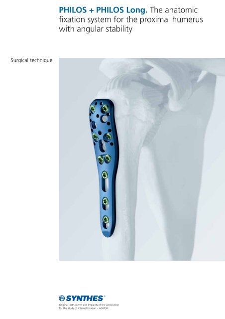
Surgical technique<br />
<strong>PHILOS</strong> + <strong>PHILOS</strong> <strong>Long</strong>. The anatomic<br />
fixation system for the proximal humerus<br />
with angular stability
Table of Contents<br />
Indications/<strong>co</strong>ntraindications 2<br />
Implants/instruments 3<br />
Surgical technique 5<br />
Surgical technique for Philos <strong>Long</strong> 14<br />
Postoperative treatment 15<br />
Implant removal 16<br />
Image intensifier <strong>co</strong>ntrol<br />
Warning<br />
This description is not sufficient for immediate application of<br />
the instrumentation. Instruction by a surgeon experienced in<br />
handling this instrumentation is highly re<strong>co</strong>mmended.<br />
Synthes <strong>PHILOS</strong> + <strong>PHILOS</strong> <strong>Long</strong> Surgical technique<br />
1
Indications/<strong>co</strong>ntraindications<br />
Indications for Philos<br />
– Dislocated two-, three-, and four-fragment fractures of the<br />
proximal humerus, including fractures involving osteopenic<br />
bone<br />
– Pseudarthroses in the proximal humerus<br />
– Osteotomies in the proximal humerus<br />
Contraindications<br />
– Acute infections<br />
– Children during the growth phase<br />
Indications for Philos long<br />
– As for Philos, but for fractures extending into the shaft or<br />
without medial support<br />
Contraindications<br />
– Acute infections<br />
– Children during the growth phase<br />
– Isolated shaft fractures<br />
2 Synthes <strong>PHILOS</strong> + <strong>PHILOS</strong> <strong>Long</strong> Surgical technique
Implants/Instruments<br />
Philos Proximal Humeral Internal Locking System<br />
– Plate length 90 mm, short, 3 shaft holes (X41.901)<br />
– Plate length 114 mm, long, 5 shaft holes (X41.903)<br />
– 9 proximal screw holes in section A–E<br />
for LCP locking screws 3.5 mm<br />
– 10 proximal suture holes<br />
– 3 or 5 distal LCP Combi-holes in the shaft section F–H (or F–J)<br />
for <strong>co</strong>rtex screws 3.5 mm and cancellous bone screws<br />
4.0 mm, as well as LCP locking screws 3.5 mm<br />
– Available in pure titanium (CPTI) and implant steel (SSt)<br />
Philos long<br />
– Proximal part identical to Philos<br />
– Shaft reinforced<br />
– Plate length 140 to 270 mm<br />
– 5, 6, 8, 10, and 12 elongated holes in the shaft<br />
LCP locking screws 3.5 mm (413.020–413.060)<br />
– Self-tapping locking screw lengths:<br />
20 mm 30 mm 40 mm 50 mm 60 mm<br />
22 mm 32 mm 42 mm 52 mm<br />
24 mm 35 mm 45 mm 55 mm<br />
26 mm 38 mm 48 mm<br />
28 mm<br />
The LCP locking screws 3.5 mm are also available with Stardrive<br />
(412.101–412.124)<br />
Philos Aiming Device (323.050 hexagonal,<br />
323.051 Stardrive)<br />
A<br />
B<br />
C<br />
D<br />
E<br />
F<br />
G<br />
H<br />
3
Drill Sleeve System for Philos Aiming Device<br />
323.053 Centering Sleeve for Philos Aiming Device<br />
323.054 Drill Sleeve for Philos Aiming Device<br />
323.055 Centering Sleeve for Kirschner Wire 1.6 mm<br />
Philos direct measuring device (323.060)<br />
4 Synthes <strong>PHILOS</strong> + <strong>PHILOS</strong> <strong>Long</strong> Surgical technique
Surgical technique for Philos<br />
Experience in the use of LCP or instruction by a surgeon with<br />
<strong>co</strong>rresponding experience is re<strong>co</strong>mmended (see also the Synthes<br />
Surgical Technique for LCP 036.000.019).<br />
1<br />
Position of the patient and approach<br />
Surgery is normally performed with the patient in the beachchair<br />
position or supine position. A deltopectoral or transdeltoid<br />
approach is re<strong>co</strong>mmended.<br />
2<br />
Reduce fracture and fix provisionally<br />
Reduce the head fragments and check the reduction under the<br />
image intensifier. Fix the reduction with Kirschner wires.<br />
Note: The locking screws are not suitable for reduction since<br />
they cannot exert <strong>co</strong>mpression. The head fragments must be reduced<br />
before insertion of the locking screws.<br />
Option<br />
The stability of the structure will be improved with the insertion<br />
of sutures. The insertion of sutures is especially re<strong>co</strong>mmended<br />
in weak bone where only short screws can be used because of<br />
the risk of penetration through settling.<br />
Draw the sutures through the appropriate holes before placing<br />
the plate against the bone. Provisionally reduce the tubercles<br />
using sutures and position the plate exactly (see step 3 on<br />
page 6) by placing one or more thick sutures in the region of the<br />
insertion of the supraspinatus, infraspinatus, and the subcapsular<br />
tendon.<br />
5
3<br />
Attach aiming device to plate<br />
Insert the stabilization pin of the aiming device in the specially<br />
provided hole on the Philos plate. Use the screwdriver to tighten<br />
the securing screw of the aiming device.<br />
Required instruments<br />
Philos aiming device (hexagonal) 323.050<br />
or<br />
Philos aiming device (Stardrive) 323.051<br />
Screwdriver shaft hexagonal 314.030<br />
or<br />
Screwdriver shaft Stardrive T15 314.116<br />
6 Synthes <strong>PHILOS</strong> + <strong>PHILOS</strong> <strong>Long</strong> Surgical technique
4<br />
Position plate<br />
Position the plate proximally at least 8 mm distal to the upper<br />
end of the greater tubercle (rotator cuff insertion). Determine<br />
the position of the plate using a Kirschner wire. Insert the<br />
Kirschner wire into the proximal guide hole of the insertion<br />
guide below the rotator cuff so that the Kirschner wire aims at<br />
the proximal joint surface.<br />
Note: Placing the plate at too high a level increases the risk of<br />
subacromial impingement. Placing the plate too low can prevent<br />
the optimal distribution of screws in the humerus head and<br />
make it impossible to insert screws in section “E”. Centre the<br />
plate laterally against the greater tubercle, ensuring that a sufficient<br />
gap is maintained between the plate and the long biceps<br />
tendon (arterial blood supply).<br />
7
5<br />
Define the position of the screws<br />
Before inserting the screws, check the subsequent position of<br />
the screws using Kirschner wires. Insert one Kirschner wire<br />
in each case in sections A and E as follows: Attach a drill sleeve<br />
system, <strong>co</strong>nsisting of a centering sleeve for the Philos aiming<br />
device, a drill sleeve for the Philos aiming device, and a centering<br />
sleeve for the Kirschner wire (323.055), onto the aiming<br />
device and insert a Kirschner wire 1.6 mm, 150 mm long. Check<br />
the position of both Kirschner wires under the image intensifier.<br />
Note: If possible, the distal Kirschner wire should be positioned<br />
approx. 5 mm above the “calcar”. Insert the locking screws in<br />
the proximal section (A to E) depending on the respective fracture<br />
situation, as described in the following steps 6 and 7.<br />
Ideally, the plate should be secured with at least 4 or 6 proximal<br />
screws or more, particularly if the bone quality is poor.<br />
Required instruments<br />
Centering sleeve for the Philos Aiming Device 323.053<br />
Drill sleeve for the Philos Aiming Device 323.054<br />
Centering sleeve for the Kirschner wire 323.055<br />
Kirschner Wire 1.6 mm, 150 mm long 292.160<br />
8 Synthes <strong>PHILOS</strong> + <strong>PHILOS</strong> <strong>Long</strong> Surgical technique
6<br />
Determine the length of the proximal screws and predrill<br />
screw hole<br />
a. Using the Kirschner wire<br />
Check the position of the Kirschner wire. The tip of the Kirschner<br />
wire should be located in the subchondral bone (5–8 mm below<br />
the joint surface). Slide the Philos direct measuring device for<br />
Kirschner wire 1.6 mm over the Kirschner wire and determine the<br />
length of the required screw.<br />
Required instruments<br />
Philos Direct Measuring Device 323.060<br />
Depth Gauge 319.010<br />
Drill Bit 2.8 mm 310.284<br />
Remove the direct measuring device, the Kirschner wire, and the<br />
centering sleeve for Kirschner wire. Using a drill bit 2.8 mm,<br />
predrill the screw hole. Remove the drill bit and the drill sleeve.<br />
Alternative<br />
b. Using the depth gauge<br />
Remove the Kirschner wire and the centering sleeve for Kirschner<br />
wire. Using a drill bit 2.8 mm (310.284), predrill the screw hole<br />
through both <strong>co</strong>rtices. Remove the drill bit and the drill sleeve.<br />
Determine the screw length through both <strong>co</strong>rtices using<br />
the depth gauge. Deduct 10 mm from the measured reading.<br />
50<br />
60<br />
50 60<br />
9
7<br />
Insert proximal screws<br />
The proximal locking screws (plate holes A–E) can be inserted either<br />
using a power tool or manually.<br />
To insert the locking screw using a power tool, fit a torque limiter<br />
to the power tool.<br />
Required instruments<br />
Torque limiter, 1.5 Nm 511.770<br />
or 511.773<br />
Screwdriver Shaft hexagonal 314.030<br />
or<br />
Screwdriver Shaft Stardrive T15 314.116<br />
Centering Sleeve for Philos Aiming Device 323.054<br />
Handle for Torque Limiter 311.431<br />
or 397.705<br />
Insert the screwdriver shaft. Pick up the locking screw and insert<br />
it through the centering sleeve for the Philos aiming device into<br />
the plate hole. To insert the screw, start the power tool slowly,<br />
increase the speed and then reduce it again before the screw is<br />
fully tightened. The torque is automatically limited and a clearly<br />
audible click signifies that the torque limit has been reached.<br />
Stop the power tool and dis<strong>co</strong>nnect from the screw.<br />
Note: Do not lock the screws at full speed as this risks damaging<br />
the screw recess, which would make implant removal more<br />
difficult.<br />
10 Synthes <strong>PHILOS</strong> + <strong>PHILOS</strong> <strong>Long</strong> Surgical technique<br />
Philos 06a
Alternative<br />
To insert the locking screw manually, attach a torque limiter to<br />
the handle and insert a screwdriver shaft. Insert the locking<br />
screw through the centering sleeve. The torque is automatically<br />
limited and a clearly audible click signifies that the torque limit<br />
has been reached.<br />
Repeat steps 6 and 7 until all desired proximal locking screws A<br />
to E are inserted. Remove the aiming device.<br />
11
8<br />
Distal fixation<br />
Fix the Philos plate distally. Plate holes F to H, or F to J, are LCP<br />
Combi-holes.<br />
An LCP Combi-hole can be fixed with a standard screw (<strong>co</strong>rtex<br />
or cancellous bone screw) to generate interfragmentary<br />
<strong>co</strong>mpression. In this case, the screws are inserted ac<strong>co</strong>rding to<br />
the technique for fixing LC-DCP standard plates, but using<br />
the universal drill guide instead of the LC-DCP drill guide.<br />
The insertion of an angularly-stable LCP locking screw in the<br />
Combi-hole is described in the following steps 9 to 12.<br />
Note: For more stable fixation and to reduce the risk of screw<br />
loosening in the diaphysis, the use of bi<strong>co</strong>rtical self-tapping<br />
screws in the distal section of the plate is re<strong>co</strong>mmended.<br />
Required instruments<br />
LC-DCP Drill Sleeve 323.360<br />
9<br />
Insert LCP guide sleeve in distal plate hole<br />
Carefully screw the LCP drill sleeve into the threaded section of<br />
the desired Combi-hole until it is gripped <strong>co</strong>mpletely by the<br />
thread. The LCP guide sleeve ensures that the locking screw is<br />
<strong>co</strong>rrectly locked in the plate. The angular stability is reduced if a<br />
locking screw is inserted obliquely.<br />
Note: The threaded hole is perpendicular to the plane of the<br />
plate.<br />
Required instruments<br />
LCP Drill Sleeve 323.027<br />
12 Synthes <strong>PHILOS</strong> + <strong>PHILOS</strong> <strong>Long</strong> Surgical technique
10<br />
Predrill screw hole<br />
Predrill the screw hole with a drill bit 2.8 mm passing through<br />
both <strong>co</strong>rtices.<br />
Remove the LCP guide sleeve.<br />
Required instruments<br />
Drill bit 2.8 mm 310.284<br />
11<br />
Determine screw length<br />
Using the depth gauge, determine the screw length.<br />
Required instruments<br />
Depth gauge 310.010<br />
12<br />
Insert distal screws<br />
Insert the locking screws manually or using a power tool as described<br />
step 7 on page 10. The distal locking screws must be<br />
locked in the Combi-hole at an angle of 90° to ensure optimal<br />
stability.<br />
Insert all distal screws (depending on the particular plate, 3–5<br />
locking screws or standard screws).<br />
30 40 50 60<br />
13
Surgical technique for Philos <strong>Long</strong><br />
The surgical technique is essentially identical to that for the<br />
Philos plate. However, the following points should be <strong>co</strong>nsidered<br />
in particular.<br />
Approach<br />
The approach must normally be lengthened because of the<br />
plate. An extended deltopectoral approach is possible.<br />
Position plate<br />
The positioning of the Philos <strong>Long</strong> requires a partially lateral section<br />
of the deltoid muscle. Alternatively, the plate can also be<br />
advanced into the middle of the muscle insertion.<br />
Note: The plate can be shaped with the bending tools. It can<br />
then also be guided in the form of a spiral toward the anterior.<br />
Distal fixation<br />
The fracture and possible fragments are to be fixed with use of<br />
the elongated holes. This allows <strong>co</strong>nsiderable angulation when<br />
<strong>co</strong>rtical screws are used.<br />
Note: To achieve maximum stability, the shaft should be secured<br />
with at least 3 LCP screws.<br />
14 Synthes <strong>PHILOS</strong> + <strong>PHILOS</strong> <strong>Long</strong> Surgical technique
Postoperative treatment<br />
Start exercises as soon as possible after surgery to prevent later<br />
restrictions of movement. However, make absolutely sure<br />
that full load is exerted only after <strong>co</strong>mplete <strong>co</strong>nsolidation of the<br />
fracture.<br />
15
Implant removal<br />
To remove the plate, first unlock all screws with the screwdriver<br />
before removing them definitively in a se<strong>co</strong>nd step, otherwise<br />
the plate may rotate while the last screw is being removed and<br />
cause soft tissue damage.<br />
If the screws cannot be removed with the screwdriver (e.g., if<br />
the hexagonal recess of the locking screw is damaged or if<br />
the screws are stuck in the plate), loosen the <strong>co</strong>nical extraction<br />
screw with a left-handed thread using the T-handle with quick<br />
<strong>co</strong>upling by turning <strong>co</strong>unterclockwise.<br />
Required instruments<br />
Screwdriver Shaft hexagonal 314.030<br />
or<br />
Screwdriver Shaft Stardrive T15 314.116<br />
Extraction Screw with Left-handed Thread 309.521<br />
16 Synthes <strong>PHILOS</strong> + <strong>PHILOS</strong> <strong>Long</strong> Surgical technique
Presented by:<br />
0123 036.000.166 SE_001076 AA © Stratec Medical 2005 Printed in Switzerland GRA Subject to modifications.