Tornier Fracture Surgical Technique
Tornier Fracture Surgical Technique
Tornier Fracture Surgical Technique

You also want an ePaper? Increase the reach of your titles
YUMPU automatically turns print PDFs into web optimized ePapers that Google loves.
VII.Metodología y estrategias de enseñanza aprendizajeEsta asignatura básica corresponde a la línea de formación geográfica y busca que losalumnos adquieran un conocimiento acabado sobre el origen, evolución y los debatescontemporáneos que se dan en la disciplina. La asignatura permitirá avanzar en laconstrucción de sólidos y actualizados conocimientos de los saberes propios de lageografía y las ciencias sociales El profesor realizará clases expositivas en donde seofrecerá una lectura general de los principales paradigmas del pensamiento geográfico,desde la formalización de la geografía en la época Greco-Romana hasta las nuevasconceptualizaciones nacidas bajo el amparo de la llamada sociedad postmoderna. Losalumnos tendrán un rol activo en el proceso de enseñanza-aprendizaje. Para cumplir conlo anterior, los alumnos deberán realizar ensayos críticos en cada una de las unidadescontempladas. Estos ensayos serán presentados oralmente ante el profesor y sus pares.En la misma línea, los alumnos participarán en 3 mesas redondas en donde se proveerá elescenario para el intercambio libre y crítico. El profesor actuará como moderadorinterviniendo para incentivar y profundizar la discusión.VIII.Evaluación:Pruebas parciales por unidad (60%)Ensayos críticos por unidad (30%)Participación en mesas redondas (10%)Los resultados de las evaluaciones mayores se deben dar a conocer una semana antes dela próxima evaluación.Con nota de reprobación 3.6 o superior los estudiantes tienen derecho a examen en lasfechas establecidas en el calendario académico.IX.Bibliografía:BásicaBOSQUE, J., ORTEGA, F. (1995) Comentario de textos geográficos: historia y crítica delpensamiento geográfico. Oikus-Tau: Barcelona.GARCÍA, A. (1992). Geografía y humanismo. Oikus-Tau: Barcelona.GÓMEZ, J., JIMÉNEZ, J., ORTEGA, N. (1988) El pensamiento geográfico: estudiointerpretativo y antología de textos: de Humboldt a las tendencias radicales. Editorialalianza: Madrid.
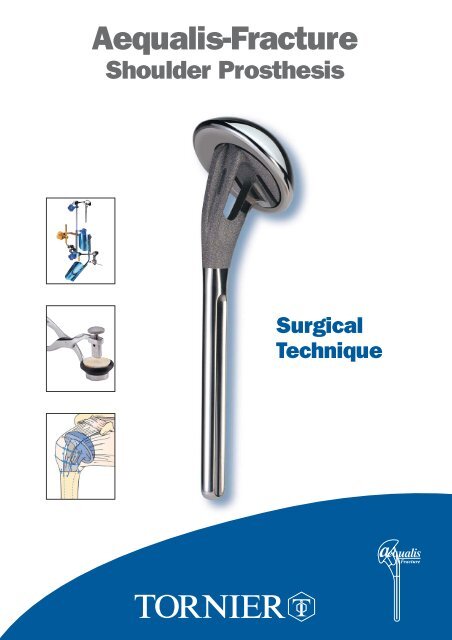
1. The prosthesisTHE AEQUALIS-FRACTURE SOLUTIONEccentric head(different sizes)Low profileOpen neck for bone graftingPolished medial neckto avoid abrasionsutureRough surfacefor maximal boneadhesionTitaniumPolished stemfor cementing130 mm length130° inclination6,5/9/12 mm diameter4
THE AEQUALIS-FRACTURE SOLUTIONThe Aequalis-<strong>Fracture</strong> JigThe Aequalis <strong>Fracture</strong> Jig is designed,to stabilize the prosthesis and,to assist the surgeon in more preciselypositioning the humeral implantin both height and retroversion.The bone graft cutterThe bone graft cutter is designed to removecancellous bone from the humeral headfor incorporation into the prostheticmetaphysis, improving the metaphysealbone adhesion.The standardized fixation techniquewith medial cerclage sutureDetachment and migration of the tuberositiesare the most common complications aftershoulder replacement for fractures.The quality of the suture wire and the techniquefor placing the tuberosities are critical.5
3. Deltopectoral approach and exposure:An incision is made from the tip of the coracoid process along the deltopectoral groove, slightlylaterally to avoid post-operative scars in the axillary fold. The deltopectoral groove is openedto the insertion of the pectoralis major, and the deltoid and cephalic vein are retracted laterally.The coracoid process is identified to allow the insertion of a Hohman retractor above it.The clavicular, acromial and humeral insertions of the deltoid are always preserved.The clavipectoral fascia is incised at the lateral border of the conjoined tendon of the coracobrachialisand the short head of the biceps. Usually the coracoacromial ligament is preserved.4. Identification of the lesser and greater tuberosities and anterosuperior arthrotomy:The glenohumeral joint is approached by extending the fracture line between the tuberosities,incising the rotator interval over the long head of the biceps tendon.8
5. Tenotomy and excision of the long head of biceps:6. Extraction of humeral head fragment and choice of prosthetic head:The diameter of the humeral headis measured either with a caliper,or by placing it on the corresponding sizepositioning hole of the trial head supporttray. In case of doubt between two sizes,always prefer the smaller diameter.The most common mistake is to usea too large humeral head.9
7. Placing of four horizontal stay sutures in the rotator cuff:Two non-absorbable sutures are placed in the infraspinatus tendon and two other are placed in the Teresminor tendon.8. Humeral reaming:With the arm in adduction, external rotation and extension, the humerus is progressively reamedusing cylindrical reamers of increasing diameter (6.5, 9 and 12 mm).The final reamer used will determine the diameter of the humeral stem.Cylindrical reamers of increasing sizesare advanced as far as the last ridge.10
9. Choice of trial prosthesis and attachment to the fracture jig:To accurately reestablish humeral head width, we recommend the use of a prosthetic humeral headof the same size as the removed head.The humeral head should be positioned either on the 1 or 8 index (depending whether it is a rightor left shoulder). This allows the highest lateral offset. Thereby the bone graft and the greatertuberosity are stabilized on the metaphyseal neck of the prosthesis.Position 1 or 8The trial prosthesis is secured to the prosthesis holder using to the two holes placed on the lowprofile lateral part of the implant. The prosthesis holder is then fixed to the fracture jig.Illustra11
10. Pre-fixing of height and retroversion:• The height has been defined by the pre-operative planning.• The retroversion is set at 20° which is an average value basedon anatomic studies from Gilles Walch and Pascal Boileau.The Aequalis-fracture jig is composed of:• a ruler, to determine the humeral height• a protractor, to determine the humeral retroversion.The humeral height is determined in relationto the metaphyso-diaphyseal axis (A-B), the top of the greatertuberosity (C) and the medial epicondyle (D),while the humeral retrotorsion is determined in relationto the axis of the epicondyles (D-E).XCAX'24252627N.B.: the proximal metaphyso-diaphyseal axis (A-B)represents the axis of the future prosthetic stem.It must not be confused with the diaphyseal axis, at the riskof causing a valgus position of the prosthesis and givinga false measurement of length.YBY'28293031323334BRAS GAUCHERETROTORSIONEDRETROTORSIONBRAS DROIT505040403 02010 012
11. Implantation and reduction of the trial prosthesis:Positioning of the remaining components of the fracture jig assembly (protractor, ruler,prosthesis holder and trial prosthesis) must be done with the arm in extension.Arm inextension.Once the trial prosthesis has been inserted into the humerus, the arm is placed in flexionto reduce the glenohumeral joint.Position of the arm.Trial prosthesis reduced.13
12. Identification of the epicondyles and stabilization of the trial prosthesis:The adjustment of height and retroversion begins by the placement of the epicondylar padson the medial and lateral epicondyles.The surgeon positions each epicondylar pad on the prominences of the lateral and medialepicondyles. At the same time, the assistant connects the protractor to the arm support, securingthe two angle joints by using knob n° 4.The fracture jig is then secured, allowing the selection of height and retroversion and a trial reduction.Knob n° 414
13. Reduction of the greater tuberosity around the trial prosthesis and testing of the heigh:The initial reduction of the prosthesis and the greater tuberosity enables both the height andthe retroversion to be tested. The greater tuberosity is placed on the diaphysis and the prosthesis,effectively testing the height of the prosthesis. There are three landmarks of interest:123The height of the acromiohumeral space, which is usually 10 mm.The top of the greater tuberosity, which should be located 5 mm below the upper limitof the prosthetic head.There must be no diastasis or overlap between the greater tuberosity and the humeraldiaphysis. The lesser tuberosity is then reduced to verify the adjustement with the greatertuberosity and the diaphysis. Once the all adjustements performed, the trial prosthesis is withdrow.14. Removal of the trial prosthesis:The shoulder is placed in extension to dislocate the trial prosthesis.The prosthetic holder and the trial are prosthesis are removed, leaving the remaining of the fracturejig in place.15. Drilling the diaphysis and placement, of the 2 vertical sutures:Two holes are drilled on each side of the bicipital groove.Two non-absorbable sutures are passed through the holes.15
16. Assembling the implant:➔ AssemblingThe assemby of the implant is done by impactionof the prosthetic head onto the stem.The assembly is secured by a morse taper system.The prosthetic head is positioned on the stem, aligningthe offset number (index 1 or 8) with superior aspectof the stem.➔ ImpactionThe prosthesis is positionedon the impaction support.The blocking screw of the impaction supportis tightened with a 4.5 mm screwdriverto secure the prosthesis during impaction.Amallet is used to firmly engage the headon to the stem taper.2116
17. Cementing the implant:After placement of a cement restrictor,the canal is dried, and cement is injectedusing a large syringe.The implant is attached to theprosthesis holder in the same manneras the trial stem.The prosthesis is introduced intothe medullary canal as the prosthesisholder is introduced into the ruler,then tightening knob n° 3.317
18. Removal of excess cement and placing of the cancellous bone graft:Excess cement is removed from the metaphyseal region and replaced with cancellous bone takenfrom the humeral head to promote healing between the tuberosities and the diaphysis.Bone graftCiment CementOnce the cement is cured, the prosthesis holder and the rest of the Aequalis <strong>Fracture</strong> Jig are removed.18
19. Removal of two cancellous bone grafts with the bone graft cutter:Bone grafting is highly recommended to improve tuberosity healing. Two bone grafts, are removed fromthe resected humeral head by using the bone graft cutter.The bone graft cutter allows to remove two bone grafts and to shape them according to thefenestration of the prosthesis, from the resected humeral head.The “bone graft extracting mechanism” (BGEM) is unscrewed and the humeral head is placedin the base of the bone graft cutter.The bone graft cutter handles are firmly tightened to cut the bone graft. In the case of exceptionallyhard bone, a mallet can be used to impact the clamp.The positioning of the two bone grafts is described in paragraph 20 and 22.The BGEMis then screweddown to extractthe resectedbone graft.One graft is positionedon the lateral prosthetic surface.One graft is introduced intothe fenestration of the prostheticneck.19
20. Positioning the bone graft into the fenestration of the prosthesis:21. Placement of four horizontal sutures around the prosthetic neck:Reconstruction begins with the greater tuberosity,and employs two of the four horizontal suturesplaced earlier. Passing these sutures throughthe prosthetic fin does not provide enoughstability to the fixation of the tuberosities.Therefore we recommend that theyare passed around the prosthetic neck.22. Positioning of the bone graft on the flat lateral base of the neck:20
23. Two horizontal cerclage sutures around the greater tuberosity:Fixation of the greater tuberosity begins with two horizontal cerclages to anatomicallyposition the tuberosity.The arm is placed in neutral position. A clamp is used to pull the greater tuberosity anteriorly,reducing the greater tuberosity to the prosthesis. The two horizontal sutures(one superior, one inferior) are then tied to secure the greater tuberosity to the prosthesis.21
24. Two horizontal cerclage sutures around both tuberosities:The next step is the reconstruction of the lesser tuberosity, which also uses two of the four horizontalsutures. The two remaining horizontal sutures, which had initially been passed around the greatertuberosity, are then passed through the subscapularis tendon from inside to outside.This maneuver pulls the lesser tuberosity into position under the prosthetic head.22
25. Vertical tension band sutures on both tuberosities:The final tightening-up is performed in the vertical plane, using the two nonabsorbable sutures fromthe diaphysis in a tension-band technique. One suture is passed anteriorly through the subscapularisand the supraspinatus tendons, while the other suture is passed posteriorly through the infraspinatusand supraspinatus tendons. This provides the all-important fixation of the tuberosity fragmentsto the humeral shaft.26. Closing and tenodesis of the long biceps:Biceps TenodesisAfter resecting the intra-articular portion of the long headof biceps, a nonabsorbable suture is passed throughits free end using a modified Kessler stitch.The tendon is relocated in the bicipital groove,with one end of the suture passed throughthe supraspinatus tendon. The suture is then tied.23
27. Evaluation of the prosthetic stability and mobility:With the arm in neutral position, it is recommended to have a posterior translationof approximately 25% to 50% with an automatic reduction.Aminimum external rotation of 40° is recommended.The greater tuberosity should not move as the arm is internally rotated.40°28. Final closing and immobilization of the arm in abduction and neutral rotation.24
POST OPERATIVE REHABILITATIONPostoperative rehabilitation is equally important after shoulder arthroplasty for a fracture case as it isfollowing shoulder arthroplasty for chronic etiologies, contributing at least 50% to the final outcome.Rehabilitation after prosthetic replacement of a 4 part proximal humerus fracture is perhaps the mostchallenging aspect of shoulder rehabilitation.In order to avoid complications such as hemarthrosis, hematoma, and prosthetic instability, it is recommendedto delay the postoperative rehabilitation until the tuberosities have healed, 45 to 60 days postoperatively.Because of frequent tuberosity fixation failure previously observed, the aggressiveness of postoperativerehabilitation has been reduced to avoid these potentially catastrophic complications. Early passivemotion is not recommended because it is easier to treat a stiff shoulder than a tuberosity migration ornonunion.The patient’s arm is immobilized in 45 degrees abduction and neutral rotation for a period of 4 to 6 weeks.During the first 3 postoperative weeks, active mobility of the hand, fingers and elbow is allowedwithout any movement of the shoulder joint.In the fourth postoperative week, after insuring the tuberosities have remained in place radiographically,passive abduction of the arm is permitted starting from a resting position of 45 degrees abduction. Norotation is allowed at this time as this could cause suture failure before the tuberosities have healed.At 6 weeks postoperative, passive rehabilitation is initiated emphasizing elevation and rotation. Thepatient sees a physiotherapist 3 times per week, but the patient, with the assistance of his or her family,carries out therapy exercises at home on days they do not see the therapist. Rehabilitation in a warmwater pool is particularly helpful when feasible from the 21st post operative day.Once the tuberosities clearly show radiographic healing (2 to 3 months postoperative), active mobilityis permitted in elevation and internal rotation. These exercises can be performed by the patient at homemany times during the day. Strengthening or resistance exercises are avoided as these can be responsiblefor pain and have shown no proven benefit.Experience with this rehabilitation protocol has demonstrated tuberosity migration and nonunion tooccur infrequently. Patients must be informed of the risk of postoperative stiffness during the first 6 to9 postoperative months. This stiffness invariably diminishes, provided the anatomy had been properlyreestablished. Final mobility is usually obtained by 12 months postoperatively.In summary, rehabilitation followinghumeral head replacement for fracturefocuses on obtaining union ofthe tuberosities.The postoperative radiographs showanatomical reconstruction of thehumerus using the Aequalis <strong>Fracture</strong>Solution.Pr. Pascal Boileau and Dr. Gilles WalchThe post operative Xrays shows a perfect anatomical reconstructionof the humerus thanks to the Aequalis-<strong>Fracture</strong> solution.25
324ASSEMBLY INSTRUCTIONSLEFT ARM1For assembly on an instrument table.The yellow items are on the outside of the operated arm.1PREPARATION4OF ARM SUPPORTWhat you need• Arm supportWhat you do• Pivot the angle jointhorizontally.2ATTACHMENT OF FEELERS5What you need• Rectangular yellow feeler (lateral epicondyle)• Round blue feeler (medial epitrochlea)• Protractor2ATTACHMENT OF RULERWhat you need• Graduated ruler• Blue handle n° 2What you do• The definitive height is that of thehealthy humerus. To slide theruler to the desired measurement,loosen the blue knob n° 2and then tighten.ATTACHMENT OFHANDLE N° 4What you need• Yellow male part• Yellow female part• Yellow ring n° 4• Yellow handle n° 4CLIC44What you do• Leave the unit untightenedto allow assembly 6.3ATTACHMENT OF SLIDE6What you need• Protractor• Blue handle n° 1• SlideWhat you do20°LARGE ARM4ATTACHMENT OF SWIVEL JOINTTO SMALL ANGLE JOINTWhat you need• Small angle joint• Articulated swivel joint11• Place slide on 20° (side marker“retroversion left arm”).• To alter the retroversion loosenblue knob n° 1, slide and thentighten.SMALL ARMWhat you do• Attach angle joint to protractor.• Loosen knob n° 4 and smallthumbwheel to allow free assembly.Parts used later: 1 left prosthesis holder - knob n° 3.26
342ASSEMBLY INSTRUCTIONSRIGHT ARM1For assembly on an instrument table.The yellow items are on the outside of the operated arm.1PREPARATION4OF ARM SUPPORTWhat you need• Arm supportWhat you do• Pivot the angle jointhorizontally.2ATTACHMENT OF FEELERS5What you need• Rectangular yellow feeler (lateral epicondyle)• Round blue feeler (medial epitrochlea)• Protractor2ATTACHMENT OF RULERWhat you need• Graduated ruler• Blue handle n° 2What you do• The definitive height is that of thehealthy humerus. To slide theruler to the desired measurement,loosen the blue knob n° 2and then tighten.ATTACHMENT OFHANDLE N° 4What you need• Yellow male part• Yellow female part• Yellow ring n° 4• Yellow handle n° 4CLIC44What you do• Leave the unit untightenedto allow assembly 6.3ATTACHMENT OF SLIDE6What you need• Protractor1• Blue handle n° 11• Slide20°4SMALL ARMLARGE ARMATTACHMENT OF SWIVEL JOINTTO SMALL ANGLE JOINTWhat you need• Small angle joint• Articulated swivel jointWhat you do• Place slide on 20° (side marker retroversionloosen blue knob n° 1, slide and then tighten.• To alter the retroversion loosen blue knob n° 1,slide and then tighten.What you do• Attach angle joint to protractor.• Loosen knob n° 4 and smallthumbwheel to allow free assembly.Parts used later: 1 right prosthesis holder - knob n° 3.27
Ref. YKAD07INSTRUMENTATION(Common instruments utilized in case of fracture)Forceps for trial headRef. MWA103Trial head39 x 14 Ref. MWA23941 x 15 Ref. MWA24143 x 16 Ref. MWA24346 x 17 Ref. MWA24648 x 18 Ref. MWA24850 x 16 Ref. MWA25050 x 19 Ref. MWA251T handleRef. MWA106Humeral prosthesis impactorRef. MWA108Trial head templateRef. MWA11076851234Cylindrical reamersØ 6,5 Ref. MWA046Ø 9 Ref. MWA049Ø 12 Ref. MWA052Hexagonal screwdriver 4,5 mmRef. MWA119Hexagonal screwdriver 3,5 mmRef. MWA120MalletRef. MWA122CaliperRef. MWA10250 cm rulerRef. MWA123OsteotomeRef. MWA1010 1 2 3 4 5 6 7 8 9 10 11 12 13 14 15 16 17 18 19 202 3 4 5 6 7 8 9 101112 13 14 15 16 17 18 19 20 21 22 23 24 25 30 35 40Ref. YKAD12Ref. YKAD01FRACTURE JIGAEQUALIS-FRACTURECOMMON INSTRUMENT SETRef. YKAD29Bone graft cutterRef. MWA301Impaction supportRef. MWA302Trial stemØ 6,5 mmØ 9 mmØ 12 mmRef. MWA308Ref. MWA309Ref. MWA31028
Ref. YKAD07INSTRUMENTATION(Common instruments not utilized in case of fracture)Inclination guideØ 6,5 Ref. MWA066Ø 9 Ref. MWA069Ø 12 Ref. MWA072Implant broachØ 6,5 Ref. MWA026Ø 9 Ref. MWA029Ø 12 Ref. MWA032Trial humeral stemØ 6,5 Ref. MWA006Ø 9 Ref. MWA009Ø 12 Ref. MWA012Humeral cut protector125° Ref. MWA151130° Ref. MWA152135° Ref. MWA153140° Ref. MWA154Trial glenoid clampRef. MWA105Curved glenoid template punchRef. MWA115Straight glenoid template punchRef. MWA116Trial stem extractorRef. MWA118Forceps for trial neckRef. MWA104Trial glenoidSmall Medium LargeRef. MWA202 Ref. MWA204 Ref. MWA206Glenoid impactorRef. MWA107Trial neck125° Ref. MWA125130° Ref. MWA130135° Ref. MWA135140° Ref. MWA140Posterior glenoid retractorRef. MWA117Impaction supportRef. MWA121Humeral prosthetis impactorRef. MWA10929
IMPLANTSHeadSize Ref.37 x 13,5 DWB23737 x 13,5 DWB23937 x 13,5 DWB24137 x 13,5 DWB24337 x 13,5 DWB24637 x 13,5 DWB24837 x 13,5 DWB25037 x 13,5 DWB25152 x 15 DWB25252 x 23 DWB253Humeral stemSize Ref.Ø 6,5 DWB174Ø 9 DWB175Ø 12 DWB176For more information, call toll free1-888-TORNIER (867-6437)or contact your local representative161, rue Lavoisier. 38330 Montbonnot. France.Tel. 33 (0)4 76 61 35 00. Fax: 33 ( 0)4 76 61 35 33.E-mail: marketing@tornier.frUDAT 01.1