Scapula Plates, Acumed - ShoulderDoc.co.uk
Scapula Plates, Acumed - ShoulderDoc.co.uk
Scapula Plates, Acumed - ShoulderDoc.co.uk

You also want an ePaper? Increase the reach of your titles
YUMPU automatically turns print PDFs into web optimized ePapers that Google loves.
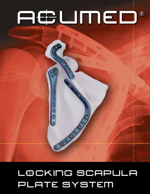
AcUMEDrLoCKING SCAPULAPLATE SYSTEM
LoCKING SCAPULAPLATE SYSTEMSince 1988 <strong>Acumed</strong> has beendesigning solutions to thedemanding situations facingorthopaedic surgeons, hospitalsand their patients. Ourstrategy has been to know theindication, design a solution tofit and deliver quality productsand instruments.The scapula plays an importantfunctional role by linking the upperextremity and the axial skeletonthrough its articulation of thesternoclavicular joint, the acromioclavicularjoint and the glenoid.<strong>Acumed</strong>’s Locking <strong>Scapula</strong> <strong>Plates</strong>are designed to provide excellentfixation for acute fractures,malunions and non-unions of thescapula.While often treated <strong>co</strong>nservatively,a portion of these displacedfractures can benefit from a lowprofile,<strong>co</strong>ngruent locking plate.Minimized soft tissue irritation aidswith patient rehabilitation and anearlier return to function.Indications<strong>Scapula</strong>r Body FracturesGlenoid Neck FracturesIntra-articular Glenoid Fractures<strong>Scapula</strong> Spine FracturesAcromial FracturesOs AcromialeBack support with locking technology.Fractures of the scapula are rare. The relative rarity of the moreseverely displaced injuries makes internal fixation of scapula fracturestechnically challenging. Anatomic <strong>co</strong>nstraints, particularly thescapula’s limited osseous anatomy, curved posterior surface andunique dimensions have <strong>co</strong>ntributed to the <strong>co</strong>mplexity of traditionaloperative treatment methods.With the introduction of the Locking <strong>Scapula</strong> Plate System,<strong>Acumed</strong> has taken locking technology one step further. Thedevelopment of these innovative implants improves the ability torestore functional normalcy to patients who have sustained displacedscapular fractures.Designed in <strong>co</strong>njunction with William B. Geissler M.D., <strong>Acumed</strong>’sindication-specific plates allow surgeons to choose a <strong>co</strong>nstructbased on their patients’ needs. The pre-<strong>co</strong>ntoured design eliminatesthe need to bend the plates to match the patient’s anatomyand better restores the functional angle of the shoulder joint. Thisdesign not only reduces OR time spent <strong>co</strong>ntouring a plate, butalso minimizes soft tissue irritation for the patient. The pre-<strong>co</strong>ntouredplates also help the surgeon reduce the fracture by actingas templates.2
Pre-<strong>co</strong>ntoured Plate Geometry matches theanatomy of the patient with little or no bending.The Locking <strong>Scapula</strong> <strong>Plates</strong> may also act as a guide ortemplate for restoring the patient’s original anatomywhen re<strong>co</strong>nstructing a severely displaced fracture, unliketraditional straight plates.Multiple Plate Options are available to fit a widevariety of scapula curvatures. The Medial and LateralBorder Plate(s) are frequently used for displaced scapulabody and glenoid neck fractures. The Glenoid Plate maybe selected for displaced intra-articular glenoid fractures.The Spine Plate is utilized for fractures along the spine aswell as fractures of the acromion.System Design Rationale was based on animproved understanding of the osseous regions thatprovide optimal implant placement and screw fixationfor internal fixation of scapula fractures. Regions ofsuperior scapula thickness suitable for internal fixationare located near the glenoid fossa, the medial and lateralborder and the scapula spine, including the acromion.RightLeftMedial Border<strong>Plates</strong>Intra-articularGlenoid <strong>Plates</strong>Lateral Border <strong>Plates</strong>Spine <strong>Plates</strong>3
MEDIAL/LATERAL BORDER PLATES Surgical TechniqueThis section offers <strong>Acumed</strong>’s suggested method for implanting the Medial and Lateral Border <strong>Scapula</strong> <strong>Plates</strong>. For specific questions notaddressed here, please <strong>co</strong>ntact your local <strong>Acumed</strong> representative or <strong>Acumed</strong> by phone at (888) 627.9957 or on the web at www.acumed.net.Step 1: Patient PositioningThe patient may be positioned in either the lateral decubitusposition or prone with the upper extremity draped free in theoperative field. This allows for manipulation of the upper extremityto aid with fracture reduction.Step 2: IncisionThe skin incision is made from the base of the acromion along theinferior margin of the scapula spine to the medial scapula border,then curved inferiorly to the inferior angle of the scapula. The dorsalfascia is then released along the lower edge of the scapula spineand the base of the acromion to improve visualization of the lateralscapula margin and neck of the scapula.STEP 3: DissectionStarting medially, elevate the rotator cuff musculature from theposterior aspect of the scapula, dissecting from medial to lateral witha periosteal elevator (MS-46212). The lateral border of the scapulaand neck of the scapula is then seen by reflecting the entire muscleflap laterally on its neurovascular pedicle.Step 4: ExposureThe inferior face of the scapula spine and body are then easilyvisualized. By careful subperiosteal dissection, the suprascapularnerve and artery and the circumflexed scapula artery are protected.The medial and lateral scapula margins are approximately 10-14mm thick, but are very dense <strong>co</strong>rtical bone which allows for goodpurchase with internal fixation.4
William B. Geissler, M.D.Step 5: Plate SelectionFor fractures of the scapula body, both the Medial and LateralBorder <strong>Plates</strong> are used to stabilize the fracture. These plates may beused in <strong>co</strong>njunction with one another or independently.The Medial Border Plate fits along the medial border of the scapulaand under the surface of the spine. The plate can be utilized to helpreduce the fracture back to the plate in cases where the scapularbody fracture is displaced. The appropriate sized left or right plate(s)are selected from the two different lengths provided. Usually thelarger 13-hole plates are ideal for most males and the 9-hole platesare best for smaller patients.Step 6: Plate Placement: Medial BorderFirst place the Medial Border Plate. The most lateral portion of theplate extends laterally to help stabilize glenoid neck fractures.Once the plate’s ideal position has been selected, it is provisionallyfixed to the scapula with bone clamps (PL-CL04). The fracturefragments may be manipulated directly by manipulation of the upperextremity which has been draped free, or by removing small fracturefragments in the center of the scapula and dissection anterior to thescapula.The Lateral Border Plate is useful for fractures involving the lateralborder and glenoid neck. The plate is placed along the lateral borderand extends proximally over the glenoid neck.Step 7: Non-Locking ScrewInsertion-Medial BorderThe non-locking screws may be placed uni<strong>co</strong>rtical or bi<strong>co</strong>rtical. Ifbi<strong>co</strong>rtical screws are used, it is important to not over-penetratethe far <strong>co</strong>rtex and potentially risk injury. Although 3.5mm screws(CO-3XX0) are re<strong>co</strong>mmended, optional 2.7mm (CO-27XX) and4.0mm (CA-4XX0) screws are available in the system. Using theappropriate drill size (MS-DC28 or MS-DC5020) and the drill guide(PL-2095), drill, measure for depth (MS-9022) and place the screwsinto the slots with the assembled driver. One screw should beplaced along the base of the scapula spine and another along themedial border. Once the two screws are installed, the bone clampsmay be removed.Step 8: Plate Placement: Lateral BorderWith the Medial Border Plate provisionally in place, the LateralBorder Plate is now selected. Once the plate’s ideal position hasbeen selected, it is provisionally fixed to the scapula with boneclamps (PL-CL04). The fracture fragments may be manipulateddirectly by manipulation of the upper extremity which has beendraped free, or by removing small fracture fragments in the centerof the scapula and dissection anterior to the scapula.5
William B. Geissler, M.D.Step 9: Non-Locking ScrewInsertion:Lateral BorderThe non-locking screws may be placed uni<strong>co</strong>rtical or bi<strong>co</strong>rtical. Ifbi<strong>co</strong>rtical screws are used, it is important to not over-penetrate thedistal <strong>co</strong>rtex and potentially risk injury. Although 3.5mm screws(CO-3XX0) are re<strong>co</strong>mmended, optional 2.7mm (CO-27XX) and4.0mm (CA-4XX0) screws are available in the system. One screwshould be placed in a slot along the lateral border, while another isplaced in the slot located over the glenoid. Once the two screwsare installed, the bone clamps may be removed.Step 10: Locking Screw InsertionUsing the locking drill guide (MS-LDG35) and the 2.8mm drill(MS-DC28), place the 3.5mm locking screws (COL-3XX0) into thethreaded holes so that there are at least three screws total(if possible) on each side of the fracture.Note: When placing the locking screws in the glenoid portion ofthe Lateral Border Plate, tapping (MS-LTT35) is re<strong>co</strong>mmended forpatients with dense bone. The drill guide (MS-LDG35) must beremoved prior to tapping.Step 11: Final AssessmentAn intraoperative radiograph is re<strong>co</strong>mmended to check theposition of the screws and the final reduction of the fracture. Themusculature is then re-approximated directly over the plate. Theskin is then closed in layers with a subcuticular stitch for theremaining skin layer.Post-op Proto<strong>co</strong>lThe patient is placed in an arm sling and starts pendulum range ofmotion exercises. Passive motion exercises are initiated from thefirst four weeks, active assisted from four to six weeks, and activestrengthening is initiated at six weeks post operatively once healing isseen radiographically.6
SCAPULA SPINE PLATE Surgical TechniqueThis section offers <strong>Acumed</strong>’s suggested method for implanting the <strong>Scapula</strong> Spine (Acromion) Plate. For specific questions not addressed here,please <strong>co</strong>ntact your local <strong>Acumed</strong> representative or <strong>Acumed</strong> at (888) 627.9957 or on the web at www.acumed.net.Step 1: Patient PositioningThe patient may be placed either in a beach chair position with abump under the scapula or the lateral decubitus position to exposefractures of the scapula, spine and acromion. The involved upperextremity is prepped and draped free to help manipulate thefracture fragments for reduction.Step 2: ExposureA horizontal incision is made directly over the palpable spine andthen curved anteriorly over the acromion. Dissection is sharplycarried down to the fascia where the skin flaps are elevated. Theorigin of the trapezium and deltoid may then be subperiosteallydissected to expose the fracture of the base of the spine and/oracromion.Step 3: Plate SelectionThe appropriate left or right <strong>Scapula</strong> Spine Plate is selected fromthe system. The plate is placed on the superior surface to stabilizefractures of the spine and/or acromion. In cases of non-union ormalunion, the curve of the plate can assist in anatomic reduction ofthe acromion.Step 4: Plate PlacementOnce the plate’s ideal positioning has been selected, it isprovisionally stabilized to the spine and/or acromion with boneclamps (PL-CL04).Note: The plate may be filled with locking or non-locking screwsdepending on the surgeon’s preference.7
William B. Geissler, M.D.Step 5: Non-Locking Screw InsertionThe non-locking screws may be placed uni<strong>co</strong>rtical or bi<strong>co</strong>rtical. Ifbi<strong>co</strong>rtical screws are used, it is important to not over-penetrate thedistal <strong>co</strong>rtex and potentially risk injury to the rotator cuff. Although3.5mm screws (CO-3XX0) are re<strong>co</strong>mmended, optional 2.7mm(CO-27XX) and 4.0mm (CA-4XX0) screws are available in thesystem. Using the appropriate drill size (MS-DC28 or MS-DC5020)and the drill guide (PL-2095), drill, measure for depth (MS-9022) andplace the screws into the slots with the assembled driver. Once thetwo screws are installed, the bone clamp(s) may be removed.Step 6: Locking Screw InsertionUsing the locking drill guide (MS-LDG35) and the 2.8mm drill(MS-DC28), place the 3.5mm locking screws (COL-3XX0) into thethreaded holes so that there are at least three screws total (ifpossible) on each side of the fracture.Step 7: Final AssessmentAn intraoperative radiograph is re<strong>co</strong>mmended to check theposition of the screws and the final reduction of the fracture. Themusculature is then re-approximated directly over the plate. Theskin is then closed in layers with a subcuticular stitch for theremaining skin layer.Post-op Proto<strong>co</strong>lThe patient is placed in an arm sling and starts pendulum range ofmotion exercises. Passive motion exercises are initiated from thefirst four weeks, active assisted from four to six weeks and activestrengthening is initiated at six weeks post operatively once healing isseen radiographically.8
INTRA-ARTICULAR GLENOID PLATES Surgical TechniqueThis section offers <strong>Acumed</strong>’s suggested method for implanting the Intra-articular Glenoid Plate. For specific questions not addressed here,please <strong>co</strong>ntact your local <strong>Acumed</strong> representative or <strong>Acumed</strong> at (888) 627.9957 or at www.acumed.netStep 1: Patient PositioningThe patient is placed in the lateral decubitus position and theinvolved upper extremity is draped out to help facilitate reductionof the fracture fragments.Step 2: IncisionA vertical incision is made from the scapula spine over theglenohumeral joint. The deltoid origin is then teed off the scapulaspine and split. Be careful not to extend the incision too distal andaffect the axillary nerve. Alternatively, a horizontal incision is madeover the spine and the deltoid is released.Step 3: DissectionBlunt dissection is then <strong>co</strong>ntinued between the infraspinatus andteres minor muscles. This plane may be difficult to define initially.The infraspinatus muscle is retracted superiorly and the teres minormuscle is retracted inferiorly to expose the posterior regions of theglenoid cavity in the neck of the scapula.Step 4: ExposureThe posterior capsule is then opened in a “T” fashion. An incision ismade vertically from the humeral head to the glenoid, and then theincision is carried proximally and distally along the glenoid neck toexpose the intra-articular fracture.9
William B. Geissler, M.D.Step 5: Plate Selection and PlacementThe appropriate left or right Glenoid Plate is selected from thesystem. The plate is placed on the superior surface to stabilizefractures of the posterior margin of the glenoid and anyintra-articular fragments.Once the plate’s ideal positioning has been selected, it isprovisionally stabilized to the glenoid with bone clamps (PL-CL04).The plate may be filled with locking or non-locking screwsdepending on the surgeon’s preference.Step 6: Non-Locking Screw InsertionThe non-locking screws may be placed uni<strong>co</strong>rtical or bi<strong>co</strong>rtical.Although 3.5mm screws (CO-3XX0) are re<strong>co</strong>mmended, optional2.7mm (CO-27XX) and 4.0mm (CA-4XX0) screws areavailable in the system. Using the appropriate drill size (MS-DC28or MS-DC5020) and the drill guide (PL-2095), drill, measure fordepth (MS-9022) and place the screws into the slots with theassembled driver. Once the two screws are installed, the boneclamp(s) may be removed.Step 7: Locking Screw InsertionUsing the locking drill guide (MS-LDG35) and the 2.8mm drill(MS-DC28), place the 3.5mm locking screws (COL-3XX0) into thethreaded holes.Note: Tapping (MS-LTT35) is re<strong>co</strong>mmended for patients with densebone. The drill guide (MS-LDG35) must be removed prior to tapping.Step 8: Final AssessmentAn intraoperative radiograph is re<strong>co</strong>mmended to check the positionof the screws and the final reduction of the fracture. The musculatureis then re-approximated directly over the plate. The skin is thenclosed in layers with a subcuticular stitch for the remaining skin layer.Post-op Proto<strong>co</strong>lThe patient is placed in an arm sling and starts pendulum range of motion exercises. Passive motion exercises are initiated from the firstfour weeks, active assisted from four to six weeks, and active strengthening is initiated at six weeks post operatively, once healing is seenradiographically.10
ORDERING INFORMATIONLocking <strong>Scapula</strong> <strong>Plates</strong>3.5mm Locking Screws3.5mm Non-Locking Screws4-hole Glenoid Plate, LeftPL-SG04L3.5mm x 8mm Locking Cortical ScrewCOL-30803.5mm x 8mm Cortical ScrewCO-30804-hole Glenoid Plate, RightPL-SG04R3.5mm x 10mm Locking Cortical ScrewCOL-31003.5mm x 10mm Cortical ScrewCO-31006-hole <strong>Scapula</strong> Spine Plate, LeftPL-SA06L3.5mm x 12mm Locking Cortical ScrewCOL-31203.5mm x 12mm Cortical ScrewCO-31206-hole <strong>Scapula</strong> Spine Plate, RightPL-SA06R3.5mm x 14mm Locking Cortical ScrewCOL-31403.5mm x 14mm Cortical ScrewCO-314010-hole <strong>Scapula</strong> Lateral Border Plate, LeftPL-SLB10L3.5mm x 16mm Locking Cortical ScrewCOL-31603.5mm x 16mm Cortical ScrewCO-316010-hole <strong>Scapula</strong> Lateral Border Plate, RightPL-SLB10R3.5mm x 18mm Locking Cortical ScrewCOL-31803.5mm x 18mm Cortical ScrewCO-31809-hole <strong>Scapula</strong> Medial Border Plate, LeftPL-SMB09L3.5mm x 20mm Locking Cortical ScrewCOL-32003.5mm x 20mm Cortical ScrewCO-32009-hole <strong>Scapula</strong> Medial Border Plate, RightPL-SMB09R3.5mm x 22mm Locking Cortical ScrewCOL-32203.5mm x 22mm Cortical ScrewCO-322013-hole <strong>Scapula</strong> Medial Border Plate, LeftPL-SMB13L3.5mm x 24mm Locking Cortical ScrewCOL-32403.5mm x 24mm Cortical ScrewCO-324013-hole <strong>Scapula</strong> Medial Border Plate, RightPL-SMB13R3.5mm x 26mm Locking Cortical ScrewCOL-32603.5mm x 26mm Cortical ScrewCO-3260Instruments3.5mm x 28mm Locking Cortical Screw3.5mm x 30mm Locking Cortical ScrewCOL-3280COL-33003.5mm x 28mm Cortical Screw3.5mm x 30mm Cortical ScrewCO-3280CO-3300.045" Guide Wire SS 6" WS-1106ST3.5mm x 32mm Locking Cortical ScrewCOL-33203.5mm x 32mm Cortical ScrewCO-3320.059" Guide Wire SS 6" WS-1505ST3.5mm x 34mm Locking Cortical ScrewCOL-33403.5mm x 34mm Cortical ScrewCO-3340Plate BenderPL-20403.5mm x 36mm Locking Cortical ScrewCOL-33603.5mm x 36mm Cortical ScrewCO-3360Large Plate BenderPL-20453.5mm x 38mm Locking Cortical ScrewCOL-33803.5mm x 38mm Cortical ScrewCO-33802.0/2.8 Narrow Drill Guide PL-21183.5mm x 40mm Locking Cortical ScrewCOL-34003.5mm x 40mm Cortical ScrewCO-34002.8/3.5 Narrow Drill Guide PL-21963.5mm x 45mm Locking Cortical ScrewCOL-34503.5mm x 45mm Cortical ScrewCO-3450Offset Drill GuidePL-20953.5mm x 50mm Locking Cortical ScrewCOL-35003.5mm x 50mm Cortical ScrewCO-35002.7mm Long Tap TipMS-LTT273.5mm x 55mm Locking Cortical ScrewCOL-35503.5mm x 55mm Cortical ScrewCO-35503.5mm Long Tap TipMS-LTT353.5mm x 60mm Locking Cortical ScrewCOL-36003.5mm x 60mm Cortical ScrewCO-36002.0mm Quick Release DrillMS-DC50203.5mm x 65mm Locking Cortical ScrewCOL-36503.5mm x 65mm Cortical ScrewCO-36502.8mm Quick Release Drill3.5mm Quick Release DrillDepth GaugeLarge Cannulated Quick Release DriverHandle2.5mm Quick Release Driver TipScrew Sleeve2.7mm Locking Drill Guide3.5mm Locking Drill GuidePlate TackQuick Release Driver HandleFreer ElevatorReduction Forceps w. Serrated JawSmall Pointed Reduction ForcepsHohman RetractorPeriosteal Elevator<strong>Scapula</strong> Plate Insert AssemblyMS-DC28MS-DC35MS-9022MS-3200HPC-0025MS-SS35MS-LDG27MS-LDG35PL-PTACKMS-1210MS-57614PL-CL04OW-1200MS-46827MS-46212Universal Tray <strong>Scapula</strong> Plate Insert Base 80-0136Universal Tray <strong>Scapula</strong> Plate Insert Lid 80-0137Universal Tray <strong>Scapula</strong> Plate Tray InsertAssembly80-01352.7mm Locking Screws2.7mm x 8mm Locking Cortical Screw COL-20802.7mm x 10mm Locking Cortical Screw COL-21002.7mm x 12mm Locking Cortical Screw COL-21202.7mm x 14mm Locking Cortical Screw COL-21402.7mm x 16mm Locking Cortical Screw COL-21602.7mm x 18mm Locking Cortical Screw COL-21802.7mm x 20mm Locking Cortical Screw COL-22002.7mm x 22mm Locking Cortical Screw COL-22202.7mm Non-Locking Screws2.7mm x 8mm Cortical ScrewCO-27082.7mm x 10mm Cortical ScrewCO-27102.7mm x 12mm Cortical ScrewCO-27122.7mm x 14mm Cortical ScrewCO-27142.7mm x 16mm Cortical ScrewCO-27162.7mm x 18mm Cortical ScrewCO-27182.7mm x 20mm Cortical ScrewCO-27202.7mm x 22mm Cortical ScrewCO-27222.7mm x 24mm Cortical ScrewCO-27242.7mm x 26mm Cortical ScrewCO-27264.0mm Cancellous Screws4.0mm x 12mm Cancellous Screw4.0mm x 14mm Cancellous Screw4.0mm x 16mm Cancellous Screw4.0mm x 18mm Cancellous Screw4.0mm x 20mm Cancellous Screw4.0mm x 22mm Cancellous Screw4.0mm x 24mm Cancellous Screw4.0mm x 28mm Cancellous Screw4.0mm x 30mm Cancellous Screw4.0mm x 35mm Cancellous Screw4.0mm x 40mm Cancellous Screw4.0mm x 45mm Cancellous Screw4.0mm x 50mm Cancellous Screw4.0mm x 55mm Cancellous Screw4.0mm x 60mm Cancellous ScrewCA-4120CA-4140CA-4160CA-4180CA-4200CA-4220CA-4240CA-4280CA-4300CA-4350CA-4400CA-4450CA-4500CA-4550CA-46002.7mm x 28mm Cortical Screw2.7mm x 30mm Cortical Screw2.7mm x 34mm Cortical Screw2.7mm x 40mm Cortical ScrewCO-2728CO-2730CO-2734CO-274011
AcUMEDr5885 N.W. Cornelius Pass RoadHillsboro, OR 97124(888) 627-9957www.acumed.netEffective 11/2008CPS00-11-A