Ascension Modular Radial Head - PerPrima
Ascension Modular Radial Head - PerPrima
Ascension Modular Radial Head - PerPrima

Create successful ePaper yourself
Turn your PDF publications into a flip-book with our unique Google optimized e-Paper software.
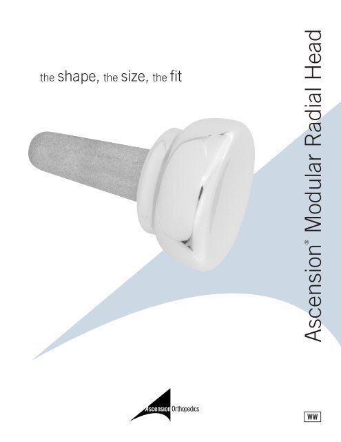
the shape, the size, the fit<strong>Ascension</strong>® <strong>Modular</strong> <strong>Radial</strong> <strong>Head</strong>WW
anatomicdesign➤➤➤stem and head sizes to fit your indications and patient anatomyarticular friendly shape – reduces edge loading on thecapitellum and radial notch allowsfor annular ligament closurecementlessRadiopaque prosthesesallow for intraoperativeverification of implantposition and postoperative assessment.➤➤➤Bone removal is minimizedCritical soft tissue structuresare preservedAlignment Awl and Guidesprovide accurate visualreference along the boneaxis promoting restorationof anatomic bone alignmentsimplifiedinstrumentation➤➤simplified instruments provide a reproducible outcomein-wound or back table assembly optionIn Situ Assembly Instruments:Stem Holder and<strong>Head</strong> ImpactorBack Table Assembly Instruments:Stem Impactor andAssembly Plate
surgical techniqueFIGURE 1The Initial Incisionand Capsular ExposureExpose the radial capitellar joint using the Kocherapproach through the interval between the anconeusand extensor carpi ulnaris muscles. Make a 6-7cmincision centered on the radial head Figure 1.Pronate the forearm during exposure to protect themotor branch of the radial nerve that passes aroundthe radial neck. If needed, release the origin of theanconeus subperiostally and retract it posteriorlyto permit adequate exposure of the capsule.Continue the dissection to the joint capsule. Dividethe annular ligament (AL) and radial collateralligaments (RCL) longitudinally along the centerlineof the head. Reflect the lateral capsule anteriorlyand posteriorly to expose the radial head Figure 2.Resecting the <strong>Radial</strong> <strong>Head</strong>Two methods may be used to assist in resectingthe radial head.<strong>Radial</strong> <strong>Head</strong> Resection Guide:The radial head resection guide has two resectionlevels. Inspection of the radial head and trauma tothe neck will determine if the standard or longradial head implant will be used. Prior templatingof the x-ray will also assist in determining whichradial head will be used. Use the normal or long<strong>Radial</strong> <strong>Head</strong> Resection Guide to mark the level ofthe resection Figure 3.With one edge of the guide resting on the capitellum,use a surgical marker to mark the resection lineon the neck of the radius by resting the tip of themarker against the distal side of the guide whilerotating the forearm through supination-pronation.The resulting line should mark a plane that isperpendicular to the pronation-supination axis ofthe forearm. Resect the head holding the saw bladeperpendicular to the axis of rotation. Reinsert theguide between the capitellum and the resection toensure a perpendicular cut Figure 4.FIGURE 2FIGURE 3FIGURE 4
External Resection GuideThe external resection guide is intended todetermine the correct resection level and orientationwith respect to the pronation/supination axis of theforearm. With the proximal edge of the resectionguide placed against the capitellum and restingon the neck of the radius, align the distal end ofthe rod with the styloid process of the ulna. Afterdetermining whether the standard or long radialhead implant will be used, use a surgical markerto mark the level of resection of the head. After thelevel has been marked remove the guide. Resectthe head holding the saw blade perpendicular tothe axis of rotation. The resulting cut should be ina plane that is perpendicular to the pronationsupinationaxis of the forearm.FIGURE 5FIGURE 6Intramedullary Preparationfor Trial SizersThe medullary canal is now prepared for insertionof the Trial Sizers, which are used to select theimplant size. Enter the canal with the Starter Awlusing a twisting motion Figure 5.The Starter Awl should be inserted only 2 cm. TheTrial Sizer has an undersized stem for ease of trialinsertion and to maintain the integrity of themedullary canal for the final press fit of the implant.FIGURE 7Trial ReductionSelect the Trial closest in size to, but not largerthan, the resected head. Insert the Trial stem intothe hole created by the Starter Awl Figure 6.Assess elbow stability and tracking in forearmflexion, extension and rotation. An osteotomy thatis poorly-aligned will cause the Trial to be unstableduring the assessment. Be sure to coapt or slightlyoverlap the dissected capsule edges (previouslyreflected anteriorly and posteriorly) to assess the fitof the AL around the head of the Sizer. The edgesshould meet easily. If the AL cannot wrap completelyaround the Sizer, a smaller implant is preferred.FIGURE 8Broach the CanalOnce the implant size has been determined, removethe Trial and broach the canal to the selected sizeFigure 7.
Broach progressively up to the selected implantsize starting with the smallest size broach. Thebroach should be aligned with the pronationsupinationaxis, perpendicular to the resection.FIGURE 9Assembly and ImplantationThere are two options to assemble the stem-headcomponents.OR Back Table AssemblyUsing the back table assembly plate, place thecorrect size head on the back table assemblyplate. The morse taper of the implant stem isinserted into the implant head taper. Place thestem impactor over the stem. The implant taperis seated by firm impaction with a mallet.FIGURE 10Using finger control, insert the prosthesis steminto the prepared hole. It may be necessary toretract the radius to access the canal and allowthe head to clear the capitellum. Using the headimpactor provided, impact the implant until thecollar abuts the osteotomy Figure 8.In Situ AssemblyThe <strong>Ascension</strong> <strong>Modular</strong> <strong>Radial</strong> <strong>Head</strong> can beassembled in situ. Place the correct size steminto the prepared medullary canal of the radius.Place the stem holder instrument around the collarof the stem. Using the stem impactor instrument,impact the stem into the canal until it is flushwith the osteotomy Figure 9. Place the head componenton the morse taper of the stem Figure 10.Seat the implant taper with firm impaction usingthe head impactor Figure 11. Remove the stemholder and impact the implant until flush withthe osteotomy.FIGURE 11FIGURE 12ClosureRepair the AL and RCL Figure 12.Repair the fascial interval connecting anconeusand extensor carpi ulnaris muscles. Close theskin. Splint the elbow at 90° flexion and inneutral to full pronation.
<strong>Ascension</strong> ®<strong>Modular</strong> <strong>Radial</strong> <strong>Head</strong>Multiple head/stem sizes andconfigurations accommodate abroad range of patient anatomySIZE / COMPONENTCATALOG NUMBERCATALOG NUMBER20mm long headMRH-350-20LInstrument SetINS-350-0022mm long headMRH-350-22L24mm long headMRH-350-24L20mm standard headMRH-350-20S22mm standard headMRH-350-22S24mm standard headMRH-350-24S01 standard stem MRH-350-0102 standard stem MRH-350-0203 standard stem MRH-350-0304 long stem MRH-350-04ASCENSION ORTHOPEDICS, INC.8200 CAMERON ROAD, SUITE C140AUSTIN, TEXAS 78754-3832512.836.5001 512.836.6933 faxCUSTOMER SERVICE: 877.370.5001 (toll-free in U.S.)customerservice@ascensionortho.comwww.ascensionortho.comCaution: U.S. federal law restricts this deviceto sale by or on the order of a physician.LC-04-357-003 rev C©2004WW