9 Contact Stresses
9 Contact Stresses
9 Contact Stresses

You also want an ePaper? Increase the reach of your titles
YUMPU automatically turns print PDFs into web optimized ePapers that Google loves.
9.2 HERTZIAN CONTACT STRESSES 417<br />
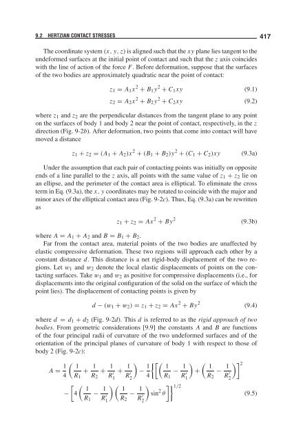
The coordinate system (x, y, z) is aligned such that the xy plane lies tangent to the<br />
undeformed surfaces at the initial point of contact and such that the z axis coincides<br />
with the line of action of the force F. Before deformation, suppose that the surfaces<br />
of the two bodies are approximately quadratic near the point of contact:<br />
z1 = A1x 2 + B1y 2 + C1xy (9.1)<br />
z2 = A2x 2 + B2y 2 + C2xy (9.2)<br />
where z1 and z2 are the perpendicular distances from the tangent plane to any point<br />
on the surfaces of body 1 and body 2 near the point of contact, respectively, in the z<br />
direction (Fig. 9-2b). After deformation, two points that come into contact will have<br />
moved a distance<br />
z1 + z2 = (A1 + A2)x 2 + (B1 + B2)y 2 + (C1 + C2)xy (9.3a)<br />
Under the assumption that each pair of contacting points was initially on opposite<br />
ends of a line parallel to the z axis, all points with the same value of z1 + z2 lie on<br />
an ellipse, and the perimeter of the contact area is elliptical. To eliminate the cross<br />
term in Eq. (9.3a), the x, y coordinates may be rotated to coincide with the major and<br />
minor axes of the elliptical contact area (Fig. 9-2c). Thus, Eq. (9.3a) can be rewritten<br />
as<br />
z1 + z2 = Ax 2 + By 2<br />
(9.3b)<br />
where A = A1 + A2 and B = B1 + B2.<br />
Far from the contact area, material points of the two bodies are unaffected by<br />
elastic compressive deformation. These two regions will approach each other by a<br />
constant distance d. This distance is a net rigid-body displacement of the two regions.<br />
Let w1 and w2 denote the local elastic displacements of points on the contacting<br />
surfaces. Take w1 and w2 as positive for compressive displacements (i.e., for<br />
displacements into the original configuration of the solid on the surface of which the<br />
point lies). The displacement of contacting points is given by<br />
d − (w1 + w2) = z1 + z2 = Ax 2 + By 2<br />
(9.4)<br />
where d = d1 + d2 (Fig. 9-2d). This d is referred to as the rigid approach of two<br />
bodies. From geometric considerations [9.9] the constants A and B are functions<br />
of the four principal radii of curvature of the two undeformed surfaces and of the<br />
orientation of the principal planes of curvature of body 1 with respect to those of<br />
body 2 (Fig. 9-2c):<br />
A = 1<br />
<br />
1<br />
+<br />
4 R1<br />
1<br />
+<br />
R2<br />
1<br />
−<br />
<br />
4<br />
1<br />
R1<br />
− 1<br />
R ′ 1<br />
R ′ 1<br />
+ 1<br />
R ′ <br />
−<br />
2<br />
1<br />
4<br />
1<br />
R2<br />
− 1<br />
R ′ 2<br />
1<br />
<br />
sin 2 θ<br />
R1<br />
1/2 − 1<br />
R ′ <br />
1<br />
+ −<br />
1<br />
R2<br />
1<br />
R ′ 2 2<br />
(9.5)