H-1100 - Smiths Medical
H-1100 - Smiths Medical
H-1100 - Smiths Medical

You also want an ePaper? Increase the reach of your titles
YUMPU automatically turns print PDFs into web optimized ePapers that Google loves.
Manufacturer:<br />
<strong>Smiths</strong> <strong>Medical</strong> ASD, Inc.<br />
160 Weymouth Street<br />
Rockland, MA 02370, USA<br />
USA/Canada: 1-800-258-5361<br />
International: +1-781-878-8011<br />
Made in USA<br />
Australian Representative:<br />
<strong>Smiths</strong> <strong>Medical</strong> Australasia Pty. Ltd.<br />
61 Brandl Street<br />
Eight Mile Plains, QLD 4113, Australia<br />
Tel AU: +61 (0) 7 3340 1300<br />
Tel NZ: 0 800 444 200<br />
lTM<br />
European Representative:<br />
<strong>Smiths</strong> <strong>Medical</strong> International Ltd.<br />
Colonial Way<br />
Watford, Herts, WD24 4LG, UK<br />
Tel: +44 (0) 1923 246434<br />
www.smiths-medical.com<br />
s<br />
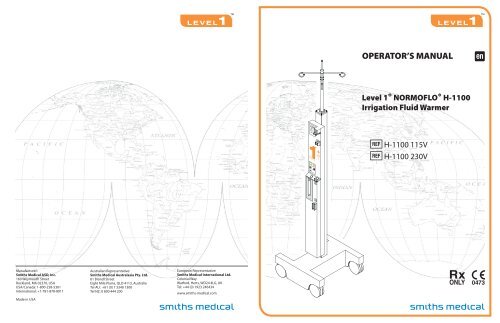
OPERATOR’S MANUAL<br />
Level 1® NORMOFLO® H-<strong>1100</strong><br />
Irrigation Fluid Warmer<br />
< H-<strong>1100</strong> 115V<br />
< H-<strong>1100</strong> 230V<br />
lTM<br />
6 2<br />
s
lTM<br />
Level 1 ® NORMOFLO ® H-<strong>1100</strong><br />
Irrigation Fluid Warmer<br />
< H-<strong>1100</strong> 115V<br />
< H-<strong>1100</strong> 230V<br />
OPERATOR’S MANUAL<br />
P/N 4533802-EN Rev. 004
Level 1 ® NORMOFLO ® H-<strong>1100</strong> Irrigation Fluid Warmer Operator’s Manual<br />
Part Number: 4533802-EN Rev. 004 (2007-08)<br />
This revision supercedes all previous revisions.<br />
ii Level 1 ® NORMOFLO ® H-<strong>1100</strong> Irrigation Fluid Warmer | Operator’s Manual<br />
C o p y r i g h t<br />
Every effort has been made to ensure that the information in this manual is accurate and details provided<br />
are correct at the time of printing. The company, however, reserves the right to improve the equipment<br />
shown. Mention of third-party products is for informational purposes only and constitutes neither an<br />
endorsement nor a recommendation. <strong>Smiths</strong> <strong>Medical</strong> ASD Inc. (“<strong>Smiths</strong> <strong>Medical</strong>”) assumes no<br />
responsibility with regard to the performance or use of these products.<br />
Level 1, NORMOFLO, and Level 1 and <strong>Smiths</strong> <strong>Medical</strong> design marks are trademarks of the <strong>Smiths</strong> <strong>Medical</strong><br />
family of companies. The symbol ® indicates the trademark is registered in the U.S. Patent and Trademark<br />
office and certain other countries.<br />
All other names and marks mentioned are the trade names, trademarks, or service marks of the respective<br />
owners.<br />
The products described are covered by one or more of the following U.S. Patent Nos. 4,759,749;<br />
4,878,537; 4,900,308; 5,063,994; 5,097,898; 5,417,274 and 5,512,043.<br />
For further information, please call your local <strong>Smiths</strong> <strong>Medical</strong> representative or <strong>Smiths</strong> <strong>Medical</strong> direct at<br />
1-800-258-5361 or +1-781-878-8011.<br />
©2007 <strong>Smiths</strong> <strong>Medical</strong> family of companies. All rights reserved.
Contents<br />
1 About this Manual 1<br />
Conventions Used in this Manual 1<br />
2 Description 2<br />
Gas Vent 2<br />
Temperature Control 2<br />
Automatically Operating Pole 2<br />
3 Indications for Use 3<br />
4 Important Safety Information 4<br />
5 Out of the Box-Assembly 7<br />
Step 1 - Verify Components of the Fluid Warmer 8<br />
Step 2 - Assemble Fluid Warmer to Base 9<br />
Step 3 - Attach the Fluid Bag Hanger 10<br />
Step 4 - Disinfect the Recirculating Solution Reservoir 10<br />
Step 5 - Preparation for Use 11<br />
Step 6 - Perform Electrical Safety Tests 11<br />
6 Principle of Operation 12<br />
Fluid Warming 12<br />
7 Controls and Displays 14<br />
Fluid Warmer Power and Alarm Test Panel 15<br />
Fluid Warmer Display Panel 16<br />
Reservoir Level Display 16<br />
Interlocks 17<br />
8 Operation 18<br />
OFF Mode 20<br />
ON/Automatic Operation Mode for Fluid Warmer 20<br />
Alarm Test Mode 21<br />
Over Temperature Test Mode 21<br />
Temperature Display 21<br />
Check Disposables Mode 22<br />
Add Recirculating Solution Mode 22<br />
Over Temperature Alarm Mode 23<br />
9 Operating Instructions 24<br />
9.1 Set Up for Use 25<br />
9.2 Use of the Fluid Warmer 28<br />
C o n t e n t s<br />
Level 1 ® NORMOFLO ® H-<strong>1100</strong> Irrigation Fluid Warmer | Operator’s Manual iii
C o n t e n t s<br />
9.3 After Use 29<br />
10 Troubleshooting 30<br />
General Troubleshooting Guide 30<br />
Slow Flow Rate Troubleshooting 31<br />
11 Testing 32<br />
Add Recirculating Solution Alarm 32<br />
Check Disposables Alarm 32<br />
Over Temperature Test 33<br />
Fluid Warmer Alarm Signal Test 33<br />
Performance Testing 34<br />
Periodic Electrical Testing 36<br />
12 Maintenance 37<br />
Maintenance Performed with Every Use 37<br />
Maintenance Performed Every 30 Days 37<br />
Maintenance Performed Every 12 Months 38<br />
Maintenance and Calibration Log 40<br />
13 Limited Warranty 41<br />
14 Service 43<br />
Warranty Service 43<br />
Non-Warranty Work 43<br />
Additional Documentation 43<br />
Disposal Information 44<br />
Service Contacts 44<br />
15 Specifications 45<br />
System Specifications 45<br />
Electromagnetic Environmental Recommendations<br />
Level 1<br />
46<br />
® NORMOFLO ® Irrigation Warming Sets<br />
(Disposable Sets) 46<br />
Disposable Set Accessories 46<br />
16 Symbols 47<br />
iv Level 1 ® NORMOFLO ® H-<strong>1100</strong> Irrigation Fluid Warmer | Operator’s Manual
SECTION 1<br />
About this Manual<br />
S E C T I O N 1 • A b o u t t h i s M a n u a l<br />
This Operator's Manual describes the set-up, use, and maintenance of the<br />
Level 1 ® NORMOFLO ® H-<strong>1100</strong> Irrigation Fluid Warmer.<br />
These instructions contain important information for safe use of<br />
the product. Read the entire operator’s manual, including<br />
Warnings and Cautions, before using the product. Failure to<br />
properly follow warnings, cautions, and instructions could result<br />
in death or serious injury to the patient.<br />
The manual is intended for use by individuals trained in the healthcare<br />
and biomedical professions.<br />
WARNING<br />
• Read and follow all instructions, labeling, and accompanying<br />
documents supplied with this medical device. Failure to follow<br />
instructions, including all warnings and cautions could result in<br />
death or serious injury to the patient or user.<br />
Conventions Used in this Manual<br />
Convention Description<br />
Note A Note statement alerts the user to important<br />
information that requires attention.<br />
CAUTION A Caution statement alerts the user to conditions<br />
that may cause physical injury and/or an adverse<br />
effect on the device or its performance.<br />
WARNING A Warning statement alerts the user to conditions<br />
that may cause serious personal injury or death<br />
to the user or patient.<br />
Level 1 ® NORMOFLO ® H-<strong>1100</strong> Irrigation Fluid Warmer | Operator’s Manual 1
SECTION 2<br />
Description<br />
The Level 1 ® NORMOFLO ® H-<strong>1100</strong> Irrigation Fluid Warmer has been<br />
designed for safe, rapid, in-line warming of irrigating fluids as they are<br />
administered to patients. This non-invasive method employs single-use,<br />
disposable, irrigating sets that include a Heat Exchanger and may include a<br />
Gas Vent.<br />
Gas Vent<br />
Some Level 1 ® NORMOFLO ® Irrigation Warming Sets (Disposable<br />
Sets) include a Gas Vent. The Gas Vent releases micro-bubbles of gas<br />
from fluids as they are warmed.<br />
Temperature Control<br />
The Level 1 ® NORMOFLO ® H-<strong>1100</strong> Irrigation Fluid Warmer employs<br />
a safe recirculating solution heating system, inherently free of any “hot<br />
spots.” The primary temperature control circuit sets the recirculating<br />
solution to a temperature of approximately 41.7°C for efficient heat<br />
exchange and maximum fluid warming.<br />
Automatically Operating Pole<br />
The Level 1 ® NORMOFLO ® H-<strong>1100</strong> Irrigation Fluid Warmer includes<br />
an electronically operated pole that lifts fluid bags with the touch of a<br />
switch.<br />
Level 1 ® NORMOFLO ® Irrigation Warming Sets<br />
Disposable Sets available for use on the Level 1 ® NORMOFLO ®<br />
H-<strong>1100</strong> Irrigation Fluid Warmer are listed below.<br />
• IR-40<br />
• IR-500<br />
• IR-600<br />
• IRI-600<br />
• IRI-600B<br />
• IR-700<br />
The IRI-600, IRI-600B, and IR-700 are CE-marked products.<br />
2 Level 1 ® NORMOFLO ® H-<strong>1100</strong> Irrigation Fluid Warmer | Operator’s Manual<br />
S E C T I O N 2 • D e s c r i p t i o n
SECTION 3<br />
Indications for Use<br />
S E C T I O N 3 • I n d i c a t i o n s f o r U s e<br />
The Level 1 ® NORMOFLO ® H-<strong>1100</strong> Irrigation Fluid Warmer (Fluid<br />
Warmer) is designed for use by trained medical personnel for in-line<br />
warming of irrigating fluids.<br />
Level 1 ® NORMOFLO ® H-<strong>1100</strong> Irrigation Fluid Warmer | Operator’s Manual 3
SECTION 4<br />
Important Safety Information<br />
This section covers information for prescribers and guidelines for safe use<br />
of the Level 1 ® NORMOFLO ® H-<strong>1100</strong> Irrigation Fluid Warmer (Fluid<br />
Warmer).<br />
WARNINGS<br />
Death or serious injury may occur to the patient or user if these<br />
warnings are not followed:<br />
S E C T I O N 4 • I m p o r t a n t S a f e t y I n f o r m a t i o n<br />
• Read and follow all instructions, labeling, and accompanying<br />
documents supplied with this medical device. Failure to follow<br />
instructions, including all warnings and cautions, could result in<br />
death or serious injury to the patient or user.<br />
• Do not use the Fluid Warmer in high-energy fields such as: MRI,<br />
X-RAY, portable and mobile RF communications equipment, and<br />
other such devices. The Fluid Warmer may act as a projectile in<br />
a strong magnetic field, cause image artifacts, or not function<br />
as intended.<br />
• Do not bend the heat exchanger. Bending may damage the<br />
heat exchanger allowing communication between the<br />
recirculating solution and irrigation fluid path, resulting in the<br />
delivery of inappropriate fluids.<br />
• Exposed conductor on MAINS power cord can cause an<br />
electrocution hazard. Remove device from service if MAINS<br />
power cord has exposed wires.<br />
• Activation of the Over Temperature warning signal indicates<br />
that warming has stopped and immediate operator intervention<br />
is required. Failure to clear the over temperature condition or to<br />
take the device out of service may result in death or serious<br />
injury to the patient.<br />
Continued<br />
4 Level 1 ® NORMOFLO ® H-<strong>1100</strong> Irrigation Fluid Warmer | Operator’s Manual
S E C T I O N 4 • I m p o r t a n t S a f e t y I n f o r m a t i o n<br />
WARNINGS<br />
Continued from previous page<br />
• The Fluid Warmer is for use only with <strong>Smiths</strong> <strong>Medical</strong> supplied<br />
or approved parts, accessories, and Irrigation Disposable Sets.<br />
The device may not function as intended with the use of<br />
unapproved parts, accessories, or Disposable Sets.<br />
• Grounding reliability can only be achieved when MAINS power<br />
cords are connected to a properly grounded receptacle. Risk of<br />
electrical shock exists if the equipment is not connected to a<br />
properly grounded receptacle.<br />
• If any visual indicator does not illuminate or the audible signal<br />
does not sound, do not use the Fluid Warmer. Remove the<br />
device from service immediately.<br />
• Do not operate the Fluid Warmer in the presence of a<br />
flammable anesthetic mixture with air, oxygen, or nitrous<br />
oxide.The risk of explosion exists if the Fluid Warmer is operated<br />
in a potentially explosive environment.<br />
• No user-serviceable parts. All service must be performed by<br />
<strong>Smiths</strong> <strong>Medical</strong> or an authorized representative.<br />
• Disposable Sets are supplied with a sterile fluid path which may<br />
be compromised if the caps are not in place. Do not use<br />
Disposable Set if spike caps and end caps are not securely in<br />
place, or if connections are not secure as the fluid path may not<br />
be sterile and may cause death or serious injury to the patient.<br />
• Disposable Sets are for single use only. To reduce the risk of<br />
cross contamination, do not reuse Disposable Sets.<br />
• Do not overextend Automatic Pole; if Automatic Pole is<br />
overextended the Fluid Warmer may become unstable.<br />
Level 1 ® NORMOFLO ® H-<strong>1100</strong> Irrigation Fluid Warmer | Operator’s Manual 5
CAUTIONS<br />
Physical injury to the patient, user, and/or an adverse effect on the<br />
device or its performance may occur if these cautions are not<br />
followed:<br />
• Do not use the Fluid Warmer if equipment or Disposable Set<br />
malfunction is evident.<br />
• Avoid contact with surgical lights or other overhead fixtures.<br />
Maximum Transport Load: 12 liters at maximum height of 2.25<br />
meters (7 ft 4 inch), 6 liters at maximum height of 2.54 meters<br />
(8 ft 4 inch) from floor to bag hanger.<br />
• Federal law (U.S.A.) restricts this device to sale by or on the<br />
order of a physician.<br />
S E C T I O N 4 • I m p o r t a n t S a f e t y I n f o r m a t i o n<br />
6 Level 1 ® NORMOFLO ® H-<strong>1100</strong> Irrigation Fluid Warmer | Operator’s Manual
SECTION 5<br />
S E C T I O N 5 • O u t o f t h e B o x - A s s e m b l y<br />
Out of the Box-Assembly<br />
This device must be assembled and tested by authorized <strong>Smiths</strong> <strong>Medical</strong><br />
personnel, an authorized distributor of <strong>Smiths</strong> <strong>Medical</strong>, or a qualified<br />
person authorized by the institution prior to placing the device into<br />
service.<br />
The following steps describe how to assemble and do preliminary setup of<br />
the Level 1 ® NORMOFLO ® H-<strong>1100</strong> Irrigation Fluid Warmer (Fluid<br />
Warmer).<br />
Step 1 Verify components of the Fluid Warmer<br />
Step 2 Assemble Fluid Warmer to Base<br />
Step 3 Attach the Fluid Bag Hanger<br />
Step 4 Disinfect the Recirculating Solution Reservoir<br />
Step 5 Preparation for Use<br />
Step 6 Perform Electrical Safety Tests<br />
Read through the instructions completely prior to setting up the device.<br />
Note: After unpacking the system, recycle packaging material according to<br />
hospital policy for recyclable materials.<br />
Level 1 ® NORMOFLO ® H-<strong>1100</strong> Irrigation Fluid Warmer | Operator’s Manual 7
Step 1 - Verify Components of the Fluid Warmer<br />
Check the contents of all packaging to verify that the following<br />
components are present. If any parts are missing or damaged, do not use<br />
the Fluid Warmer. Do not substitute parts not supplied by <strong>Smiths</strong> <strong>Medical</strong>.<br />
Contact <strong>Smiths</strong> <strong>Medical</strong> for replacement parts.<br />
The <strong>1100</strong> Series Fluid Warmer packaging contains the following items:<br />
Components Checklist<br />
Qty Component<br />
1 Fluid Warmer and Automatic Pole Assembly (a)<br />
1 Base Assembly (b)<br />
3 Pole to Base Assembly screws (c)<br />
10-32x1/2 inch long button head<br />
1 Fluid Bag Hanger (d)<br />
4 Casters - 2 locking (e) and 2 non-locking<br />
1 Operator’s Manual (not shown)<br />
1 O-Ring Kit (not shown)<br />
1 Assembly Wrench - 1/8 inch Allen (not shown)<br />
1 Piece 61 cm (24”) black tubing (not shown)<br />
2 J-clips (not shown)<br />
S E C T I O N 5 • O u t o f t h e B o x - A s s e m b l y<br />
8 Level 1 ® NORMOFLO ® H-<strong>1100</strong> Irrigation Fluid Warmer | Operator’s Manual<br />
a<br />
e<br />
e<br />
a<br />
d<br />
d<br />
b<br />
e<br />
b<br />
e<br />
c
h<br />
g<br />
f<br />
a<br />
e<br />
b<br />
e<br />
c<br />
S E C T I O N 5 • O u t o f t h e B o x - A s s e m b l y<br />
Step 2 - Assemble Fluid Warmer to Base<br />
1 Insert two locking casters (e) into the base as shown, and then insert<br />
the two non-locking casters. Bring the base upright; then remove the<br />
3 screws (c) from the Base Assembly.<br />
2 With the power cord on the Base Assembly facing forward, gently<br />
slide the Fluid Warmer/Pole Assembly (a) onto the Base Assembly<br />
(b).<br />
Note: Do not drop the Fluid Warmer/Pole Assembly onto the Base<br />
Assembly.<br />
3 Re-install the three screws (c) and tighten using the 1/8 inch Allen<br />
wrench supplied.<br />
Note: Take care not to strip the screw threads.<br />
4 Plug the power cord from the Base Assembly into the Auxiliary<br />
Outlet (f) on the bottom of the Fluid Warmer/Pole Assembly (a).<br />
5 Turn valve, located on the bottom of the device, perpendicular to<br />
stem (g) of the Fluid Warmer as shown.<br />
6 Remove 61 cm (24”) black tubing from its package. Push one end of<br />
the tubing into the opening of valve stem (h) until it can go no<br />
further; gently pull the tubing to make sure it is secure.<br />
7 Remove one J-clip from its package and peel off the backing to<br />
expose the adhesive. Adhere the J-clip to the back of the Fluid<br />
Warmer, approximately 13 cm (5”) above the valve stem.<br />
8 Push the tubing into the J-clip.<br />
Level 1 ® NORMOFLO ® H-<strong>1100</strong> Irrigation Fluid Warmer | Operator’s Manual 9
Step 3 - Attach the Fluid Bag Hanger<br />
1 Slide the Fluid Bag Hanger on top of the pole.<br />
2 Align with tabs.<br />
3 Press down and snap into place.<br />
Step 4 - Disinfect the Recirculating Solution Reservoir<br />
1 Remove the fill-port plug (a) on the reservoir.<br />
2 Prepare a 0.3% hydrogen peroxide/sterile water solution for the<br />
reservoir. Mix 140 ml of 3% hydrogen peroxide solution and 1,260 ml<br />
of sterile water.<br />
3 Fill the reservoir with 1.4 liters of 0.3% hydrogen peroxide/ sterile<br />
water solution.<br />
4 Replace the fill-port plug.<br />
5 Insert a Disposable Set into the Fluid Warmer.<br />
6 Insert the power cord into a properly grounded receptacle.<br />
7 Turn the Fluid Warmer ON. Let the solution circulate for a<br />
30-minute disinfection period.<br />
8 Turn the Fluid Warmer OFF.<br />
9 Empty the reservoir.<br />
10 Remove the Disposable Set and discard according to established<br />
hospital procedures.<br />
S E C T I O N 5 • O u t o f t h e B o x - A s s e m b l y<br />
10 Level 1 ® NORMOFLO ® H-<strong>1100</strong> Irrigation Fluid Warmer | Operator’s Manual<br />
a
a<br />
c<br />
b<br />
S E C T I O N 5 • O u t o f t h e B o x - A s s e m b l y<br />
Step 5 - Preparation for Use<br />
1 Remove the fill-port plug (a) on the front of the warming unit and<br />
fill the reservoir to the maximum level with 1.4 liters of one of the<br />
following solutions:<br />
• 0.3% Hydrogen Peroxide/Sterile Water Solution: Mix 140 ml of<br />
3% hydrogen peroxide and 1,260 ml of sterile water.<br />
Note: If this option is selected, always use a 0.3% hydrogen<br />
peroxide/sterile water solution when adding solution to the<br />
reservoir.<br />
• Distilled Water<br />
Note: Change the recirculating solution every 30 days.<br />
2 Replace the fill-port plug.<br />
3 Lubricate O-Rings in #1 Block (b) and #2 Block (c). Place a small<br />
amount of silicone lubricant, provided in the supplied O-Ring Kit,<br />
on a cotton swab and apply all around the inside of each O-Ring.<br />
Step 6 - Perform Electrical Safety Tests<br />
Perform all applicable electrical safety tests as required per institutional<br />
procedure. These include but are not limited to:<br />
• Leakage current<br />
• Hypot<br />
• Ground bond test<br />
WARNING<br />
• Grounding reliability can only be achieved when MAINS power<br />
cords are connected to a properly grounded receptacle. Risk of<br />
electrical shock exists if the equipment is not connected to a<br />
properly grounded receptacle, resulting in death or serious<br />
injury to the patient or user.<br />
The Electrical Safety Check must be performed by qualified personnel<br />
authorized by the institution to perform such testing. The Safety Check<br />
must be performed and documented at least once per year, or according to<br />
institutional policy.<br />
Level 1 ® NORMOFLO ® H-<strong>1100</strong> Irrigation Fluid Warmer | Operator’s Manual 11
SECTION 6<br />
Principle of Operation<br />
The schematic illustration on the following page depicts the<br />
Level 1 ® NORMOFLO ® H-<strong>1100</strong> Irrigation Fluid Warmer operations. The<br />
primary operations are described below.<br />
Fluid Warming<br />
The Level 1 ® NORMOFLO ® H-<strong>1100</strong> Irrigation Fluid Warmer utilizes a<br />
solution reservoir housed in a controller unit. Recirculating solution is<br />
warmed and pumped through a heat exchanger (a part of the<br />
Disposable Set). The solution is returned to the reservoir for<br />
continuous recirculation and remains isolated from the patient and<br />
from the irrigating fluid path. The recirculating solution is heated to a<br />
pre-set temperature. The system continuously monitors and controls<br />
the recirculating solution temperature. The Level 1 ® NORMOFLO ®<br />
H-<strong>1100</strong> Irrigation Fluid Warmer is designed to stop fluid warming and<br />
provide audible and visual alarms in the event of an over-temperature<br />
condition.<br />
S E C T I O N 6 • P r i n c i p l e o f O p e r a t i o n<br />
12 Level 1 ® NORMOFLO ® H-<strong>1100</strong> Irrigation Fluid Warmer | Operator’s Manual
H-<strong>1100</strong><br />
NORMOFLO® Irrigation Fluid Warmer<br />
Float<br />
Switch<br />
Reservoir<br />
Solution<br />
Pump<br />
Fluid<br />
Return<br />
MAX<br />
MIN<br />
Solution<br />
Heaters<br />
Fluid Bag<br />
S E C T I O N 6 • P r i n c i p l e o f O p e r a t i o n<br />
Drip<br />
Chamber<br />
(may be included)<br />
Sterile<br />
Patient Line<br />
Heat<br />
Exchanger<br />
Gas Vent<br />
Level 1 ® NORMOFLO ® H-<strong>1100</strong> Irrigation Fluid Warmer | Operator’s Manual 13
SECTION 7<br />
Controls and Displays<br />
Three locations on the Level 1 ® NORMOFLO ® H-<strong>1100</strong> Irrigation Fluid<br />
Warmer govern how the device is controlled and where function indicators<br />
are displayed. They are called out in the figure on the facing page and<br />
defined in the list below.<br />
1 Fluid Warmer Display Panel<br />
2 Power and Alarm Test Panel<br />
3 Reservoir Level Display<br />
The Fluid Warmer has three Interlocks, which are defined in this section.<br />
The Interlocks detect for correct installation of a Disposable Set.<br />
S E C T I O N 7 • C o n t r o l s a n d D i s p l a y s<br />
14 Level 1 ® NORMOFLO ® H-<strong>1100</strong> Irrigation Fluid Warmer | Operator’s Manual<br />
3
S E C T I O N 7 • C o n t r o l s a n d D i s p l a y s<br />
Fluid Warmer Power and Alarm Test Panel<br />
The Power and Alarm Test Panel is located on the front of the Fluid<br />
Warmer directly above the reservoir fill-cap. This panel contains four<br />
pressure-sensitive buttons that are activated when pressed. Refer to the<br />
Power Alarm Test Panel figure, whose numbered call-outs correspond<br />
to descriptions of the buttons and the functions they perform.<br />
Button/Function<br />
1 Power ON Button<br />
The green button on the top left of the Power and Alarm Test<br />
Panel powers on the device. The green Automatic Operation LED<br />
on the Fluid Warmer Display Panel illuminates when the Power<br />
ON button is activated, and a Disposable Set is in place.<br />
2 Power OFF Button<br />
The Power OFF is the orange button to the right of the Power ON<br />
button on the Power and Alarm Test Panel. This button turns off<br />
power to the unit. The green Automatic Operation LED on the<br />
Display Panel will turn off when this button is pressed.<br />
3 Over Temperature Test Button<br />
The Over Temperature Test is used to confirm the proper<br />
operation of the Over Temperature circuitry. Testing the circuitry<br />
requires that the Fluid Warmer is at operating temperature<br />
(41°C). Once this is established, press and hold the button until<br />
the alarm activates. Then, release the button. The Over<br />
Temperature alarm continues to function. Clear the alarm mode<br />
by turning the device off, then back on.<br />
4 Fluid Warmer Alarm Signal Test Button<br />
The Fluid Warmer Alarm Signal Test is used to confirm proper<br />
operation of the visual and audible alarm indicators. Press and<br />
hold this button to test circuitry. Then, release the button. The<br />
Over Temperature alarm continues to function. Clear the alarm<br />
mode by turning the device off, then back on.<br />
5 Reservoir Capacity<br />
Capacity for recirculating solution reservoir is 1.4 liters.<br />
Use recirculating solution. Do not exceed maximum capacity.<br />
Level 1 ® NORMOFLO ® H-<strong>1100</strong> Irrigation Fluid Warmer | Operator’s Manual 15
Fluid Warmer Display Panel<br />
The Fluid Warmer Display Panel provides continuous information<br />
about the operation of the Fluid Warmer. A liquid crystal display (LCD)<br />
indicates recirculating solution temperature. Just below the LCD, four<br />
light-emitting diodes (LEDs) indicate operation modes for the device.<br />
For identification purposes, the diodes are shown illuminated.<br />
1 Recirculating Solution Temperature<br />
The temperature of the recirculating solution is displayed in the<br />
LCD panel. The temperature is displayed in degrees Celsius.<br />
Note: This is NOT the temperature of fluid delivered to the<br />
patient—the display reflects the temperature of the recirculating<br />
solution.<br />
2 Automatic Operation LED<br />
This green LED indicator illuminates when the power is ON and<br />
the Disposable Set has been properly installed. When lit, this<br />
indicates the Fluid Warmer is operating.<br />
3 Check Disposables LED<br />
This yellow LED indicator illuminates and an audible attention<br />
signal beeps when the Disposable Set is not properly installed. See<br />
“Interlocks” on page 17 for directions on clearing the Check<br />
Disposables alarm.<br />
4 Add Recirculating Solution LED<br />
This yellow LED indicator illuminates and an audible attention<br />
signal beeps when reservoir is low. Additional recirculating<br />
solution must be added to the reservoir. Maximum capacity for<br />
the reservoir is 1.4 liters.<br />
5 Over Temperature LED<br />
This red LED indicator illuminates and an audible warning signal<br />
beeps when the recirculating solution is over the acceptable<br />
temperature for safe use.<br />
Reservoir Level Display<br />
The Reservoir Level Display has a clear window for viewing the amount<br />
of recirculating solution present in the reservoir. Check the reservoir to<br />
ensure the solution level is near the maximum level indicator (a). If the<br />
recirculating solution level is too low, the Add Recirculating Solution<br />
LED on the Display Panel illuminates and an audible attention signal<br />
beeps.<br />
S E C T I O N 7 • C o n t r o l s a n d D i s p l a y s<br />
16 Level 1 ® NORMOFLO ® H-<strong>1100</strong> Irrigation Fluid Warmer | Operator’s Manual<br />
LEVEL<br />
SYSTEM 1000<br />
MAX 1<br />
MIN<br />
a
3<br />
Interlocks<br />
S E C T I O N 7 • C o n t r o l s a n d D i s p l a y s<br />
The Fluid Warmer has three Interlocks that detect for proper<br />
installation of a Disposable Set's components.<br />
Refer to the figure to identify the positions of Interlocks.<br />
Note: Block 1 is not an Interlock. It cannot detect if a Disposable Set is<br />
not correctly installed. It is identified here because it is an essential step<br />
for proper installation of the Disposable Set components.<br />
The three Interlocks are located on the Fluid Warmer and check for<br />
proper installation of:<br />
• 2 Heat Exchanger (top end)<br />
• 3 Gas Vent<br />
• 4 Heat Exchanger (guide)<br />
Interlocks 2, 3, and 4 prevent the Fluid Warmer's pump from<br />
circulating reservoir solution if the Disposable Set's Heat Exchanger and<br />
Gas Vent are not installed properly.<br />
If Check Disposables Alarm is Activated on the Fluid Warmer<br />
a Check Heat Exchanger for proper installation in Block 1, and<br />
Interlocks 2 and 4.<br />
b Press Heat Exchanger down firmly in Block 1 to secure in O-<br />
Ring.<br />
c Press Interlock 2 tab down firmly to engage the Interlock switch.<br />
d Check Gas Vent installation in Interlock 3.<br />
Level 1 ® NORMOFLO ® H-<strong>1100</strong> Irrigation Fluid Warmer | Operator’s Manual 17
SECTION 8<br />
Operation<br />
The Level 1 ® NORMOFLO ® H-<strong>1100</strong> Irrigation Fluid Warmer (Fluid<br />
Warmer) functions are monitored and controlled by two interfaces/control<br />
panels located on the Fluid Warmer. The two interfaces are:<br />
• Fluid Warmer Power and Alarm Test Panel<br />
• Fluid Warmer Display Panel<br />
In the table on the following page, operation of the device is represented in<br />
terms of the two interfaces that control specific device functions. The<br />
numbers call out individual Modes of Operation activated or indicated on<br />
the interface.<br />
Operational modes<br />
• OFF Mode<br />
• ON/Automatic Operation for Fluid Warmer<br />
• Alarm Test Mode<br />
• Over Temperature Test Mode<br />
• Check Disposables Mode<br />
• Add Recirculating Solution Mode<br />
• Over Temperature Alarm Mode<br />
The modes of operation are individually defined in the following section.<br />
This includes a description of each mode, activation and/or monitoring of<br />
the mode, mode characteristics, and clearing of the mode state.<br />
18 Level 1 ® NORMOFLO ® H-<strong>1100</strong> Irrigation Fluid Warmer | Operator’s Manual<br />
S E C T I O N 8 • O p e r a t i o n
Operation Level 1 ® NORMOFLO® H-<strong>1100</strong> Irrigation Fluid Warmer<br />
Function Interface # Description<br />
Fluid<br />
Warming<br />
Fluid Warmer<br />
Power<br />
and Alarm<br />
Test Panel<br />
Fluid Warmer<br />
Display Panel<br />
1<br />
2<br />
3<br />
4<br />
5<br />
6<br />
7<br />
8<br />
9<br />
S E C T I O N 8 • O p e r a t i o n<br />
OFF<br />
ON<br />
Alarm Test<br />
Over Temperature Alarm Test<br />
Temperature Display<br />
Automatic Operation<br />
Check Disposables<br />
Add Recirculating Solution<br />
Over Temperature<br />
Indicator/ Alarm Signal<br />
Visible Audible Beep<br />
None<br />
LEDs display<br />
LEDs display<br />
LEDs display<br />
LCD Readout<br />
Green LED<br />
Yellow LED<br />
Yellow LED<br />
Red LED<br />
None<br />
None<br />
1/second<br />
1/second<br />
None<br />
None<br />
1/5 seconds<br />
1/5 seconds<br />
1/second<br />
Level 1 ® NORMOFLO ® H-<strong>1100</strong> Irrigation Fluid Warmer | Operator’s Manual 19
Modes of Operation<br />
WARNING<br />
• If any visual indicator does not illuminate or the audible signal<br />
does not sound, do not use the Fluid Warmer. Remove the<br />
device from service immediately. Death or serious injury may<br />
occur to the patient or user if this warning is not followed.<br />
OFF Mode<br />
Power is off only for a part of the equipment. The MAINS are still<br />
connected. Press the OFF button (a) on the Power and Control Panel<br />
to turn the device off.<br />
ON/Automatic Operation Mode for Fluid Warmer<br />
The Fluid Warmer enters Automatic Operating mode when a<br />
Disposable Set is properly installed and the device is turned ON. This is<br />
done by pressing the ON button (b).<br />
Mode characteristics<br />
• The green Automatic Operating LED on the Display Panel<br />
illuminates (c).<br />
• Fluid warming begins.<br />
20 Level 1 ® NORMOFLO ® H-<strong>1100</strong> Irrigation Fluid Warmer | Operator’s Manual<br />
S E C T I O N 8 • O p e r a t i o n<br />
a<br />
b<br />
c
e<br />
d<br />
f<br />
g<br />
Alarm Test Mode<br />
S E C T I O N 8 • O p e r a t i o n<br />
The Alarm Test mode is used to test the visual and audible indicators of<br />
the Fluid Warmer. To enter Alarm Test Mode, press and hold the Alarm<br />
Test button (d) on the Fluid Warmer's Control Panel.<br />
Mode characteristics<br />
• All visual indicators on the Fluid Warmer's Display Panel (e)<br />
illuminate.<br />
• The Fluid Warmer's audible alarm beeps.<br />
• When the Alarm Test button is released, the Over Temperature<br />
LED and audible alarm remain active.<br />
To clear this mode:<br />
• Turn the Fluid Warmer OFF and then back ON.<br />
Over Temperature Test Mode<br />
The Over Temperature Test mode is used to test the operation of the<br />
Fluid Warmer's Over Temperature Circuitry. To enter this mode, press<br />
and hold the Over Temperature Test button (f) on the Fluid Warmer<br />
Control Panel with the Fluid Warmer at operating temperature (41°C).<br />
Mode characteristics<br />
• The red Over Temperature LED (g) illuminates.<br />
• An audible warning signal beeps.<br />
To clear this mode<br />
• Turn the Fluid Warmer OFF and then back ON.<br />
Temperature Display<br />
The Temperature Display functions when the Fluid Warmer is powered<br />
ON. Temperature is displayed in degrees Celsius.<br />
Level 1 ® NORMOFLO ® H-<strong>1100</strong> Irrigation Fluid Warmer | Operator’s Manual 21
Check Disposables Mode<br />
The Check Disposables mode of the Fluid Warmer indicates a missing or<br />
improperly installed Disposable Set.<br />
Mode characteristics<br />
• The Check Disposables yellow LED (a) on the Fluid Warmer's<br />
Display Panel illuminates.<br />
• An audible attention signal beeps.<br />
• Reservoir solution circulation is stopped; fluid warming stops.<br />
To clear this mode<br />
Install a Disposable Set, or check the Disposable Set installation as<br />
follows:<br />
• Check Heat Exchanger for proper installation in Block 1, and<br />
Interlocks 2 and 4.<br />
• Press Heat Exchanger down firmly in Block 1 to secure in<br />
O-Ring.<br />
• Press Interlock 2 tab down firmly to engage the Interlock switch.<br />
• Check Gas Vent installation in Interlock 3.<br />
Add Recirculating Solution Mode<br />
The Add Recirculating Solution mode of the Fluid Warmer indicates that<br />
the solution level in the recirculating solution reservoir is below its<br />
minimum level.<br />
Mode characteristics<br />
• The yellow Add Recirculating Solution LED (b), on the Fluid<br />
Warmer's Display Panel, illuminates.<br />
• An audible warning signal beeps.<br />
• Solution circulation stops; fluid warming stops.<br />
• Fluid flow to the patient continues.<br />
To clear this mode<br />
• Add recirculating solution to the Fluid Warmer's reservoir.<br />
22 Level 1 ® NORMOFLO ® H-<strong>1100</strong> Irrigation Fluid Warmer | Operator’s Manual<br />
S E C T I O N 8 • O p e r a t i o n<br />
3<br />
a<br />
b
c<br />
Over Temperature Alarm Mode<br />
S E C T I O N 8 • O p e r a t i o n<br />
The Over Temperature Alarm mode is entered when the temperature of<br />
the recirculating solution reservoir is at or above 43.9°C (± 0.1 o C).<br />
WARNING<br />
• Activation of the Over Temperature warning signal indicates<br />
that warming has stopped and immediate operator intervention<br />
is required. Failure to clear the over temperature condition or to<br />
take the device out of service may result in death or serious<br />
injury to the patient.<br />
Mode characteristics<br />
• The Over Temperature LED warning light illuminates (c).<br />
• An audible warning signal beeps.<br />
• Solution circulation is stopped; fluid warming stops.<br />
• Fluid flow to the patient continues.<br />
To Clear Over Temperature Alarm mode<br />
Do the following:<br />
• Turn the Fluid Warmer OFF and then back ON.<br />
Level 1 ® NORMOFLO ® H-<strong>1100</strong> Irrigation Fluid Warmer | Operator’s Manual 23
SECTION 9<br />
Operating Instructions<br />
The Operating Instructions are grouped into three segments. Read<br />
through each section BEFORE performing a procedure.<br />
WARNINGS<br />
• The Fluid Warmer is for use only with <strong>Smiths</strong> <strong>Medical</strong> supplied<br />
or approved parts, accessories, and Irrigation Disposable Sets.<br />
The device may not function as intended with the use of<br />
unapproved parts, accessories, or Disposable Sets, resulting in<br />
death or serious injury to the patient.<br />
• Grounding reliability can only be achieved when MAINS power<br />
cords are connected to a properly grounded receptacle. Risk of<br />
electrical shock exists if the equipment is not connected to a<br />
properly grounded receptacle, resulting in death or serious<br />
injury to the patient or user.<br />
• Do not bend the heat exchanger. Bending may damage the<br />
heat exchanger allowing communication between the<br />
recirculating solution and irrigation fluid path, resulting in the<br />
delivery of inappropriate fluids, which could result in death or<br />
serious injury to the patient.<br />
• Do not use the Fluid Warmer in high-energy fields such as: MRI,<br />
X-RAY, portable and mobile RF communications equipment, and<br />
other such devices. The Fluid Warmer may act as a projectile in<br />
a strong magnetic field, cause image artifacts, or not function<br />
as intended.<br />
• Exposed conductor on MAINS power cord can cause an<br />
electrocution hazard. Remove device from service if MAINS<br />
power cord has exposed wires.<br />
• Do not operate the Fluid Warmer in the presence of a<br />
flammable anesthetic mixture with air, oxygen, or nitrous<br />
oxide.The risk of explosion exists if the Fluid Warmer is operated<br />
in a potentially explosive environment.<br />
S E C T I O N 9 • O p e r a t i n g I n s t r u c t i o n s<br />
24 Level 1 ® NORMOFLO ® H-<strong>1100</strong> Irrigation Fluid Warmer | Operator’s Manual
S E C T I O N 9 • O p e r a t i n g I n s t r u c t i o n s<br />
CAUTIONS<br />
Physical injury to the patient, user, and/or an adverse effect on the<br />
device or its performance may occur if these cautions are not<br />
followed:<br />
• Do not use the Fluid Warmer if equipment or Disposable Set<br />
malfunction is evident.<br />
• Federal law (U.S.A.) restricts this device to sale by or on the<br />
order of a physician.<br />
9.1 Set Up for Use<br />
WARNINGS<br />
• Read and follow all instructions, labeling, and accompanying<br />
documents supplied with this medical device. Failure to follow<br />
instructions, including all warnings and cautions, could result in<br />
death or serious injury to the patient or user.<br />
• Disposable Sets are supplied with a sterile fluid path which may<br />
be compromised if the caps are not in place. Do not use<br />
Disposable Sets if spike caps and end caps are not securely in<br />
place, or if connections are not secure as the fluid path may not<br />
be sterile and may cause death or serious injury to the patient.<br />
• Disposable Sets are for single use only. To reduce the risk of<br />
cross contamination, do not reuse Disposable Sets.<br />
Level 1 ® NORMOFLO ® H-<strong>1100</strong> Irrigation Fluid Warmer | Operator’s Manual 25
A–Install the Irrigation Warming Set<br />
The installation sequence for the Disposable Set corresponds to the<br />
numbered Blocks marked 1-2-3 on the Fluid Warmer.<br />
Remove the Disposable Set from its packaging and review the<br />
Instructions for Use provided. Do not remove spike caps at this time.<br />
1 Push the bottom end of the Heat Exchanger (a) [the end near the<br />
Gas Vent] into #1 Block (b). Press the Heat Exchanger down<br />
firmly to properly seat in the block.<br />
a<br />
2 Slide #2 Block up (c). Snap Heat Exchanger into guide (d). Press<br />
firmly into place to ensure it is properly seated. Slide #2 Block<br />
down (e), push down firmly to secure.<br />
c<br />
S E C T I O N 9 • O p e r a t i n g I n s t r u c t i o n s<br />
26 Level 1 ® NORMOFLO ® H-<strong>1100</strong> Irrigation Fluid Warmer | Operator’s Manual<br />
a<br />
b<br />
d<br />
e<br />
LEVEL<br />
SYSTEM 1000<br />
MAX<br />
R
a<br />
f<br />
c<br />
d<br />
e<br />
b<br />
g<br />
(IR/IRI-600 shown)<br />
h<br />
f<br />
S E C T I O N 9 • O p e r a t i n g I n s t r u c t i o n s<br />
3 Align the Gas Vent (f) to the #3 Block, and press it into place.<br />
4 Press the green Power ON button, located on the Power and<br />
Alarm Test Panel, to turn ON the Fluid Warmer.<br />
• If the Disposable Set is correctly installed, the green Operation<br />
light illuminates on the display panel.<br />
• If the Disposable Set is incorrectly installed, the Fluid<br />
Warmer’s Check Disposables attention indicator illuminates<br />
and the audible attention signal activates. Check the installation<br />
of the Disposable Set following the directions provided<br />
in“Interlocks” on page 17.<br />
B–Priming Irrigating Disposable Sets<br />
WARNING<br />
• Do not overextend Automatic Pole; if Automatic Pole is<br />
overextended the Fluid Warmer may become unstable.<br />
Note: Different Disposable Sets have different configurations. Refer to<br />
the applicable Irrigating Disposable Set Instructions for Use for details.<br />
The following steps use the IR/IRI-600 Disposable Set.<br />
1 Aseptically deliver the Patient Line (g) into the sterile field.<br />
2 Close clamps (a), (b), (c), and (d).<br />
3 Hang irrigation fluid containers on bag hangers.<br />
4 Using aseptic technique, remove Spike Caps, and spike irrigation<br />
fluid containers. Be sure tubing is not twisted or kinked.<br />
5 Raise the pole (see “A–Adjust the Automatic Pole” on page 28).<br />
6 Open clamps (a) and (b). Squeeze flow chamber (e) until it is<br />
full. Open clamp (c) and allow Gas Vent (f) to completely fill with<br />
fluid.<br />
Note: See “C–Attach Disposable Hand Piece or Specialized<br />
Irrigation Disposables” on page 28 to connect hand pieces or<br />
irrigation disposables that use a standard bag spike connector.<br />
7 Receive capped end of Patient Line (g) from sterile field.<br />
8 Remove orange caps from the Gas Vent (f) and from the Patient<br />
Line (g).<br />
9 Attach Patient Line (g) to Gas Vent (f).<br />
10 In the sterile field, use Scope Connector (h) to attach Patient<br />
Line (g) to the scope.<br />
11 Open clamp (d) with Patient Line (g) running uphill from Gas<br />
Vent (f) to the scope.<br />
12 Close either clamp (a) or (b).<br />
Level 1 ® NORMOFLO ® H-<strong>1100</strong> Irrigation Fluid Warmer | Operator’s Manual 27
C–Attach Disposable Hand Piece or Specialized Irrigation<br />
Disposables<br />
The following procedure describes how to use the NORMOFLO ®<br />
Irrigation Fluid Warming Set with disposable hand pieces or specialized<br />
irrigation disposables that use a standard bag spike on the fluid supply<br />
tubing.<br />
1 Complete steps 2-6 in “B–Priming Irrigating Disposable Sets” on<br />
page 27.<br />
2 Remove orange cap from the Gas Vent and the Spike Cap from<br />
the hand piece or specialized irrigation disposable.<br />
3 Firmly insert the Bag Spike (a) into the connector on the Gas<br />
Vent (b).<br />
4 Complete setup and priming of the hand piece or specialized<br />
irrigation disposable as per instructions for use.<br />
D–Test the Audible and Visual Alarms<br />
Test the visual and audible alarm signals by performing the following<br />
steps.<br />
1 Press and hold the Alarm Test button on the Fluid Warmer's<br />
Power and Alarm Test Panel.<br />
• All Fluid Warmer visual alarm LEDs illuminate and the audible<br />
alarm signals beep.<br />
2 Release the Alarm Test button; the Over Temperature alarm<br />
continues.<br />
3 Clear the Over Temperature alarm condition.<br />
• Turn the Fluid Warmer OFF and then back ON.<br />
9.2 Use of the Fluid Warmer<br />
Use of the Fluid Warmer requires that the steps in “9.1 Set Up for Use”<br />
on page 25 have been completed.<br />
A–Adjust the Automatic Pole<br />
WARNING<br />
• Do not overextend Automatic Pole; if Automatic Pole is<br />
overextended the Fluid Warmer may become unstable.<br />
S E C T I O N 9 • O p e r a t i n g I n s t r u c t i o n s<br />
28 Level 1 ® NORMOFLO ® H-<strong>1100</strong> Irrigation Fluid Warmer | Operator’s Manual<br />
b<br />
a
g<br />
2.25M / 12 LITERS<br />
2.54M / 6 LITERS<br />
P/N 6041101 Rev 003<br />
S E C T I O N 9 • O p e r a t i n g I n s t r u c t i o n s<br />
CAUTION<br />
• Avoid contact with surgical lights or other overhead fixtures.<br />
Maximum Transport Load: 12 liters at maximum height of 2.25<br />
meters (7 ft 4 inch), 6 liters at maximum height of 2.54 meters<br />
(8 ft 4 inch) from floor to bag hanger.<br />
• To raise the pole, push and hold the Membrane Switch Up Arrow<br />
located on the left side of the Automatic Pole until the pole reaches<br />
the desired height, or until the pole reaches its highest position;<br />
release the Membrane Switch.<br />
Note: Observe that the Disposable Set is not snagged as the Pole is<br />
extended.<br />
• To lower the pole, push and hold the Membrane Switch Down<br />
Arrow until the pole reaches the desired height, or until the pole<br />
reaches it lowest position; release the Membrane Switch.<br />
B–Change the Fluid Bag<br />
1 Close the clamp under empty bag.<br />
2 Remove the empty fluid bag from the fluid bag hanger.<br />
3 Remove the spike from the empty fluid bag.<br />
4 Spike the new fluid bag.<br />
5 Hang the new fluid bag on the fluid bag hanger.<br />
6 Open the clamp.<br />
9.3 After Use<br />
1 Close all clamps.<br />
2 Turn the Fluid Warmer OFF.<br />
3 Remove the Disposable Set from the Fluid Warmer.<br />
4 Properly discard the Disposable Set in containers marked for<br />
biohazardous materials. Dispose by incineration, or follow hospital<br />
policies and procedures applicable for the disposal of biohazardous<br />
material.<br />
5 Visually check the condition of the device. Remove from service any<br />
unit that shows physical damage.<br />
6 Clean the device with warm soapy water.<br />
Level 1 ® NORMOFLO ® H-<strong>1100</strong> Irrigation Fluid Warmer | Operator’s Manual 29
SECTION 10<br />
Troubleshooting<br />
Only qualified personnel authorized by the institution should perform any<br />
routine maintenance and repairs to the Level 1 ® NORMOFLO ® H-<strong>1100</strong><br />
Irrigation Fluid Warmer.<br />
The following two tables feature general troubleshooting information<br />
along with slow flow rate troubleshooting.<br />
General Troubleshooting Guide<br />
Problem Check the following<br />
No Power Check to see if unit is plugged in and power is turned ON.<br />
Be sure the unit is plugged into a working MAINS receptacle.<br />
Disposables<br />
Alarm activates<br />
Add<br />
Recirculating<br />
Solution Alarm<br />
activates<br />
Over<br />
Temperature<br />
Alarm activates<br />
Check to see that the Heat Exchanger and Disposable Set<br />
are properly installed.<br />
Fill reservoir to the maximum reservoir level with recirculating<br />
solution.<br />
Press OFF button to clear alarm. Then, press ON button to<br />
power on. If the Fluid Warmer continues to alarm,<br />
discontinue use of the medical device and remove from<br />
service. Contact <strong>Smiths</strong> <strong>Medical</strong> or an authorized<br />
representative for service.<br />
Hot Cabinet Check the air inlet on the bottom of the unit. Remove any<br />
blockage or dust to insure adequate air flow.<br />
Heat Exchanger<br />
hard to install<br />
Green Automatic<br />
Operating LED<br />
doesn't light up<br />
during setup<br />
Lubricate O-Rings in #1 and #2 block heat exchanger<br />
sockets with silicone lubricant. Silicone lubricant part<br />
# 80-04-002.<br />
Verify unit is plugged into MAINS.<br />
If still no LED illumination, discontinue use of the medical<br />
device and remove from service.<br />
30 Level 1 ® NORMOFLO ® H-<strong>1100</strong> Irrigation Fluid Warmer | Operator’s Manual<br />
S E C T I O N 1 0 • T r o u b l e s h o o t i n g
Slow Flow Rate Troubleshooting<br />
Problem Check the following<br />
Fluid bag not fully<br />
spiked or bag port<br />
twisted<br />
Clamps partly<br />
engaged<br />
Clamps left in the<br />
clamped position for<br />
long periods<br />
S E C T I O N 1 0 • T r o u b l e s h o o t i n g<br />
Make sure the membrane of the fluid bag port is fully<br />
pierced by the bag spike and that the neck of the bag<br />
port is not twisted.<br />
Verify all clamps are fully open.<br />
Leaving clamps fully clamped for long periods will cause<br />
the tubing to become deformed. Do not leave clamps<br />
closed for extended periods of time.<br />
Kinked tubing Verify that no tubing kinks are present.<br />
Level 1 ® NORMOFLO ® H-<strong>1100</strong> Irrigation Fluid Warmer | Operator’s Manual 31
SECTION 11<br />
Testing<br />
This unit should be tested by hospital biomedical personnel prior to<br />
placing it in service. All testing and maintenance should be performed by<br />
qualified personnel authorized by the institution to perform such testing. If<br />
qualified personnel are not available, contact <strong>Smiths</strong> <strong>Medical</strong>. If the<br />
Level 1 ® NORMOFLO ® H-<strong>1100</strong> Irrigation Fluid Warmer and installed<br />
accessories do not pass the tests, discontinue use of the medical device and<br />
remove from service. Contact <strong>Smiths</strong> <strong>Medical</strong> or an authorized<br />
representative for service. Testing requires a Level 1 ® NORMOFLO ®<br />
Irrigation Warming Set (Disposable Set) to be installed in the Fluid<br />
Warmer.<br />
Add Recirculating Solution Alarm<br />
The Fluid Warmer is equipped with a float switch that senses the level<br />
of the recirculating solution in the reservoir. When the solution level is<br />
too low, an LED on the Display Panel illuminates and an audible alarm<br />
beeps. In the Add Recirculating Solution Alarm mode, the circulating<br />
pump is not running. With a Disposable Set in place and the unit<br />
turned on, test the Add Recirculating Solution Alarm by draining the<br />
solution until the level has dropped below the minimum reservoir level.<br />
The Add Recirculating Solution Alarm should activate. To drain<br />
recirculating solution from the Fluid Warmer, turn the drain valve on<br />
the bottom of the unit 90 degrees clockwise and allow some of the<br />
recirculating solution to drain into a container.<br />
Check Disposables Alarm<br />
Three Interlocks detect the proper installation of a Disposable Set in<br />
the Fluid Warmer. If a Disposable Set is not properly installed and the<br />
power is ON, an indicator will illuminate and an audible alarm beeps.<br />
With the Fluid Warmer ON, the Interlocks should be tested one at a<br />
time by performing the following steps.<br />
1 Heat Exchanger (top end) Interlock - Slide the #2 Block up<br />
slowly. The Check Disposables indicator illuminates and the<br />
audible alarm beeps.<br />
2 Heat Exchanger (guide) Interlock - Gently pull on the middle of<br />
the heat exchanger. The Check Disposables indicator illuminates<br />
and the audible alarm beeps.<br />
32 Level 1 ® NORMOFLO ® H-<strong>1100</strong> Irrigation Fluid Warmer | Operator’s Manual<br />
S E C T I O N 1 1 • T e s t i n g
a<br />
b<br />
S E C T I O N 1 1 • T e s t i n g<br />
3 Gas Vent Interlock - Pull the top of the Gas Vent Assembly from<br />
the #3 Block. The Check Disposables indicator illuminates and<br />
the audible alarm beeps.<br />
Over Temperature Test<br />
Do the following:<br />
1 Insure that the Fluid Warmer is at operating temperature (41°C).<br />
2 Press and hold the Over Temperature Test button (a).<br />
3 The Over Temperature LEDs illuminate, and an audible alarm<br />
beeps.<br />
4 Release the Over Temperature Test button.<br />
5 Over Temperature LED and audible alarm signal remains active.<br />
Clear the Alarm mode<br />
• Turn the Fluid Warmer OFF and then back ON.<br />
Fluid Warmer Alarm Signal Test<br />
The Alarm Test button is used to confirm proper operation of the visual<br />
and audible alarm indicators.<br />
Do the following<br />
1 Press and hold the Alarm Test button (b).<br />
2 The Check Disposables, Add Recirculating Solution, and Over<br />
Temperature LEDs illuminate and an audible alarm beeps.<br />
3 Release the Alarm Test button.<br />
4 Over Temperature LED remains lit, and the audible alarm continues<br />
to beep.<br />
Clear the Alarm mode<br />
• Turn the Fluid Warmer OFF and then back ON.<br />
Level 1 ® NORMOFLO ® H-<strong>1100</strong> Irrigation Fluid Warmer | Operator’s Manual 33
Performance Testing<br />
Cold Start Test<br />
Store the Fluid Warmer unit in a room where the room temperature is<br />
approximately 21°C (70°F).<br />
1 Put a Disposable Set in place.<br />
2 Record the start time.<br />
3 Turn the Power button ON.<br />
• The green system operational indicator illuminates.<br />
• Rapidly rising numbers will appear on the recirculating solution<br />
temperature display.<br />
• Within 60 seconds (±) the display should read at least 30°C.<br />
• In 3 to 10 minutes the display should read 41°C. The Temperature<br />
Set Point is 41.7°C (+/- 0.3°C).<br />
Note: If the Fluid Warmer does not pass the Cold Start Test, it<br />
should be removed from use and returned to <strong>Smiths</strong> <strong>Medical</strong> or an<br />
authorized representative for service.<br />
Calibration Test<br />
One approved way to confirm proper calibration of the recirculating<br />
solution temperature is to use the Level 1 ® Thermal Calibration Well<br />
(TCW) (Part Number 80-03-002). A replacement filter (F-10 or F-30)<br />
must be in place to utilize the TCW.<br />
Note: Use of the TCW requires a digital thermometer NIST traceable<br />
and accurate within 0.1°C. Required probe size: 0.099" OD (Outside<br />
Diameter) maximum (0.25 cm) 0.50" - 1.50" long (1.27-3.81cm).<br />
Alternative Calibration Test<br />
Another approved way to confirm proper calibration of the recirculating<br />
solution temperature is to use the Level 1 ® DSTA-40 TEMP CHECK<br />
(Part Number 80-01-004).<br />
34 Level 1 ® NORMOFLO ® H-<strong>1100</strong> Irrigation Fluid Warmer | Operator’s Manual<br />
S E C T I O N 1 1 • T e s t i n g
Level 1® TEMP CHECK<br />
Thermometer<br />
45-21-112 Rev. 001 (1/06)<br />
Calibration Test with DSTA-40<br />
S E C T I O N 1 1 • T e s t i n g<br />
The DSTA-40 TEMP CHECK (DSTA-40) is an electronic<br />
thermometer used to verify the recirculating solution operating<br />
temperature of the Fluid Warmer. The DSTA-40 uses thermistor<br />
technology to sense the temperature of the recirculating solution<br />
temperature for the Fluid Warmer. The recirculating solution<br />
temperature is displayed by a liquid crystal display (LCD). The DSTA-<br />
40 is powered from the auxiliary outlet of the Fluid Warmer. No<br />
batteries are required.<br />
Note: The Level 1 ® DSTA-40 TEMP CHECK is available for purchase<br />
from <strong>Smiths</strong> <strong>Medical</strong>.<br />
Proper calibration of recirculating solution temperature<br />
Confirm proper calibration of recirculating solution temperature by<br />
performing the following steps:<br />
1 Unplug the power cord for the base assembly from the auxiliary<br />
outlet on the bottom of the Fluid Warmer.<br />
2 Plug the DSTA-40 TEMP CHECK into the auxiliary outlet.<br />
3 Install the DSTA-40 TEMP CHECK in the heat exchanger<br />
position (#1 Block and #2 Block).<br />
4 Install a test filter in the #3 Block.<br />
5 Turn the Fluid Warmer ON. Allow to warm up until the DSTA-<br />
40 temperature display stabilizes.<br />
6 Compare the DSTA-40 TEMP CHECK temperature display with<br />
the temperature display on the Fluid Warmer's Display Panel.<br />
Using a flat-head screwdriver, open the Fluid Warmer’s faceplate at<br />
the left and right corners, and look at the LCD temperature display.<br />
If the DSTA-40 reads 41.7C and the Fluid Warmer's temperature<br />
display is within the range of 41.4 C - 42.0 C, the calibration is OK.<br />
Push the Fluid Warmer’s faceplate back into place.<br />
Note: The Fluid Warmer's temperature display must read within<br />
0.3°C of the Level 1 ® DSTA-40 TEMP CHECK display on a<br />
properly calibrated unit.<br />
7 Unplug the DSTA-40 TEMP CHECK and plug the power cord<br />
from the base assembly into the auxiliary outlet.<br />
Level 1 ® NORMOFLO ® H-<strong>1100</strong> Irrigation Fluid Warmer | Operator’s Manual 35
Periodic Electrical Testing<br />
Earth Leakage<br />
The Fluid Warmer must be tested in accordance with EN 60601-1. The<br />
earth leakage current test should be performed with the immersion<br />
heater circuit in the full ON condition; for this reason the leakage<br />
current test should be performed on units which have room<br />
temperature recirculating solution in the reservoir. Units not meeting<br />
this standard should be returned to <strong>Smiths</strong> <strong>Medical</strong> or an authorized<br />
representative for service.<br />
Ground Continuity<br />
The Fluid Warmer must be tested in accordance with EN 60601-1.<br />
WARNING<br />
• Grounding reliability can only be achieved when MAINS power<br />
cords are connected to a properly grounded receptacle. Risk of<br />
electrical shock exists if the equipment is not connected to a<br />
properly grounded receptacle, resulting in death or serious<br />
injury to the patient or user.<br />
36 Level 1 ® NORMOFLO ® H-<strong>1100</strong> Irrigation Fluid Warmer | Operator’s Manual<br />
S E C T I O N 1 1 • T e s t i n g
a<br />
SECTION 12<br />
Maintenance<br />
S E C T I O N 1 2 • M a i n t e n a n c e<br />
Only qualified personnel authorized by the institution should perform any<br />
routine maintenance and repairs to the Level 1 ® NORMOFLO ® H-<strong>1100</strong><br />
Irrigation Fluid Warmer (Fluid Warmer). Maintenance is scheduled with<br />
each use, every 30 days, and annually. The tasks are detailed below.<br />
Maintenance Performed with Every Use<br />
Clean and inspect the Fluid Warmer after each use.<br />
Clean the Exterior<br />
• Clean the entire Fluid Warmer after every use. Use only mild<br />
detergents, water, and a soft cloth.<br />
• To disinfect external surfaces, use a 10% bleach/sterile water<br />
solution.<br />
General Inspection<br />
• Check the condition of the Fluid Warmer with a visual inspection.<br />
Remove from service any unit that shows physical damage.<br />
• If the Disposable Set does not install easily, lubricate the O-Rings<br />
as directed in the following section.<br />
Maintenance Performed Every 30 Days<br />
Lubricate O-Ring Seals<br />
It is not necessary to disassemble the blocks to lubricate the O-Rings.<br />
1 Place a small amount of silicone grease on a cotton swab.<br />
2 Apply the silicone grease along the O-Rings in the bottom #1<br />
Block, and top #2 Block Heat Exchanger sockets.<br />
Change Recirculating Solution<br />
1 Place a container under the drain valve of the Fluid Warmer.<br />
2 Drain the recirculating solution by turning the drain valve (a)<br />
clockwise 90 degrees.<br />
3 When all solution has drained from the reservoir, close the drain<br />
valve.<br />
4 Refill the reservoir with distilled water or 0.3% hydrogen<br />
peroxide/sterile water solution (mix 140 ml of 3% hydrogen<br />
peroxide solution and 1,260 ml of sterile water). The reservoir<br />
holds 1.4 liters.<br />
Level 1 ® NORMOFLO ® H-<strong>1100</strong> Irrigation Fluid Warmer | Operator’s Manual 37
Maintenance Performed Every 12 Months<br />
Disinfect the Reservoir<br />
1 Place a container under the drain valve of the Fluid Warmer.<br />
2 Drain the recirculating solution by turning the drain valve<br />
clockwise 90 degrees.<br />
3 When all solution has drained from the reservoir, close the drain<br />
valve.<br />
4 Remove the fill-port plug on the reservoir.<br />
5 Prepare a 0.3% hydrogen peroxide/sterile water solution. Mix 140<br />
ml of 3% hydrogen peroxide solution and 1,260 ml of sterile water.<br />
6 Fill the reservoir with 1.4 liters of 0.3% hydrogen peroxide/sterile<br />
water solution.<br />
7 Replace the fill-port plug.<br />
8 Insert a Disposable Set into the Fluid Warmer.<br />
9 Turn the Fluid Warmer ON. Let the solution circulate for a<br />
30-minute disinfection period.<br />
10 Turn the Fluid Warmer OFF.<br />
11 Empty the reservoir; close the drain valve.<br />
12 Remove the Disposable Set and discard according to<br />
established hospital procedures.<br />
13 Refill the reservoir to its 1.4-liter capacity.<br />
• If using distilled water, refill the reservoir with distilled water.<br />
• If using a peroxide solution, refill the reservoir with a 0.3%<br />
hydrogen peroxide/sterile water solution.<br />
38 Level 1 ® NORMOFLO ® H-<strong>1100</strong> Irrigation Fluid Warmer | Operator’s Manual<br />
S E C T I O N 1 2 • M a i n t e n a n c e
a<br />
a<br />
Change O-Rings<br />
S E C T I O N 1 2 • M a i n t e n a n c e<br />
Change the O-Rings in the #1 Block and #2 Block.<br />
1 Remove each O-Ring from its socket by pulling it out with a pair<br />
of needle-nose pliers or by prying it out with a small screwdriver.<br />
2 Lubricate the new O-Rings from the O-Ring Kit.<br />
3 Press each O-Ring into its socket.<br />
Clean Fan Filter<br />
The Fan Filter (a) is located on the bottom of the Fluid Warmer. The<br />
fan guard snaps in place.<br />
1 Unsnap and remove the fan guard from the bottom of the unit.<br />
2 Remove the filter and clean it with warm soapy water.<br />
3 When the filter is fairly dry, replace the fan guard and filter.<br />
Testing Fluid Warmer Operation<br />
Perform all the tests described in the testing section of this manual. See<br />
“Testing” on page 32.<br />
• Add Recirculating Solution Alarm<br />
• Check Disposables Alarm<br />
• Over Temperature Alarm<br />
• Performance Testing<br />
Level 1 ® NORMOFLO ® H-<strong>1100</strong> Irrigation Fluid Warmer | Operator’s Manual 39
Maintenance and Calibration Log<br />
All maintenance and testing should be done by qualified personnel<br />
authorized by the institution to perform such maintenance. Regularly<br />
scheduled maintenance ensures proper functioning of the equipment.<br />
Refer to the table below for required tasks and frequency of routine<br />
maintenance.<br />
Scheduled Maintenance and Calibration Checklist<br />
Task Every Use Every 30 Days Every 12 Months<br />
Clean the Exterior <br />
General Inspection <br />
Change Recirculating<br />
Solution<br />
<br />
Lubricate O-Rings <br />
Disinfect Recirculating<br />
Solution Reservoir<br />
<br />
Replace O-Rings <br />
Clean Fan Filter <br />
Perform Over Temperature<br />
Alarm Test<br />
<br />
Test Add Recirculating<br />
Solution Alarm<br />
<br />
Test Disposable Alarm <br />
Perform Fluid Warmer Alarm<br />
Signal Test<br />
<br />
Verify Temperature<br />
Calibration<br />
<br />
Electrical Safety Tests <br />
40 Level 1 ® NORMOFLO ® H-<strong>1100</strong> Irrigation Fluid Warmer | Operator’s Manual<br />
S E C T I O N 1 2 • M a i n t e n a n c e
SECTION 13<br />
Limited Warranty<br />
S E C T I O N 1 3 • L i m i t e d W a r r a n t y<br />
<strong>Smiths</strong> <strong>Medical</strong> ASD, Inc. (the “Manufacturer”) warrants to the Original<br />
Purchaser that the Level 1 ® NORMOFLO ® H-<strong>1100</strong> Irrigation Fluid<br />
Warmer, not including accessories, shall be free from defects in materials<br />
and workmanship under normal use, if used in accordance with this<br />
Operator’s Manual, for a period of one year from the actual date of sale to<br />
the Original Purchaser. THERE ARE NO OTHER WARRANTIES.<br />
This warranty does not cover normal wear and tear and maintenance<br />
items, and excludes any accessory items or equipment used with the<br />
Level 1 ® NORMOFLO ® H-<strong>1100</strong> Irrigation Fluid Warmer.<br />
Subject to the conditions of and upon compliance with this Limited<br />
Warranty, the Manufacturer will repair or replace at its option without<br />
charge (except for a minimal charge for postage and handling) any Level 1 ®<br />
NORMOFLO ® H-<strong>1100</strong> Irrigation Fluid Warmer (not including<br />
accessories) which is defective if a claim is made during such one-year<br />
period.<br />
The following conditions, procedures, and limitations apply to the<br />
Manufacturer's obligation under this warranty:<br />
A. Parties Covered by this Warranty: This warranty extends only to the<br />
Original Purchaser of the Level 1 ® NORMOFLO ® H-<strong>1100</strong> Irrigation<br />
Fluid Warmer. This warranty does not extend to subsequent<br />
purchasers. The Original Purchaser may be medical personnel, a<br />
hospital, or institution which purchases Level 1 ® NORMOFLO ®<br />
H-<strong>1100</strong> Irrigation Fluid Warmer for treatment of patients. The<br />
Original Purchaser should retain the invoice or sales receipt as proof<br />
as to the actual date of purchase.<br />
B. Warranty Performance Procedure: Notice of the claimed defect must<br />
be made in writing or by telephone to the Manufacturer as follows:<br />
Customer Service Department, <strong>Smiths</strong> <strong>Medical</strong> ASD, Inc., 160<br />
Weymouth Street, Rockland, MA 02370, (800) 258-5361. Notice to<br />
the Manufacturer must include date of purchase, model and serial<br />
number, and a description of the claimed defect in sufficient detail to<br />
allow the Manufacturer to determine and facilitate any repairs which<br />
may be necessary. AUTHORIZATION MUST BE OBTAINED<br />
PRIOR TO RETURNING THE LEVEL 1 ® NORMOFLO ® H-<strong>1100</strong><br />
IRRIGATION FLUID WARMER. If authorized, the Level 1 ®<br />
NORMOFLO ® H-<strong>1100</strong> Irrigation Fluid Warmer must be properly<br />
and carefully packaged and returned to the Manufacturer, postage<br />
prepaid. Any loss or damage during shipment is at the risk of the<br />
sender.<br />
Level 1 ® NORMOFLO ® H-<strong>1100</strong> Irrigation Fluid Warmer | Operator’s Manual 41
C. Conditions of Warranty: The warranty is void if the Level 1 ®<br />
NORMOFLO ® H-<strong>1100</strong> Irrigation Fluid Warmer has been 1) repaired<br />
by someone other than the Manufacturer or its authorized agent; 2)<br />
altered so that its stability or reliability is affected; 3) misused; or 4)<br />
damaged by negligence or accident. Misuse includes, but is not<br />
limited to, use not in compliance with the Operator's Manual or use<br />
with non-approved accessories. Removal or damage to the Level 1 ®<br />
NORMOFLO ® H-<strong>1100</strong> Irrigation Fluid Warmer serial numbers will<br />
invalidate this warranty.<br />
D. Limitations and Exclusions: Repair or replacement of the Level 1 ®<br />
NORMOFLO ® H-<strong>1100</strong> Irrigation Fluid Warmer or any component<br />
part thereof is the EXCLUSIVE remedy offered by the Manufacturer.<br />
The following exclusions and limitations shall apply:<br />
1. No agent, representative, or employee of the Manufacturer has<br />
authority to bind the Manufacturer to any representation or<br />
warranty, expressed or implied.<br />
2. THERE IS NO WARRANTY OF MERCHANTABILITY OR<br />
FITNESS OR USE OF THE LEVEL 1 ® NORMOFLO ® H-<strong>1100</strong><br />
IRRIGATION FLUID WARMER FOR ANY PARTICULAR<br />
PURPOSE.<br />
3. The Level 1 ® NORMOFLO ® H-<strong>1100</strong> Irrigation Fluid Warmer can<br />
only be used under the supervision of medical personnel whose<br />
skill and judgment determine the suitability of the Level 1 ®<br />
NORMOFLO ® H-<strong>1100</strong> Irrigation Fluid Warmer for any particular<br />
medical treatment.<br />
4. All recommendations, information, and descriptive literature<br />
supplied by the Manufacturer or its agents are believed to be<br />
accurate and reliable, but do not constitute warranties.<br />
The Manufacturer disclaims responsibility for the suitability of the<br />
Level 1 ® NORMOFLO ® H-<strong>1100</strong> Irrigation Fluid Warmer for any<br />
particular medical treatment or for any medical complications resulting<br />
from the use of the Level 1 ® NORMOFLO ® H-<strong>1100</strong> Irrigation Fluid<br />
Warmer. The Manufacturer shall not be responsible for any incidental<br />
damages or consequential damages to property, loss of profits, or loss of use<br />
caused by any defect or malfunction of the Level 1 ® NORMOFLO ®<br />
H-<strong>1100</strong> Irrigation Fluid Warmer.<br />
This warranty gives the Original Purchaser specific legal rights, and the<br />
Original Purchaser may have other legal rights which may vary from state<br />
to state.<br />
42 Level 1 ® NORMOFLO ® H-<strong>1100</strong> Irrigation Fluid Warmer | Operator’s Manual<br />
S E C T I O N 1 3 • L i m i t e d W a r r a n t y
SECTION 14<br />
Service<br />
WARNINGS<br />
S E C T I O N 1 4 • S e r v i c e<br />
• No user-serviceable parts. All service must be performed by<br />
<strong>Smiths</strong> <strong>Medical</strong> or an authorized representative.<br />
All service must be performed by <strong>Smiths</strong> <strong>Medical</strong>, or an authorized service<br />
representative. Service by any other person or organization voids the<br />
warranty and transfers liability for malfunctions of the device to the<br />
servicing organization.<br />
Warranty Service<br />
Units received for repair which have not been obviously abused or<br />
impact damaged and are still under warranty will be promptly repaired<br />
and returned at no charge. See the limited warranty section of this<br />
manual. A no-charge purchase order is requested for tracking.<br />
Non-Warranty Work<br />
Units received which have suffered obvious abuse or impact damage<br />
and units no longer under warranty will be promptly inspected and a<br />
verbal estimate of repair cost will be supplied. A purchase order will be<br />
required from the hospital consistent with the verbal estimate. A<br />
written estimate will be provided upon request.<br />
Before returning your Level 1 ® NORMOFLO ® H-<strong>1100</strong> Irrigation Fluid<br />
Warmer for service, contact <strong>Smiths</strong> <strong>Medical</strong> for Returned Goods<br />
Authorization. Be sure that ALL recirculating solution is drained from<br />
the unit before packing the Fluid Warmer for shipment.<br />
Note: The Fluid Warmer must be cleaned and disinfected for repair<br />
shipment or it will be immediately returned as received.<br />
Additional Documentation<br />
Upon request <strong>Smiths</strong> <strong>Medical</strong> will provide the following<br />
documentation:<br />
• Circuit diagrams<br />
• Components parts list(s)<br />
• Description of function<br />
Level 1 ® NORMOFLO ® H-<strong>1100</strong> Irrigation Fluid Warmer | Operator’s Manual 43
• Service and calibration instructions<br />
• Disposal Information<br />
Disposal Information<br />
The Level 1 ® NORMOFLO ® H-<strong>1100</strong> Irrigation Fluid Warmer contains<br />
lead that is used in solder of the electric assembly. When you are ready<br />
to dispose of the device, observe federal, state, and local codes or<br />
requirements for disposal of hazardous materials and for recycling of<br />
solid waste materials that may impact the environment.<br />
Service Contacts<br />
Contact your <strong>Smiths</strong> <strong>Medical</strong>, Technical Service Department or <strong>Smiths</strong><br />
<strong>Medical</strong>, distributor at:<br />
USA/ Canada<br />
<strong>Smiths</strong> <strong>Medical</strong> ASD, Inc.<br />
160 Weymouth Street<br />
Rockland, MA 02370 USA<br />
USA/Canada 1-800-258-5361<br />
International +1-781-878-8011<br />
European Representative<br />
<strong>Smiths</strong> <strong>Medical</strong> International Ltd<br />
Colonial Way, Watford,<br />
Herts, WD24 4LG, UK<br />
Tel +44 (0) 1923 246434<br />
Fax +44 (0) 1923 240273<br />
Australian Representative<br />
<strong>Smiths</strong> <strong>Medical</strong> Australasia Pty. Ltd.<br />
61 Brandl Street<br />
Eight Mile Plains, QLD 4113, Australia<br />
Tel +61 (0) 7 3340 1300<br />
Fax +61 (0) 7 3340 1399<br />
New Zealand<br />
Tel 0 800 444 200<br />
www.smiths-medical.com<br />
44 Level 1 ® NORMOFLO ® H-<strong>1100</strong> Irrigation Fluid Warmer | Operator’s Manual<br />
S E C T I O N 1 4 • S e r v i c e
SECTION 15<br />
Specifications<br />
System Specifications<br />
S E C T I O N 1 5 • S p e c i f i c a t i o n s<br />
Standard Compliance Guidelines<br />
Product Safety EN 60601-1, UL 2601-1<br />
EMC EN 60601-1-2, FCC 47 CFR Part<br />
15, Class B<br />
Enclosure Protection IEC 60529 IP Code: IPX1<br />
Fluid Warmers ASTM F2172-02<br />
Physical Dimensions<br />
Height, Overall 1.83 m (6 ft)<br />
Width, Overall 48.3 cm (19 inches)<br />
Depth, Overall 48.3 cm (19 inches)<br />
Weight Assembled, Dry 38.1 kg (84 pounds)<br />
Recirculating Solution Capacity 1.4 L (0.37 gallons)<br />
Environmental Temperature Humidity [%]<br />
Operation 10 o C to 45 o C 30 to 75<br />
Transportation 0 o C to 70 o C 30 to 75<br />
Storage 0 o C to 70 o C 30 to 75<br />
Thermal Temperature<br />
Temperature Set Point 41.7oC ± 0.3oC Over Temperature Set Point 43.9 oC ± 0.1oC Electrical Type<br />
Protection Against Electrical Shock Class 1 Equipment, Type BF<br />
Mode of Operation Continuous<br />
Type of Current Alternating<br />
Ingress Protection Rating IPX1<br />
MAINS Power Input (REF H-<strong>1100</strong> 115V) 115VAC, 50/60 HZ, 12.0 Amps<br />
MAINS Power Input (REF H-<strong>1100</strong> 230V) 230VAC, 50/60 HZ, 6.0 Amps<br />
MAINS Auxiliary Power Supply Output<br />
(REF H-<strong>1100</strong> 115V)<br />
115VAC, 50/60 HZ, 1.5 Amps<br />
MAINS Auxiliary Power Supply Output<br />
(REF H-<strong>1100</strong> 230V)<br />
230VAC, 50/60 HZ, 0.75 Amps<br />
Level 1 ® NORMOFLO ® H-<strong>1100</strong> Irrigation Fluid Warmer | Operator’s Manual 45
Electromagnetic Environmental Recommendations<br />
Level 1 ® NORMOFLO ® Irrigation Warming Sets<br />
(Disposable Sets)<br />
Disposable Set Accessories<br />
46 Level 1 ® NORMOFLO ® H-<strong>1100</strong> Irrigation Fluid Warmer | Operator’s Manual<br />
S E C T I O N 1 5 • S p e c i f i c a t i o n s<br />
Recommended separation distances between portable and mobile RF communications equipment and<br />
the Level 1 ® NORMOFLO ® H-<strong>1100</strong> Irrigation Fluid Warmer<br />
The Level 1 ® NORMOFLO ® H-<strong>1100</strong> Irrigation Fluid Warmer is intended for use in an electromagnetic environment in<br />
which radiated RF disturbances are controlled. The customer or the user of the Fluid Warmer can help prevent<br />
electromagnetic interference by maintaining a minimum distance between portable and mobile RF communications<br />
equipment (transmitters) and the Fluid Warmer as recommended below, according to the maximum output power of<br />
the communications equipment.<br />
Rated maximum<br />
Separation distance according to frequency of transmitter m<br />
output power of 150 kHz to 80 MHz 80 MHz to 800 MHz 800 MHz to 2.5 GHz<br />
transmitter<br />
d=[3.5/V1]√P<br />
d=[3.5/E1]√P<br />
d=[7/E1]√P<br />
W<br />
0.01 0.116 0.116 0.233<br />
0.1 0.368 0.368 0.737<br />
1 1.16 1.16 2.33<br />
10 3.69 3.69 7.38<br />
100 11.66 11.66 23.33<br />
For transmitters rated at a maximum output power not listed above, the recommended separation distance d in metres<br />
(m) can be estimated using the equation applicable to the frequency of the transmitter, where P is the maximum output<br />
power rating of the transmitter in watts (W) according to the transmitter manufacturer.<br />
NOTE 1 At 80 MHz and 800 MHz, the separation distance for the higher frequency range applies.<br />
NOTE 1 The guidelines may not apply in all situations. Electromagnetic propagation is affected by absorption and<br />
reflection from structures, objects and people.<br />
IR-40<br />
Product Description<br />
Normothermic Irrigating Set<br />
IR-500 Normothermic Irrigating Set<br />
IR-600 Normothermic Irrigating Set<br />
IRI-600 Normothermic Irrigating Set<br />
IRI-600B Normothermic Irrigating Set<br />
IR-700 Normothermic Irrigating Set with vented spikes for use with<br />
rigid plastic containers<br />
Product Description<br />
IR-6 2-spike adapter to convert IR/IRI series disposables to a<br />
4-spike configuration<br />
IR-7 2-spike adapter to convert IR/IRI series disposables to a<br />
4-spike configuration - for use with rigid plastic containers
SECTION 16<br />
Symbols<br />
Symbols Definitions<br />
Type BF Equipment<br />
<<br />
><br />
?<br />
=<br />
@<br />
S E C T I O N 1 6 • S y m b o l s<br />
Protected Against Dripping Water<br />
Catalog Number<br />
Serial Number<br />
Part Number<br />
Batch Code<br />
Authorized Representative in the European<br />
Community<br />
Manufacturer<br />
Date of Manufacture<br />
Quantity<br />
Protective Earth [Ground]<br />
Alternating Current<br />
Do Not Reuse<br />
Attention, see instructions for use<br />
Electric Shock Hazard<br />
Level 1 ® NORMOFLO ® H-<strong>1100</strong> Irrigation Fluid Warmer | Operator’s Manual 47
Symbols Definitions<br />
C<br />
D<br />
1<br />
V<br />
Latex Free<br />
Sterilized using ethylene oxide<br />
Sterile Fluid Path, Ethylene oxide gas sterilized<br />
Caution: Federal (U.S.A.) law restricts this<br />
device to sale by or on the order of a physician.<br />
Device is class type 1 equipment<br />
Protective earth terminal<br />
Consult instructions for use.<br />
Do not use if package is damaged.<br />
Temperature Limitation<br />
Humidity Limitation<br />
Use by<br />
Recyclable Product<br />
Do not bend heat exchanger<br />
Alarm Test<br />
ON —Only for a part of the equipment. MAINS<br />
are connected<br />
48 Level 1 ® NORMOFLO ® H-<strong>1100</strong> Irrigation Fluid Warmer | Operator’s Manual<br />
S E C T I O N 1 6 • S y m b o l s
Symbols Definitions<br />
S E C T I O N 1 6 • S y m b o l s<br />
OFF —Only for a part of the equipment. The<br />
MAINS are still connected<br />
Automatic Operation<br />
Recirculating Solution Temperature<br />
Over Temperature Test<br />
(Recirculating Solution Over Temperature)<br />
Add Recirculating Solution<br />
Check Disposables, Check Tubing<br />
Maximum Reservoir Level<br />
Minimum Reservoir Level<br />
Device has been tested by National Technical<br />
Systems, a nationally recognized technical<br />
laboratory, to meet U.S. requirements for safety.<br />
CE Mark and Notified Body number (0473<br />
indicates AMTAC)<br />
Collect separately for electrical and electronic<br />
equipment.<br />
Level 1 ® NORMOFLO ® H-<strong>1100</strong> Irrigation Fluid Warmer | Operator’s Manual 49
Index<br />
A<br />
Accessories list 46<br />
Add Recirculating Solution indicator 16<br />
Add Recirculating Solution Mode 22<br />
After Use instructions 29<br />
Alarm Test Mode 21<br />
Alarms<br />
Add Recirculating Solution 22<br />
Check Disposables 22<br />
Over Temperature 21<br />
Summary table 19<br />
Assembly instructions 7<br />
Disinfecting recirculating solution reservoir<br />
10<br />
Fluid Warmer 7<br />
Automatic Operation indicator<br />
Fluid Warmer 16<br />
Automatic Pole<br />
Raising and lowering 28<br />
B<br />
Button functions 15<br />
C<br />
Calibrating recirculating solution temperature 35<br />
Cautions<br />
Conventions 1<br />
List of 6<br />
Changing<br />
Fluid bag 29<br />
O-Rings 39<br />
Check Disposables indicator 16<br />
Check Disposables Mode 22<br />
Cleaning<br />
Exterior 37<br />
Fan filter 39<br />
Components list 8<br />
Controls and displays 14<br />
D<br />
Description<br />
Fluid Warmer 2<br />
Disinfecting recirculating solution<br />
During assembly 10<br />
Reservoir 38<br />
Disposable Hand Piece<br />
Attach 28<br />
Disposable Sets<br />
Installing 26<br />
Priming 27<br />
Used with <strong>1100</strong> Fluid Warmer 2, 46<br />
Disposal Information 44<br />
DSTA-40 calibration test 35<br />
Index<br />
50 Level 1 ® NORMOFLO ® H-<strong>1100</strong> Irrigation Fluid Warmer | Operator’s Manual<br />
E<br />
Electrical<br />
Safety tests 11<br />
Specifications 45<br />
Testing 36<br />
Electromagnetic Environmental<br />
Recommendations 46<br />
Environmental specifications 45<br />
F<br />
Fluid Bag<br />
Changing 29<br />
Fluid Warmer<br />
Alarm Signal Test button 15<br />
Description 2<br />
Diagram 13<br />
Display Panel 16<br />
Preparing for use 11<br />
Principle of Operation 12<br />
Shutting down 29<br />
Using 28<br />
G<br />
Ground continuity 36<br />
I<br />
Important safety information 4<br />
Indications for use 3<br />
Interlocks for Disposable Set installation 17<br />
Irrigation Warming Sets<br />
Installing 26<br />
Priming 27<br />
Used with <strong>1100</strong> Fluid Warmer 46<br />
L<br />
Log<br />
Maintenance and Calibration 40
I n d e x<br />
Lubricating O-Ring seals 37<br />
M<br />
Maintenance 37<br />
Every 12 months 38<br />
Every 30 days 37<br />
Log/Schedule 40<br />
With every use 37<br />
Modes of Operation 18<br />
Add Recirculating Solution Mode 22<br />
Alarm Test Mode 21<br />
Check Disposables Mode 22<br />
OFF Mode 20<br />
ON/Automatic Operation Mode for Fluid<br />
Warmer 20<br />
Over Temperature Alarm Mode 23<br />
Over Temperature Test Mode 21<br />
O<br />
OFF Mode 20<br />
ON/Automatic Operation for Fluid Warmer 20<br />
Operating Instructions 24<br />
Operation Display/Panel summary 19<br />
O-Rings, lubricating 37<br />
Over Temperature<br />
Alarm Mode 23<br />
Indicator 16<br />
Test button 15<br />
Test Mode 21<br />
P<br />
Panels<br />
Fluid Warmer Display 16<br />
Power and Alarm Test 15<br />
Performance Testing 34<br />
Physical specifications 45<br />
Pole<br />
Raising and lowering 28<br />
Power and Alarm Test Panel 15<br />
Power OFF button 15<br />
Power ON button 15<br />
Preparing the Fluid Warmer for use 11<br />
Principles of operation 12<br />
R<br />
Recirculating Solution<br />
Filling or refilling 11<br />
Temperature calibration 34<br />
Temperature display 16<br />
Reservoir<br />
Capacity 15<br />
Disinfecting 38<br />
Filling or refilling 11<br />
Level display 16<br />
Level 1 ® NORMOFLO ® H-<strong>1100</strong> Irrigation Fluid Warmer | Operator’s Manual 51<br />
S<br />
Safety information 4<br />
Service information 43<br />
contacts 44<br />
Setting up the Fluid Warmer 11, 25<br />
Shutting down 29<br />
Specialized Irrigation Disposable<br />
Attach 28<br />
Specifications 45<br />
Standard compliance guidelines 45<br />
Symbols 47<br />
T<br />
TEMPCHECK calibration test 35<br />
Temperature Display 16, 23<br />
Test Fluid Warmer Alarms 33<br />
Testing 32<br />
Add Recirculating Solution Alarm 32<br />
Calibration 35<br />
Check Disposables Alarm 32<br />
Electrical 36<br />
Fluid Warmer Alarms 33<br />
Ground continuity 36<br />
Maintenance requirements 39<br />
Over Temperature test 33<br />
Performance 34<br />
Thermal specifications 45<br />
Troubleshooting<br />
Slow flow rate 31<br />
W<br />
Warming Sets See Irrigation Warming Sets<br />
Warnings<br />
Conventions 1<br />
List of 4<br />
Warranty information 41