21.Anesthesia technologies - Colleges
21.Anesthesia technologies - Colleges
21.Anesthesia technologies - Colleges

You also want an ePaper? Increase the reach of your titles
YUMPU automatically turns print PDFs into web optimized ePapers that Google loves.
Anesthesia<br />
==============================================================<br />
ANESTHESIA<br />
PREPARED BY<br />
Hatem Al-Rashdan<br />
Hesham Al-salim<br />
Abdullah Al-Monayee<br />
SUPERVISED BY<br />
Dr.Bassim Odah<br />
FIRST EDITION<br />
1425-2004<br />
==============================( 1 )=============================
Anesthesia<br />
==============================================================<br />
1. INTRODUCTION<br />
1.1 Meaning of Anesthesia:<br />
The word anesthesia came from the Greeks and actually means "without feeling." So we<br />
can define anesthesia as a state of insensibility to most external stimuli, such as pain.<br />
Before the discovery and application of methods for. achieving general anesthesia,<br />
surgeons were judged primarily by speed. The best could amputate a leg in less than 45<br />
seconds, assisted by several strong men to restrain the patient.<br />
The general anesthesia usually implies obliteration of consciousness, elimination of<br />
recall, abolition of pain and paralysis of musculature (muscular relaxation).<br />
1.2 History of anesthesia:<br />
Events pertaining to Anesthesia and ventilation:<br />
. Discovery of oxygen 1770s<br />
. Nitrous oxide as "laughing gas" 1808<br />
. Discovery of morphine 1800s<br />
. Non-anesthetic use of ether & chloroform 1800s<br />
. First general anesthesia (with ether) 1846<br />
. Main blood groups: transfusion of blood 1900s<br />
. Aseptic 1900s . First intravenous anesthesia 1932<br />
. Neuromuscular blocking agents 1942-<br />
. Manually controlled breathing 1940s<br />
. Modern inhaled anesthetics 1956 –<br />
1.3 Need for anesthesia<br />
Surgical methods of treatment consists mainly of operations which are normally<br />
carried out under some of anesthesia . Anesthesia serves the following two functions.<br />
- It ensures that the patient does not feel pain and minimizes patient<br />
discomfort ;and<br />
- It provides the surgeon with favorable conditions for the work .<br />
When anesthesia is given so that the patient loses consciousness, it is called general<br />
anesthesia. In general anesthesia, the anesthetic agent is administrated to the body so that<br />
it reaches the brain via the blood stream . The usual method is inhalation anesthesia in<br />
which gaseous anesthetic agents are introduced via the lungs. Examples of such agents<br />
are directly ether, chloroform, halothane, cyclopropane and nitrous oxide. During<br />
anesthesia not only is the anesthetic administered in the required amount but also oxygen<br />
. Any excess carbon dioxide is also eliminated. In the superficial stages of an anesthesia,<br />
==============================( 2 )=============================
Anesthesia<br />
==============================================================<br />
the patient can breath for himself – spontaneous ventilation. At a greater depth of<br />
anesthesia ,it may be necessary to support the patient artificial ventilation known as<br />
controlled ventilation .<br />
1.4 Major element of Anesthesia System<br />
• The primary and secondary sources gases O2, air, N2O2 vacuum, as<br />
scavenging , and possible Co2 and helium).<br />
• The gas blending and vaporization systems.<br />
• The breathing circuit ( including methods of manual and mechanical<br />
ventilation .<br />
1.5 Major Elements:<br />
• The excess gas scavenging system that minimizes potential pollution of the<br />
operating room by anesthetic gases.<br />
• Instruments and equipment to monitor the function of the anesthesia delivery<br />
system .<br />
1.6 Major Gases:<br />
• Most inhaled anesthesia agents are purchased as liquids and then vaporized in a<br />
device within the anesthesia delivery system<br />
• Some anesthetic agents are administered intravenously with the aid of various<br />
types of infusion pumps or infused directly into compartment within the spine .<br />
• Balanced general anesthetic : inhalation agent + intravenous analgesic drug.<br />
• Primary sources O2, air, N2O2 and possible Co2 and helium they are supplied from<br />
a hospital distribution system through gas columns , or wall outlets.<br />
• Secondary sources , vacuum , gas scavenging. These are hung on the anesthesia<br />
delivery system .<br />
1.6.1 Oxygen :<br />
• Prolong exposure to high concentration of O2 may result in toxic effects within<br />
the lung that decrease diffusion of gas into and out of blood .<br />
==============================( 3 )=============================
Anesthesia<br />
==============================================================<br />
• O2, is usually supplied to the hospital in liquid form and enters the hospital piping<br />
system as a gas.<br />
• The 2 nd source of O2 , within an anesthesia delivery system in one or more<br />
cylinders filled with gaseous O2<br />
1.6.2 Air :<br />
• . Air ( 78%, N2,2% O2 . 0.9% Air, 0.1% other gases )<br />
• The primary use of air during anesthesia is as a diluents to decrease the inspired<br />
oxygen concentration.<br />
• The primary source of medical are is special compressor . Dryers are employed to<br />
rid the compressed air of water prior to distribution thought the hospital .<br />
• Cylinder is a secondary source .<br />
1.6.3 Nitrous Oxide<br />
• Breathing more than 85% , may be fatal<br />
• It is not anesthetic rather , it is analgesic<br />
• It is used for enhancing the speed of induction and emergence from anesthesia,<br />
and decreasing the concentration requirements of potent inhalation anesthetics .<br />
• Primary supply is cylinders , secondary id from cylinders on the anesthesia<br />
machine .<br />
1.6.4 Carbon Dioxide :<br />
• It is administrate to stimulate respiration that was depressed by anesthetic agents<br />
and to cause increased blood flow in otherwise compromised vasculature during<br />
some surgical procedures .<br />
• Primary is cylinders and secondary is on the anesthesia machine<br />
1.6.5 Helium :<br />
• It used to enhance flow through small orifice , as asthma, airway , trauma, or<br />
tracheal stenosis.<br />
• It isles dens than other gases and thus , helps in the case of turbulent flow.<br />
• It has a long specific heat relative to other anesthetic gases and therefore, can<br />
carry the heat from laser surgery out of the airway more effectively than air ,<br />
oxygen or N2O<br />
==============================( 4 )=============================
Anesthesia<br />
==============================================================<br />
2. Delivery of anesthesia<br />
The anesthesia delivery system consists of an anesthesia machine, a patient breathing<br />
circuit , a ventilator and air way equipment .<br />
The machine comprises a gas supply – delivery unit and an anesthetic vaporizer . The<br />
breathing system consists of a closed loop of breathing tubing , containing two uni-<br />
directional breathing valves and an Adjustable Pressure Limiting valve , a CO2 absorber ,<br />
a means for venting excess gases ( scavenging ) humidifier , and collapsible reservoir<br />
bag.<br />
The airway management equipment includes the mask and end tracheal tube. Which<br />
interface the patient with breathing circuit?<br />
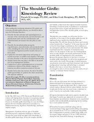
3. ANAESTHESIA MACHINE DESCRIBTION<br />
An anesthesia machine is a device which is used to deliver precisely known but<br />
variable gas mixture including anesthetic and lif- sustaining gases to the patient's<br />
respiratory system . Generally, a variable concentration gas mixture of oxygen, nitrous<br />
oxide and anesthetic vapor like ether or halothane is obtained from the machine and is<br />
made to flow through the breathing circuit to the patient . It is composed of two<br />
subsystems ( fig. 7 ).<br />
- the gas supply – delivery unit , which consists of tubing and<br />
flowmetres interconnected in parallel. And<br />
- The anesthetic vaporizer, which is used to produce an anaesthetic<br />
vapour from a volatile liquid.<br />
==============================( 5 )=============================
Anesthesia<br />
==============================================================<br />
FIG 7<br />
==============================( 6 )=============================
Anesthesia<br />
==============================================================<br />
3.1 GENERAL ANESTHESIA PRACTICE<br />
Usually, there are four phases in al techniques of general anesthesia: induction,<br />
maintenance, emergence and recovery. The patient will undergo a pre-operative<br />
preparation procedure before being commenced to these phases.<br />
During pre-operative preparation, the patient will be given a certain drug which is called<br />
"premedication. "<br />
The reasons for this pre-medication are:<br />
1. To raise the pain threshold.<br />
2. To reduce reflex central nervous activity (e.g. salivation, vagus nurve).<br />
3. To sedate.<br />
4. To counteract unwanted side effects caused by the anesthetic agent.<br />
5. Facilitation of the induction of anesthesia.<br />
6. Reduction of salivary and bronchial secretions.<br />
An adequate premedication is an essential factor in all forms of anesthesia. In a well<br />
premedicated patient, the dosage of anesthetic agent can be kept to a minimum and the<br />
disadvantages of otherwise large amounts of agent can be avoided. In balanced general<br />
anesthesia, the patient will be given an induction agent by intravenous short-acting<br />
barbiturate. The patient is thus put to sleep quickly and pleasantly. In some certain cases<br />
(pediatrics), the patient will be induced to anesthesia by inhaling a mixture of oxygen and<br />
nitrous oxide by face mask and slowly inducing the inhalational agent in small<br />
increments.<br />
After the patient is properly positioned on the operating table, the operation may<br />
commence. When the operation is concluded, the depth of anesthesia should be lightened<br />
and the patient should be allowed to emerge. The phase of maintenance refers to the<br />
period beginning with the onset of surgical anesthesia and ending with emergence. The<br />
anesthesia is maintained by administering a mixture of oxygen and nitrous oxide<br />
supplemented by a volatile inhalation agent, for example, halothane. Sometimes, a<br />
neuroleptic agent (a drug which provides mental detachment from patient surroundings)<br />
is given to the patient which, besides its sedative effect, also counteracts the nausea<br />
which can accompany large doses of analgesics. How soon the maintenance phase is<br />
reached varies greatly and depends, among other things, upon the patient's general<br />
conditions and the premedication drugs received.. The agent's solubility in various tissues<br />
are of importance as for example, it takes longer to anesthetise an obese patient because<br />
the anesthetic agent is highly soluble in fatty tissue (taking longer to become saturated)<br />
and for the same reason, recovery takes longer in the obese patient. The muscular<br />
relaxation is of importance at this phase in order to allow the surgeon to operate freely,<br />
but the patient's tubation, if required, should be carried out before giving muscle<br />
relaxants.<br />
Muscle relaxation in general anesthesia can be achieved by deeply anesthetising the<br />
patient (by increasing the agent concentration), but it is much more common nowadays to<br />
==============================( 7 )=============================
Anesthesia<br />
==============================================================<br />
give muscle relaxants and the risk of exessively deep anesthesia are then avoided. The<br />
muscle relaxants block the normal transmission between the nerve ending and the muscle.<br />
Because these muscle relaxants paralyze the respiratory muscles, the anesthetist must<br />
give artificial respiration to the patient with the aid of a ventilator. Also, because of the<br />
use of this muscle relaxant during general anesthesia, the patient is often intubated to<br />
provide a safe airway and maintain adequate ventilation, while for shorter operations and<br />
when muscle relaxants are not used, anesthetic gases are administered via a face mask.<br />
At the end of the surgical anesthesia and as soon as neuromuscular function returns and<br />
ventilation is adequate, the administration of nitrous oxide and volatile agent is<br />
discontinued and the patient is allowed to emerge from the stage of surgical anesthesia. If<br />
muscle relaxant has been given, it is important not to let the patient regain consciousness<br />
before neuromuscular function returns as the experience of being awake but paralyzed is<br />
extremely unpleasant. The patient will be allowed to breath pure oxygen at high flow for<br />
at least 2 minutes before he is allowed to breath room air. This is to flush out the large<br />
amount of nitrous oxide leaving pulmonary capillary blood during this phase into the<br />
alveolar and prevent diffusion hypoxia. The patient then is to be admitted to a post<br />
anesthesia recovery area for continuing observation and care.<br />
3.2Anesthesia Drugs:<br />
» Pre medication<br />
. 30-60 minutes before starting anesthesia<br />
. To remove fear and anxiety<br />
. Examples:<br />
. Benzodiazepines, Barbiturates and Opioids<br />
» Pre Induction drugs<br />
. Vagolytics are administered prior to induction to<br />
. Protect the heart from of anesthetic agents' depressant effects but may cause<br />
unwanted changes in heart rhythm<br />
. Reduce airway and gastric secretions and sweating<br />
. Includes:<br />
. Atropine<br />
. Glycopyrrolate<br />
» Induction<br />
. To put patient to sleep<br />
. Done using:<br />
. Inhalational anesthetics with Children or<br />
. intravenous anesthetics with adults (thiopental and Propofol)<br />
. Intravenous analgesics (for pain removal) and NMBAs begins simultaneously with<br />
anesthetics<br />
. Inhalational anesthetic agents are: Halothane, Enflurane, Isoflurane,<br />
Sevoflurane and Desflurane together with N2<br />
==============================( 8 )=============================
Anesthesia<br />
==============================================================<br />
4.Purpose of anesthesia units:<br />
Anesthesia units dispense a mixture of gases and vapors and vary the proportions to<br />
control a patient's level of consciousness and/or analgesia during surgical procedures.<br />
Basically, anesthesia units perform the following four functions:<br />
. Blend gas mixtures that can include (besides 02) an anesthetic vapor, nitrous oxide<br />
(N20), other medical gases, and air<br />
. Facilitate spontaneous, controlled, or assisted ventilation with these gas mixtures<br />
. Reduce, if not eliminate, anesthesia-related risks to the patient and clinical staff<br />
The patient is anesthetized by inspiring a mixture of 02, the vapor of a volatile liquid<br />
halogenated hydrocarbon anesthetic, and, if necessary, N20 and other gases. Because<br />
normal breathing is routinely depressed by anesthetic agents and by muscle relaxants<br />
==============================( 9 )=============================
Anesthesia<br />
==============================================================<br />
administered in conjunction with them, respiratory assistance - either with an automatic<br />
ventilator or by manual compression of the reservoir bag - is usually necessary to deliver<br />
the breathing gas to the patient.<br />
5.Principles of operation :<br />
An anesthesia system comprises four basic subsystems: a gas supply and control circuit, a<br />
breathing and ventilation circuit, a scavenging system, and a set of system function and<br />
breathing circuit monitors (e.g., inspired 02 concentration, breathing circuit integrity).<br />
Also included in some anesthesia systems are a number of monitors and alarms that<br />
indicate levels and variations of several physiologic variables and parameters associated<br />
with cardiopulmonary function and/or gas and agent concentrations in breathed-gas<br />
mixtures. Manufacturers typically offer a minimum combination of monitors, alarms, and<br />
other features that customers must purchase to meet standards and ensure patient safety.<br />
To meet the minimum standard of care in the United States, anesthesia machines must<br />
monitor 02 concentration, airway pressure, and either the volume of expired gas (V exp)<br />
or the concentration of expired CO2. Stand-alone monitors may be used to track other<br />
essential variables such as electrocardiogram, temperature, and blood pressure.<br />
5.1-Gas supply and Control :<br />
Because 02 and N20 are used in large quantities, they are usually drawn from the<br />
hospital's central gas supplies.<br />
valve, and a regulator that lowers the pressure to approximately 45 pounds per square<br />
inch (psi). There is no need for a separate regulator when the central gas supply is used<br />
because the pressure is already at about 50 psi.<br />
Most anesthesia machines have an 02 supply failure device and alarm that protect the<br />
patient from inadequate 02 supply. If the 02 supply pressure drops below about 25 to 30<br />
psi, the unit decreases or shuts off the flow of the other gases and activates an alarm.<br />
The flow of each gas in a continuous-flow unit is controlled by a valve and indicated by a<br />
flowmeter. The flowmeter can be a purely mechanical arrangement, with a flow tube in<br />
which a bobbin moves up and down depending on the flow, or it can be an electronic<br />
sensor with an LCD (liquid crystal display). After the gases pass through the control<br />
valve and flowmeter, enter the low-pressure system, and, if required, pass through a<br />
vaporizer, they are administered to the patient. On machines sold in the United States, the<br />
N20 and 02 flow controls are interlocked so that the proportion of 02 to N20 can never<br />
fall below a minimum value (nominal 0.25) to produce a hypoxic breathing mixture. An<br />
02 monitor that is located on the inspiratory side of the breathing circuit analyzes gas<br />
sampled from the Y-piece of the patient's breathing circuit and displays 02 concentration<br />
in volume percent. 02 monitors should sound an alarm if the 02 concentration falls below<br />
the preset limitIf the flow of anesthetic gases to the patient must be stopped for any<br />
reason, an 02 flush valve can be activated to provide a large flow of central-source 02 to<br />
==============================( 10 )=============================
Anesthesia<br />
==============================================================<br />
purge the breathing circuit of anesthetic vapors. The 02-flush flow bypasses the<br />
flowmeters and vaporizers.<br />
In some units, the anesthetic gas flow momentarily shuts off.<br />
5.2-Vaporizers :<br />
Because the inhaled anesthetic agents, with the exception ofN20, exist as liquids at room<br />
temperature and sea-level ambient pressure, they must be evaporated by a vaporizer.<br />
Vaporizers add a controlled amount of anesthetic vapor to the gas mixture. Some<br />
anesthesia units can accommodate up to three vaporizers. Most units have a lockout<br />
mechanism that prevents the use of more than one vaporizer at a time.<br />
There are several types of vaporizers, including variable bypass (conventional), heated<br />
blender, measured flow, and draw-over. Variable bypass vaporizers can be either<br />
mechanically or electronically controlled.<br />
Variable bypass and heated blender vaporizers are concentration calibrated and thus can<br />
deliver a preselected concentration of vapor under varying conditions.<br />
In a variable bypass vaporizer, such as one used for enflurane, isoflurane, halothane, or<br />
sevoflurane, a shunt valve divides the gas mixture entering the vaporizer into two<br />
streams; the larger stream passes directly to the outlet of the vaporizer, while the smaller<br />
==============================( 11 )=============================
Anesthesia<br />
==============================================================<br />
stream is diverted through an internal chamber in which vapor fills the space over the<br />
relatively volatile liquid anesthetic. The vapor mixes with the gas ofthe smaller stream,<br />
which then rejoins the larger stream as it exits the vaporizer. In a mechanically controlled<br />
variable bypass vaporizer, a bimetallic thermal sensor that regulates the shunt valve to<br />
divert more or less gas through the chamber compensates for temperature changes that<br />
affect the equilibrium vapor pressure above the liquid. Each variable bypass vaporizer is<br />
specifically designed and calibrated for a particular liquid anesthetic.<br />
The heated blender vaporizer was introduced for use with the anesthetic agent desflurane.<br />
In this type of vaporizer, desflurane is heated in a sump chamber. A stream of vapor<br />
under pressure flows out of the sump and blends with the background gas stream flowing<br />
through the vaporizer. Desflurane concentration is controlled by an adjustable, feedbackcontrolled<br />
metering valve in the vapor stream.<br />
Measured-flow vaporizers (also known as copper kettle or flowmeter-controlled) are not<br />
concentration.<br />
==============================( 12 )=============================
Anesthesia<br />
==============================================================<br />
A few anesthesia units now have a liquid-injector type of vaporizer. This vaporizer is<br />
electronically controlled and injects the liquid anesthetic agent directly into the stream of<br />
gases.<br />
5.3 Ventilation :<br />
Manual ventilation, which requires that an operator manually squeeze the reservoir bag<br />
for each patient breath, can be tiring during long procedures and can compete with other<br />
tasks; therefore, an automatic ventilator is often used to mechanically deliver breaths to<br />
the patient. These ventilators, which have a minimal number of control settings and are<br />
usually electronically controlled and pneumatically powered, use a bellows in place of the<br />
manually compressed reservoir bag. The ventilator forces the anesthesia gas mixture into<br />
the patient's breathing circuit and lungs and, in a circle breathing system, receive<br />
exhaled breath from the patient as well as fresh gas. The anesthetist can vary the volume<br />
of a single breath (tidal volume) and the ventilation rate, either directly by setting them<br />
on the ventilator or indirectly by adjusting parameters such as the duration of inspiration,<br />
the inspiratory flow, and the ratio of inspiratory to expiratory time. The ventilatory<br />
pattern is adjusted to the varying needs of the patient. For patients with special respiratory<br />
support needs, a more sophisticated ventilator with capabilities similar to those used in<br />
critical care applications may be required.<br />
Minute ventilation, the total volume inspired or expired during one minute, can be<br />
evaluated as the product of the expired tidal volume and the ventilation rate. It requires<br />
careful monitoring, not only because it is physiologically important to the patient, but<br />
also because it can indicate malfunctions of the ventilation delivery system (e.g., leaks in<br />
the breathing circuit).<br />
The expired tidal volume can be measured with a flowmeter, with a spirometer, or with a<br />
sensor placed in the expiratory circuit. Some anesthesia ventilators can also limit the peak<br />
inspiratory pressure, slow the rate of exhalation, provide ventilation only when the patient<br />
is not making inspiratory efforts, and maintain a positive airway pressure during the<br />
expiratory phase of the breath (positive end-expiratory pressure [PEEPD]).<br />
5.4-Breathing circuits<br />
Most anesthesia systems are continuous-flow systems, which provide a continuous supply<br />
of 02 and anesthetic gases. There are two basic types of breathing circuits used in these<br />
systems: the circle system and the T-piece system, each of which can assume various<br />
configurations. (A common configuration of the T-piece system is the Bain modification<br />
of the Mapleson D system.) A higher proportion of anesthetic gases is rebreathed in the<br />
circle system, which uses check valves to force gas to flow in a loop and returns expired<br />
gases (minus the CO2), plus fresh gas, to the patient. In the T -piece circuit, most of the<br />
==============================( 13 )=============================
Anesthesia<br />
==============================================================<br />
exhaled gas is vented out of the system, and the portion rebreathed depends on the freshgas<br />
flow rate.<br />
In the circle system, fresh gas from the anesthesia machine enters the inspiratory limb of<br />
the breathing circuit and mixes with gas in the system before the resulting mixture flows<br />
through a one-way valve to the patient. Expired gas flows from the patient through a<br />
second (expiratory) limb of the circuit, passing another one-way valve, into either a<br />
reservoir bag or a ventilator bellows. When positive pressure is generated in the system,<br />
either by a manual squeeze of the reservoir bag or by compression of the bellows by a<br />
mechanical ventilator, collected gas that does not escape via an adjustable pressurelimiting<br />
(APL) valve to the scavenging system is driven through a CO2 absorption<br />
Figure 2-4: continous flow anesthesia system<br />
canister or LIOH or Amsorb and back to the patient. The canister contains either soda<br />
lime or barium hydroxide lime that removes CO2 from the rebreathed gases. In circle<br />
breathing systems, a fresh-gas flow of 1 L/min or less is typically considered low-flow<br />
anesthesia (4 to 10 L/min is typically considered the usual fresh-gas flow rate). A freshgas<br />
flow of 0.5 L/min is generally considered minimal-flow anesthesia. In situations in<br />
which the cost of anesthetic agents is high, low-flow anesthesia may be the preferred<br />
option.<br />
Machines with a T-piece design have corrugated tubing in which fresh gas and some<br />
expired gas mix before entering the patient at each inhalation. Partial rebreathing is<br />
controlled by the supply rate of fresh gas, and the exhaled anesthetic mixture leaves the<br />
circuit through an APL valve. Elimination of rebreathed CO2 depends on fresh-gas flow<br />
==============================( 14 )=============================
Anesthesia<br />
==============================================================<br />
and occurs in direct proportion to that flow. This system, although adaptable to a variety<br />
of anesthetic procedures, is used most often in pediatric anesthesia.<br />
Circle systems offer advantages over T-piece systems in that they conserve a greater<br />
proportion of the anesthetic gases and conserve body heat and moisture from the patient.<br />
The advantages of T-piece systems include a lower circuit compliance, easier circuit<br />
sterilization, and a less complex design requiring fewer valves and no CO2 absorber<br />
(although one can be used with it).<br />
Because excess pressure imposed on the patient's lungs can cause serious lung damage,<br />
either an APL valve or a valve in the ventilator allows excess gas to escape when a preset<br />
pressure is exceeded. There are two types of APL valves: spring-loaded and needle<br />
valves. The spring tension in spring-loaded APL valves can be adjusted to control the<br />
pressure at which the valve will open. At lower pressures, the valve is closed.<br />
The pressure in the breathing system maintained by the needle valve depends on the flow<br />
through the valve.<br />
Therefore, when the valve is not fully closed, gas will always leak from the system. The<br />
minimum exhaust pressure required to refill a ventilator bellows is usually 1 to 2 cm<br />
H2O; for maximum pressure, both types of valve are fully closed. Because many APL<br />
valves do not have calibrated markings, the anesthetist must adjust them empirically to<br />
give a desired peak inspired pressure. Circle systems and T-piece systems also include a<br />
pressure gauge for monitoring circuit pressure and setting the APL valve. An<br />
electronically controlled, settable, and calibrated APL valve is available on some<br />
anesthesia machines.<br />
==============================( 15 )=============================
Anesthesia<br />
==============================================================<br />
Figure 2-5 breathing circuits<br />
5.5-Scavenging system :<br />
A scavenging system captures and exhausts waste gases to minimize the exposure of the<br />
operating room staff to harmful anesthetic agents. Scavenging systems remove gas by a<br />
vacuum, a passive exhaust system, or both. Vacuum scavengers use the suction from an<br />
operating room vacuum wall outlet or a dedicated vacuum system. To prevent positive or<br />
negative pressure in the vacuum system from affecting the pressure in the patient circuit,<br />
manifold-type vacuum scavengers use one or more positive or negative pressure-relief<br />
valves in an interface with the anesthesia system. In contrast, open-type vacuum<br />
scavengers have vacuum ports that are open to the atmosphere through some type of<br />
reservoir; such units do not require valves for pressure relief.<br />
Passive-exhaust scavengers can vent into a hospital ventilation system (if the system is<br />
the nonrecirculating type) or, preferably, into a dedicated exhaust system. The slight<br />
pressure of the waste-gas discharge from the anesthesia machine forces gas through<br />
largebore tubing and into the disposal system or directly into the atmosphere.<br />
==============================( 16 )=============================
Anesthesia<br />
==============================================================<br />
5.6 Monitors and alarms :<br />
Anesthesia systems incorporate a set of equipmentrelated monitors, including those for<br />
airway pressure, expiratory volume, and inspired 02 concentration.<br />
They can also include exhaled anesthetic agent monitors, such as those for CO2<br />
concentration, N20 concentration, and agent concentration, or physiologic monitors such<br />
as those for blood 02 saturation by pulse oximetry, electrocardiogram, invasive and<br />
noninvasive blood pressure, and temperature.<br />
Anesthesia systems are typically configured with respect to their monitors in one of two<br />
ways: as modular systems or as preconfigured systems. In the modular approach, an<br />
anesthesia machine with a basic set of equipment monitors (usually airway pressure,<br />
inspired 02 concentration, and expired volume) is used as a physical platform for the<br />
system. Additional physiologic monitors, individually or in a monitoring system (with its<br />
own display and alarms), along with other devices as needed, are obtained separately and<br />
added to the system. The preconfigured approach involves a more completely integrated,<br />
manufacturer-assembled system that already includes all physiologic and equipment<br />
monitors and displays in a turnkey unit.<br />
Some units may have methods of integrating, analyzing, displaying, and recording the<br />
information generated by the monitors' sensors and alarms.<br />
Microprocessors have been incorporated into the systems to implement these functions.<br />
Stand-alone microprocessor-controlled data collection and display units have been used<br />
to integrate modular anesthesia systems.<br />
These units can also be used as part of an anesthesia information management system<br />
(AIMS).<br />
Integration of the information and alarms from each of the monitors into a single display<br />
has become very important. An integrated display gives the anesthetist a single point of<br />
reference for a wide variety of equipment and physiologic information. Anesthesia<br />
machines that lack integrated alarms can sometimes cause confusion among anesthetists<br />
and operating room teams by sounding numerous alarms simultaneously. In an integrated<br />
system of information and alarms, visual alarm messages appear on a central display;<br />
furthermore, audible and visual alarms are prioritized so that the more urgent alarm<br />
sounds and visual signals are associated with the more vital monitored variables.<br />
An anesthesia workstation is designed to centralize system control and to integrate the<br />
display of information. This involves continuous acquisition, recording, and presentation<br />
on a central display of selected monitored physiologic and equipment variables (in real<br />
time or using historical trends) along with limit settings and the status of all alarms, plus<br />
explanatory messages.<br />
==============================( 17 )=============================
Anesthesia<br />
==============================================================<br />
Several models exist to predict the level of wakefulness in anesthetized patients, such as<br />
the Ramsay Scale and the Modified Observer's Assessment of Alertness/Sedation Scale.<br />
However, in lieu of a direct method of monitoring brain activity during surgery, users<br />
may rely on indirect means of assessing consciousness, such as blood pressure and vital<br />
signs.<br />
According to proponents, one indirect method, the Bispectral Index (BIS), or<br />
Physiometrix's Patient State Index, measures the effectiveness of painkilling agents while<br />
ignoring the sedative and paralytic elements that constitute a significant portion of<br />
anesthetic agents. Some anesthesia units may incorporate this technology as an additional<br />
tool to monitor the patient.<br />
BIS monitors use a metered scale (0 to 100) to indicate the degree of patient wakefulness<br />
based on collected and processed data. A digital meter indicates the number on the scale<br />
that corresponds to the patient's degree of wakefulness, with a higher number<br />
representing a higher degree of consciousness and awareness of sensation despite the<br />
presence of anesthetic agents.<br />
5.7 Monitoring Function<br />
• Delivery of hypoxic gas mixture to the patient . This can be detected using<br />
oxygen analyzer in the breathing circuit.<br />
• Inability to adequately ventilate the lungs by not producing positive pressure in<br />
the patient’s lung inadequate volume of gas or improper breathing circuit<br />
connections . This can be monitored by pressure in the breathing circuit , the<br />
volume exhaled from the patient’s lung , and the amount of exhaled carbon<br />
dioxide.<br />
• Delivery of an overdose for an inhalational anesthetic agent which could be<br />
detected by agent – specific gas analyzer.<br />
• Devices can monitor these events are : Pressure monitor, oxygen monitor ,<br />
volume monitor CO2 monitor , and spectrometers.<br />
Never monitor the anesthesia delivery system performance through the patient’s<br />
physiological response .<br />
Breathing Circuits :<br />
• It is used to avoid and a adequate volume of a controlled concentration of fresh<br />
gas to the patient during inspiration and to carry the exhaled gases away from the<br />
patient during exhalation .<br />
• Open circuit , no re breathing of any gases and to CO2 absorber or valves.<br />
• Closed circuit : indicating the presence of CO2 absorber an some re breathing of<br />
other gases.<br />
==============================( 18 )=============================
Anesthesia<br />
==============================================================<br />
6. Mechanical Ventilation<br />
• Volume ventilation; the volume of gas delivered to the patient remains constant<br />
regardless of pressure that is required .<br />
• It is the most popular , since volume delivered remains constant despite changes<br />
in lung compliance .<br />
• Pressure ventilation; the ventilator provides whatever volume to the patient that is<br />
required to produce some desired pressure in the breathing circuit.<br />
• It is useful when compliance losses in the breathing circuit are high relative to the<br />
volume delivered to the lung.<br />
• Humidification reduces heat loss and maintains the integrity of the cilia that line<br />
the airway and promote the removal of mucus and particulate matter from the<br />
lungs .<br />
• Humidification of dry breathing gases can be accomplished simple passive heat<br />
and moisture exchangers inserted into the breathing circuit at the level of the<br />
endotracheal tube connectors.<br />
• Humidification can also be accomplished by electronic humidifiers that heat a<br />
reservoir filled with water and also heat a wire in the gas delivery tube to prevent<br />
rain – out of the water before it reaches the patient<br />
• Electronic safety measures must be included in these active devices due to the<br />
potential for burning the patient and the fire hazard .<br />
7.Gas Scavenging Systems<br />
• It is used to reduce or eliminate the potential hazard to employees who work in<br />
the environment.<br />
• Usually , more gas is administered to the breathing circuit than is required by the<br />
patient , resulting in the need to remove excess gas from the circuit .<br />
• The system must be able to collect gas from all components of the breathing<br />
circuit valves, ventilators , gas monitors , etc. without affecting the pressure and<br />
gas flow to the patient.<br />
• Open interface a simple design that require a large physical space for the reservoir<br />
volume.<br />
==============================( 19 )=============================
Anesthesia<br />
==============================================================<br />
• Closed interface , with an expandable reservoir bag, which must include relief<br />
valves for handling the case of no scavenging flow and great excess of scavenging<br />
flow<br />
• Trace gas analysis must be performed.<br />
8. Gas Flow Through Two – Gas Anesthesia Machine<br />
Fig. 1 illustrates gas flow and mixing as well as functional components encountered<br />
in a typical two – gas anesthesia machine . On examining the gas flow through the<br />
machine one must realized that oxygen and nitrous oxide may be supplied from either<br />
the wall supply or from nitrous oxide may be supplied from either the wall supply or<br />
from cylinders through the hanger yoke assembly . Thereby providing the assurance of<br />
always having a full cylinder available . When suing the wall supply as the source of gas .<br />
one must be certain to remember to keep to all cylinders closed . it the cylinder pressure<br />
regulator is to reduce the pressure to something higher than the wall supply , then the<br />
check valve in the wall supply pipeline inlet will close . It this occurs the cylinders will<br />
be the only source of gas and they may become depleted without the user’s knowledge .<br />
9.Power outlet to ventilator<br />
This pathway provides a mean of supplying pneumatic power to a ventilator . There is<br />
a valve that remains closed unless the proper connector is attached thereby depressing the<br />
valve off its seat and allowing oxygen to flow into the pneumatics of the ventilator . One<br />
must be sure to understand that this oxygen never enters the ventilator bellows or patient<br />
circuit , it only provides a patient circuit , it only provides a pneumatic source to drive the<br />
ventilator. The oxygen flow required by the pneumatics of the ventilator may be<br />
considerable ; therefore , when using the cylinders as the oxygen source , the cylinders<br />
may become depleted sooner than expected.<br />
==============================( 20 )=============================
Anesthesia<br />
==============================================================<br />
FIG 1<br />
==============================( 21 )=============================
Anesthesia<br />
==============================================================<br />
10.Oxygen Supply Failure Alarm and the pressure Sensor Shutoff Valve<br />
These devices are both safety components designed to warn the used of a drop in<br />
oxygen pressure and to protect the patient from a hypoxic mixture of gases when oxygen<br />
pressure is lost . The oxygen supply failure alarm is a pressure sensitive device designed<br />
to produce a loud audible alarm whenever the oxygen pressure drops below 5% of<br />
normal . When the machine is in use and the oxygen pressure is lost , the alarm should<br />
sound for at least 7 seconds , thus providing time for the user to either turn on the backup<br />
cylinder or change to a full one . In Fig. 1 this device is located upstream of the second<br />
stage regulator and therefore alarms when the oxygen pressure reaches 20 to 30 psi .<br />
Once oxygen pressure has been elevated above the alarm setting , the nose should cease .<br />
The user must realize that this alarm is not activated when pressure of any gas other than<br />
oxygen is lost ; therefore the oxygen concentration in the fresh gas flow may change<br />
without warning to the anesthetist .<br />
The pressure sensor shutoff valve is also referred to by a variety of other name ; Fail<br />
Safe , Oxygen Failure Safety Valve , and Oxygen supply pressure . Failure Device (<br />
fig.2). This device , as the name implies , is sensitive to oxygen pressure within the<br />
anesthesia machine and is required by the ANSI machine standard . The function of this<br />
valve is to stop the flow of all gases other than oxygen whenever the oxygen supply<br />
pressure drops below 50% of normal . Usually the oxygen failure alarm is set slightly<br />
above the pressure sensor shutoff valve . thus the user is alerted before the drop in gas<br />
flow actually occurs . The user should understand that these safety devices are limited in<br />
their ability to protect the patient from a hypoxic mixture of gas , therefore , an oxygen<br />
analyzer should always be used in the patient circuit .<br />
The gas then travels through pressure reducing valves to the flow control knobs where<br />
flow is controlled through the flow meters . The gases mix with each other after<br />
ascending the flow meters and pass through the calibrated vaporizer \, where anesthetic<br />
agent is added to the mixture . The gas mixture then exits the machine via the machine<br />
outlet to enter the patient circuit<br />
==============================( 22 )=============================
Anesthesia<br />
==============================================================<br />
11.THE FUNCTION OF THE MAJOR COMPONENTS<br />
11.1Wall versus Cylinder Supply of Gases :<br />
Gas to the machine may be supplied from either the wall supply ( the built – in gas<br />
system within the hospital ) or the cylinders attached to the hanger yoke assembly .Wall<br />
supply pressure is typically 50 psi , a full cylinder of oxygen is 2.200 psi and nitrous<br />
oxide is 750 psi . Therefore , distal to the hanger, yoke assembly is a cylinder pressure<br />
regulator that reduces the pressure from the cylinder to that of the wall source ( 40 to 60<br />
psi ) . The double yoke assembly ( Fig .1 ) allows two cylinder of the same gas to be<br />
mounted to the anesthesia machine. Usually the cylinders are used only as a backup to the<br />
wall supply or if the machine is used when there is no piped - in gas . In this double<br />
yoke system the gauge will indicate the pressure in the fullest tank when both cylinders<br />
are turned on . Therefore , each tank must be tested separately to be certain that each is<br />
full . there is a check valve inside each yoke assembly which eliminates the possibility of<br />
the cylinder of higher pressure emptying into the lower one . There is also a check valve<br />
at the wall supply pipeline inlet which blocks gas flow from the machine into the wall<br />
supply pipeline inlet which blocks gas flow from the machine into the wall supply when<br />
cylinders are being used a a gas source . When a cylinder position is unoccupied a block<br />
supplied by the manufacturer should be in place to eliminate the possible leakage of gas .<br />
It is recommended that when using cylinders as the gas supply , only one cylinder be<br />
turned on at a time in a double – yoke assembly , thereby providing the The Oxygen<br />
Flush Valve<br />
When this valve is depressed , oxygen flows at a high rate ( 35 to 75 Ipm ) directly<br />
into the common gas line near the machine outlet ( fig.1) . it used to rapidly fill the<br />
patient circuit . This flush valve is most often used when the anesthetist is manually<br />
ventilating the patient, and the bag is not inflating as fast as needed ( usually due to<br />
leakage around the mask ) .<br />
==============================( 23 )=============================
Anesthesia<br />
==============================================================<br />
Fig 2<br />
==============================( 24 )=============================
Anesthesia<br />
==============================================================<br />
Since this valve shuts only 100% oxygen into the system, one must realize that if used<br />
excessively during an inhalation induction, the process may be delayed due to the dilution<br />
of anesthetic agent . If the valve malfunctions and remains in the open position , or the<br />
operator depresses it for an extended period of time , the possibility exists of over-<br />
inflating the patient's lungs.<br />
Second stage pressure Regulator<br />
This pressure regulator is used in the system to assure that a constant pressure of<br />
gas is delivered to the flow meters ( fig.1) if this valve were not in place , every time a<br />
fluctuation in delivery pressure occurred , the flow through the flow meters would<br />
change . This regulator steps down the pressure from 40 to 0 psi to -16 psi . In the case of<br />
nitrous oxide there may or may not be a second stage regulator present . If there is not ,<br />
then the pressure directed to the flow control valve at the flow meters is -∼50 psi<br />
Flowmeters<br />
The pressure of oxygen at this point is -∼16 psi and that of nitrous oxide is -∼50<br />
psi . Each individual glass flowmeter is ground and individually calibrated with its float .<br />
For this reason , floats and tubes are not interchangeable . The flowmeters are tapered in<br />
the grinding process and the diameter at the upper end is slightly larger than tat the lower<br />
end ( fig. 3) . With this design , the amount of gas flow around the float increases as the<br />
float is raised in the flowmeter . The flow control knob is attached to a needle valve .<br />
Turning the knob clockwise increase the flow and counterclockwise decrease it . The<br />
most recent anesthesia machines are designed to provide, whenever the machines are "<br />
ON" . a minimum oxygen flow of approximately 300 ml/min , even when the control<br />
knob is in the extreme counterclockwise position . The safety feature is designed to<br />
provide a flow of oxygen equal to the rate of minimum oxygen consumption the ANSI<br />
machine standard require that the oxygen flowmeter be on the extreme right of the bank<br />
of flowmeters . The flow control knobs are color coded for easy identification; for<br />
example , green for oxygen and blue for nitrous , oxide . In addition , the oxygen flow<br />
control knob has a unique " fluted . which is different from the others. This distinctly –<br />
==============================( 25 )=============================
Anesthesia<br />
==============================================================<br />
shaped knob is designed to help the anesthetist positively identify the oxygen control by<br />
touch .<br />
The accuracy of flowmeters has been examined by servral investigators . The<br />
result indicated that flowmeters mayb be inaccurate at settings between0 to 14 L/min.<br />
Therefore , an oxygen analyzer should always be used to avoid delivering a hypoxic<br />
mixture . The flow meters on Drager's Narkomed 2 A are certified to be accurate within<br />
+ 3% of full scale , at 20oc and 760 mm hg barometric pressure. Similarly standards of<br />
calibration are performed by all manufacturers . Nonetheless. inaccuracies have been<br />
found in some flowmeters and therefore , an oxygen analyzer should be used in order to<br />
avoid delivering a hypoxic mixture , particularly at low flows.<br />
Recent anesthesia machines features low and high range oxygen flowmeters<br />
which connect in series and are controlled by a single knob ( Fig. 4). The low flowmeter<br />
is calibrated from 100 to 1,000 ml/min, and the high flowmeter is calibrated from 1 to 12<br />
or 5 L/min . An old design of tandem flowmeters had separate knobs , for low and high<br />
flow control, but ,for obvious safety reasons , the one- knob design is more desirable.<br />
Newer machine designs also incorporated devices which alarm or will not allow hypoxic<br />
mixtures of oxygen and nitrous oxide .<br />
11.4 Vaporizer<br />
Calibrated vaporizer(s) are located downstream from the flowmeters ( fig.1).<br />
After the flowmeters, oxygen and nitrous oxide become thoroughly mixed as they flow<br />
through the common gas line approaching the vaporizer. The fresh gas enters the<br />
vaporizer through the fresh gas inlet, and soon thereafter a bypass mechanism directs a<br />
portion of the stream into the vaporizing chamber where it becomes saturated with<br />
anesthetic vapor ( fig.5) . The bypass mechanism is functional over a wide range of<br />
flows; typically newer vaporizers demonstrate linear output with flows ranging form 5 to<br />
15 liters . There also exists a temperature compensating device which functions to<br />
increase the flow into the vaporizing chamber at low temperatures and to decrease it at<br />
higher ones . The fresh – gas that was diverted around the vaporizing chamber mixes with<br />
the saturated gas in the mixing chamber and travels out through the fresh – gas outlet.<br />
Fig. Technological advances in agent – specific vaporizers have made them reliable ,<br />
accurate , and easy to use . Vaporizers on newer anesthesia machines are connected in<br />
series via a specially designed manifold known as and exclusion system . This makes it<br />
==============================( 26 )=============================
Anesthesia<br />
==============================================================<br />
possible to have only one vaporizer on at a time . However, there are many older<br />
machines in use today that do not have this exclusion system in place; therefore, the<br />
possibility exists of administering more than one volatile anesthetic to the patient.<br />
Fig.4<br />
==============================( 27 )=============================
Anesthesia<br />
==============================================================<br />
12.1 Factors Affecting Vaporizer Output<br />
The use of free– standing vaporizers brings into consideration several common<br />
problems . It is possible in some instances to reverse the fresh gas connections, thereby<br />
reversing the flow of gas through the vaporizer; an arrangement that has been reported to<br />
increase the output drastically . This free- standing arrangement also increase the possibly<br />
of tipping the vaporizer. When a vaporizers tipped beyond 54 o , the possibly exist of<br />
liquid agent spilling into areas other than the vaporizing chamber . With the volatile<br />
anesthetic agent in other areas of the vaporizer, the output may become unpredictably<br />
altered . Drager recommends that when their vaporizer is tipped beyond the allowable<br />
limits , it should be flushed out by running 10L/min of gas with the concentration dial on<br />
the highest setting for a period of up to 30minutes . The Cyprane Tec 4 vaporizer is<br />
designed with a baffling system that allows the vaporizer to be tipped 180o . It is<br />
recommended , however , that if a vaporizer has been tipped , it's output should be<br />
verified by an agent analyzer , or flushed out with high flows , before it is put back in use<br />
.<br />
Increased vaporizer output can occur with pressure fluctuation in the patient circuit .<br />
This phenomenon is referred to as the " pumping effect . " The pressure fluctuations are<br />
reflected back into the vaporizing chamber of the vaporizer and may cause a significant<br />
increase in the anesthetic concentration delivered . The effect , however, has been greatly<br />
diminished with the more recent deigns of vaporizers and machines. Newer designs<br />
incorporate unidirectional check valves and internal modifications in the vaporizer that<br />
eliminate the pressure fluctuations from reaching the vaporizing chamber.<br />
==============================( 28 )=============================
Anesthesia<br />
==============================================================<br />
Fig. 5<br />
==============================( 29 )=============================
Anesthesia<br />
==============================================================<br />
12.2 Vaporizer filling Mechanism<br />
To eliminate the possibility of filing a vaporizer with the wrong liquid agent, an agent<br />
– specific keyed filling developed (Figs . 6A.B) This device is color coded to match the<br />
corresponding anesthetic agent, and also has slots which align with the notches on the<br />
agent and also has slots which align with the notches on the collar of the agent bottle .<br />
This method of filling and emptying is slower than pouring directly from the bottle into<br />
the vaporizer filler port . These safety devices have lost their popularity with many<br />
anesthetists because, in addition to being slower, they may also have a tendency to leak .<br />
It is impotent to always place the vaporizer concentration kel in the “ off “ position<br />
before filling it or the liquid agent will spurt out when the filling port is opened .<br />
==============================( 30 )=============================
Anesthesia<br />
==============================================================<br />
Fig 6<br />
==============================( 31 )=============================
Anesthesia<br />
==============================================================<br />
12.2.1- Gas Supply System<br />
Gases are provided to the anaesthesia machine from either a pressurized hospital<br />
central supply or small storage cylinders attached to the machine .<br />
Centralized supply : Centralized supply systems consist of bulk or cylinder storage<br />
for main and reserve supply , control equipment including valves and pressure regulators,<br />
a distribution pipeline , and numerous supply outlets. The system is so designed and<br />
operated that the necessary supply of gases is always a available is always available .<br />
The gas supplied by the hospital is regulated and maintained at the wall outlet. Gases are<br />
supplied to the anaesthesia machine inlet from the central system via a flexible hose<br />
connected to the operating room wall outlet .In order to prevent interchanging the gas<br />
supply wall outlet with the incorrect anaesthesia machine inlet , for example , nitrous<br />
oxide for oxygen , non interchangeable connectors are used at each end of the hose . The<br />
two types of non interchangeable connections most commonly used are the diameter<br />
index Safety System ( DISS) and non – interchangeable quick couplers . Each type of<br />
connecton incorporates a male and female end that is specially designed for each type of<br />
gas. In addition to the connective design , colour – coded hoses for each specific gas are<br />
utilized .<br />
12.2.2- Gas Cylinders :<br />
A second gas supply source is the cylinders located in yokes attached to the<br />
anaesthesia machine . This supply can be utilized as either he main source when a central<br />
gas supply dies not exist , or a reserve when central gas supply is available .<br />
Yoke : Each anaesthesia machine has at least one yoke for an oxygen cylinder but<br />
most are provided with two . In addition to oxygen, most machine designs include a<br />
nitrous oxide yoke . In order to prevent incorrect placement of a tank into the wring yoke<br />
, two pins located in the yoke must fit into corresponding holes drilled into the tank neck<br />
. The placement of these pins and corresponding holes is unique for each gas . This<br />
identification system , which is referred to as the Tin Index Safety system , has been<br />
standardized to prevent the accidental fitting of a wrong cylinder to the yoke .<br />
==============================( 32 )=============================
Anesthesia<br />
==============================================================<br />
12.2.3- Pressure Gauge :<br />
Pressure gauge are attached to the cylinders to indicate the contents to the gases in the<br />
cylinders . For oxygen , the operating range of the gauge is 0 to 150 kg/cm 2 . Whenever<br />
the new oxygen cylinder is hooked up and taken in line , the indicator should be above<br />
this mark . With the gradual usage of the gas, the reading would drop gradually, when<br />
the indicator show that the pressure has fallen below the minimum level of acceptance ,<br />
the cylinder should be refilled . If for any reason , the pressure gauge shows a reading<br />
above 150kg/cm2 during use, the cylinder should be disconnected immediately and<br />
replaced.<br />
==============================( 33 )=============================
Anesthesia<br />
==============================================================<br />
12.2.4- Pressure Regulator :<br />
Machine pressure regulators reduce cylinder gas pressure to 275 kpa (40 psi ) before<br />
the gas flows through the machine . The regulators has one high – pressure inlet, one high<br />
– cylinder through anon – return valve . the no – return valve prevents the flow into an<br />
empty cylinder or back into the central piping system and also enables it's removal and<br />
replacement when the reserve cylinder is turned on without interrupting the supply of gas<br />
.<br />
12.2.5- Fail Safe System :<br />
From the supply , the gas flows into the inlet the inlet of the anaesthesia machine and<br />
is directed through the pressure safety system towards the flow delivery unit. The<br />
pressure safety system will not allow nitrous oxide to flow unless an oxygen supply<br />
pressure exists in the machine . The fail – safe system consists of a master pressure<br />
regulator valve located in the oxygen supply line. From the master regulator , a reference<br />
pressure is provided to the salve regulator valve controlling the pressure and flow of the<br />
nitrous oxide line . When sufficient oxygen pressure of 275 kpa is present in the master<br />
regulator , the reference pressure enables the slave regulator valve to open and for<br />
nitrous oxide to flow . Unfortunately, pure nitrous oxide can be delivered with only<br />
oxygen supply pressure present , oxygen flow is not required.<br />
Regulation now require oxygen – nitrous oxide ratio safeguards, which need a<br />
minimum continuous low flow of oxygen varying from 200 to 300 mL/min , as indicated<br />
by the low – flow Rota meter. In newly designed machines , ingenious mechanical<br />
devices prevent the delivery of gas mixtures with an oxygen concentration below a low<br />
limit. Oxygen – nitrous oxide ratios vary from 25 : 75 to 30 : 70 depending on the<br />
manufacturer .<br />
12.2.6- Gas Delivery Units :<br />
From the fail – safe system , the gas is directed to the flow delivery unit. Two<br />
methods have been used to accomplish delivery and control the gas mixture ; gas<br />
proportioning and gas mixing .<br />
In a gas proportioning system , the delivered concentration of each gas constituent is<br />
the function of a pre- determined . precisely controlled ratio of proportionality which is<br />
independent of the total gas flow . For example , for desired mixture of 70% nitrous oxide<br />
and 30% oxygen , the metered ratio mass delivery will always be 7.3 regardless of the<br />
==============================( 34 )=============================
Anesthesia<br />
==============================================================<br />
total flow rate . Concentration is only a function of the proportional relationship between<br />
constituents. It dose not rely on setting individual gas flows . An oxygen – nitrous oxide<br />
bleeder used in a manner similar to the oxygen air blenders commonly used with<br />
mechanical ventilator performs this function.<br />
Most current anaesthesia machines use gas mixing . In this technique , the flow rate of<br />
each constituent is independently controlled and measured by a delivery unit consisting<br />
of a needle valve and a rotameter. The needle valve functions as a flow controller and a<br />
means of turning the gas on and off. The rotameter is a variable orifice flowmeter and<br />
consists of a transparent tube with a tapered internal diameter and a floating bobbin flow<br />
indicator .<br />
During the administration of anaesthesia, it may be necessary to fill the patient<br />
breathing circuit with oxygen at a rate higher than what the gas delivery unit can supply .<br />
For example , such a situation exist any time the patient is disconnected to the breathing<br />
circuit . This higher flow of oxygen is supplied via the oxygen flush valve and line . The<br />
oxygen flush system provides a high flow ranging from 35 to 75 L/min at a high pressure<br />
, directly into the patient breathing circuit.<br />
Each has a specific delivery unit . These units are connected in parallel and exhaust<br />
into common manifold prior to leaving the machine . The final concentration and total<br />
flow determined by mixing the component flows are dependent functions and subject to<br />
the accuracy of the control and measurement equipment .<br />
12.2.7- Vapour Delivery :<br />
The various liquids that posses anaesthetic properties are too potent ( strong ) to be<br />
used as pure vapours . They are thus diluted in a carrier gas such as air and/or oxygen , or<br />
nitrous oxide and oxygen . The device that allows vapourization of the liquid anaesthetic<br />
agent and it’s subsequent admixture with a carrier gas for administration to a patient is<br />
called a vapourizer. Vaporizers thus producte an accurate gaseous concentration from a<br />
volatile liquid anaesthetic . The anaesthetic vapour can then be safely added to the<br />
previously metered oxygen and nitrous oxide as the mixture leaves the mixing manifold.<br />
Vapourizers are available in one of the two basic designs;the flowmetre controlled or<br />
the concentration – calibrated . In either device , the anaesthetic vapours are picked up<br />
from the vapourizer by a carrier gas consisting either of pure oxygen or an oxygen –<br />
==============================( 35 )=============================
Anesthesia<br />
==============================================================<br />
nitrous oxide mixture that bubbles through or passes over the liquid . The liquid surface<br />
areas to gas interface is designed to ensure the most efficient vapourization process . As<br />
aresult of vapourization a drop in liquid temperature is produced . As the liquid<br />
temperature decreases , a thermal gradient is established between the liquid and the<br />
surroundings. This results in a decrese in the quantity of the vapour produced . In order<br />
to maintain the performance of the vapourizer , the temperature drop is minimized or<br />
prevented by the incorporation of a thermal source . This is achived by using a water<br />
bath or surrounding the vaporizing liquid with a heating element . These devices may<br />
also control the temperature of the carrier gas entering the vapourizer . The materials<br />
selected for vapourizer construction require both a high specific heat and high thermal<br />
conductivity . Material with high specific heats will change temperature more slowly and<br />
maintain an appropriate thermal inertia. The higher the thermal conductivity , the higher<br />
the conduction of heat from the surroundings . Because of its availability and lower cost ,<br />
copper has been one of the most common materials used . Although not ideal, copper has<br />
a moderate specific heat and a high thermal conductivity. Early vapourizers were<br />
accordingly called “ copper kettle”.<br />
In order to proved a stable and predictable concentration of anaesthetic vapour , the<br />
vapourizer include a suitable method of obtaining calibrated dilution of vapour to avoid<br />
administration of too powerful volatile anaesthetic agents to the patient . This can be<br />
dome by several means and the vapourizers are accordingly classified into various<br />
categories discussed below .<br />
12.2.8-Variable Bypass Vapourizer :<br />
Here the carrier gas flow from the flowmeter is split into two streams in a known<br />
ratio one stream which is called “ chamber flow “ , flows cover the liquid agent while the<br />
final concentration can be controlled by varying the splitting ratio between the vapourizer<br />
gas and the bypass using an adjustable valve (fig. 8)<br />
==============================( 36 )=============================
Anesthesia<br />
==============================================================<br />
Fig. 8<br />
==============================( 37 )=============================
Anesthesia<br />
==============================================================<br />
The splitting ratio of the two flows depends on the ratio of resistances to their flow ,<br />
which is controlled by the concentration control dial and the automatic temperature<br />
compensation vavle.<br />
Usually , less than 20% of the gas becomes enriched – saturated with vapour and<br />
more than 80% is bypassed , to rejoin at the vapourizer outlet . The output of current<br />
varialble bypass vapourizers is relatively constant over the range of fresh gas flows from<br />
approximately 250 mL/min to 15L/min. The output of vaporizers in linear at the ambient<br />
temperature ( 2o – 35 o C) due to automatic temperature compensating devices that<br />
increase carrier gas flow as the liquid volatile agent temperature decrease . Also, they are<br />
composed of metals with high specific heat and thermal conductivity . Check valves are<br />
provided to prevent back pressure effect on the vapourizer from the breathing circuit due<br />
to positive pressure ventilation.<br />
Measured – flow Vapourizers : In these devices , the anaesthetic agent is healed to a<br />
temperature above the boiling point and is then metred into the fresh gas flow . (fig. 9)<br />
Various anaesthetic gent have widely different potencies and physical properties and<br />
hence require vapourizers constructed specifically for each agent . They are thus agent –<br />
specific . They are only calibrated for a singl gas , usually with keyed filters that decrease<br />
the likelihood of filing the vaporizer with the wrong agent.<br />
:<br />
Vapourizer are provided with various safety related inter – locks which ensure tha<br />
- Only one vapourizer is turned on;<br />
- Gas enters only the on which is on<br />
- Trace vapour output is minimized when the vapourizer is off .<br />
- Vapourizers are locked into the gas circuit, thus ensuring that they are sealed<br />
correctly ; and<br />
- Other important safety features are followed including keyed filters and<br />
secured mounting to minimize tipping ( tilting ) which may obstruct the<br />
working of the valves.<br />
12.2.9- Delivery System :<br />
Patient Breathing System : the function of a patient breathing system is to deliver<br />
anaesthetic and respiratory gases to and from the patient . It describe both the mode of<br />
==============================( 38 )=============================
Anesthesia<br />
==============================================================<br />
operation and the apparatus by which inhalation agents are delivered to the patient. The<br />
breathing system may be :<br />
. Re -breathing Type: This refers to re – breathing of some or all of<br />
the previously exhaled gases , including carbon dioxide and water<br />
vapour .<br />
. Non- re- breathing Type : In this a fresh gas supply is delivered to<br />
the patient and re – breathing of previously exhaled gases is<br />
prevented . Usually , non – rebreathing type systems are applied in<br />
practice . This is achieved by using : - Uni – directional ( circle )<br />
system , and<br />
• Bi – directional ( to – and – fro ) system .<br />
Fig. 10<br />
==============================( 39 )=============================
Anesthesia<br />
==============================================================<br />
Fig. 10 shows the principle of a non – re -breathing system which uses uni –<br />
directional non – breathing valve . Fresh gas entering the inspiratory part is either sucked<br />
in by the patient's inspiratory effort or blown in during controlled that when it is open to<br />
admit inspiratory gas, it does not permit the flow from the expiratory part to get through it<br />
. When the patient exhales , the reverse happens , as the inspiratory valve is occluded and<br />
the expiratory valve is opened to allow expiratory gases to escape . The inspiratory<br />
system usually includes a rubber bag of two – liter capacity which acts as a reservoir for<br />
fresh gas . The reservoir bag is refilled with fresh gas during the expiratory phase . It can<br />
also be compressed normally to provide assisted or controlled ventilation . The fresh gas<br />
supply is linked to a length of corrugated breathing hose ( minimum length – 10 cm with<br />
an internal volume of 550 ml). This represents slightly morethan the average tidal volume<br />
in an aneaesthetized adult breathing spontaneously . this is , in turn , connected to a<br />
variable tension, spring – loaded flap value for venting off exhaled gases . This valve is<br />
located as close to the patient as possible as possible , and is called an APl ( adjustable<br />
pressure limiting ) valve . The APL valve works as pop – off valve to ensure that the<br />
patient is not subjected to the surges in the gas supply . When the pas encounters<br />
resistance from the patient , the excess gas pops out . The arrangement is shown in fig 11<br />
. In this case , carbon dioxide elimination is achieved by the flushing action of the fresh<br />
gas introduced with the breathing system , rather than by separation . Obviously , this<br />
systemretains the potential for re – breathing of carbon dioxide when the fresh gas flow<br />
rates are reduced .<br />
Fig. 11<br />
==============================( 40 )=============================
Anesthesia<br />
==============================================================<br />
Circle System : The circle is the most popular breathing circuit and is a closed loop of<br />
large – bore , low – pressure tubing divided into an inspiratory and an expiratory lim.<br />
Contained within this loop are two uni – directional valves , as CO2 absorber , circuit gas<br />
venting ( scavenging ) , an adjustable pressure – limiting valve, reservoir bag, and airway<br />
management equipment including masks and endotracheal tubes . The patient is<br />
connected to absorber by two corrugated hoses , one inspiratory and the other expiratory .<br />
Fresh gas is introduced proximal to a uni-directional inspiratory valve . During<br />
inspiration , gas move through the absorber from either the reservoir bag or ventilator<br />
bellows and inspiratory valve into the inspiratory lim of the circuit . The pressure<br />
difference between the inspiratory and expiratory limbs keeps the uni – directional<br />
expiratory valve closed . During exhalation , the pressure differential reverses . The<br />
inspiratory valve closes and the expiratory valve opens, allowing the exhaled gas to flow<br />
into the reservoir bag or ventilator bellows and bsorber . The APL or the pop – off valve<br />
enables the anaesthetist to control the circuit volume and pressure by the regulation of gas<br />
venting from the circuit . Circuit exhaust is either carried into the room or collected by a<br />
gas scavenging system .<br />
Uni- directional breathing valves are available in several design . This disk valve is<br />
the most common in modern systems . This valve consists of only one movable part , a<br />
flat disk. The disk is made of either plastic or metal and is held against the valve seat by<br />
either gravity or a mechanical spring. The valves are placed in transparent devices so that<br />
their action may be observed.<br />
The APL is designed to regulate circuit pressures by manually adjusting the spring<br />
tension against a disk. When circuit pressure overcomes the valve resistance, the disk is<br />
lifted from its seat and gas is allowed to exhaust from the circuit. The circuit volume and<br />
pressures throughout the delivery of anaesthesia are continuously observed so that the<br />
APL the APL valve can be appropriately adjusted.<br />
The absorber contains a carbon dioxide absorbent ( soda lime)in a closed container.<br />
Soda lime is used in the form of granules so that they have volume and large surface area<br />
.thus, the expiated air remains in contact with the coda lime for a relatively long period of<br />
timely, increasing the efficiency of absorption. Granules of an optimum size are selected<br />
as, too large a size leads to poor contact and poor absorption, while too small a size clogs<br />
the soda lime bed and causes resistance to the gas flow. The exhaled gas is made to flow<br />
thorough the absorber where the CO2 is removed. The remaining gas mixed with fresh<br />
==============================( 41 )=============================
Anesthesia<br />
==============================================================<br />
gas flowing from the machine and re- breathed via the inspiratory limb. When the soda<br />
lime gats consumed its color changes from pink to yellowish.<br />
The reservoir or breathing bag is highly complainant with an easily expanded volume.<br />
The bag allows the accumulation of gas during exhalation so that a reservoir is available<br />
for the next inspiration. It provides a means for visually monitoring the spontaneous<br />
breathing pattern of the patient and buffers increases in breading circuit pressure. The bag<br />
also provides a means that can be used to manually ventilate the patient. Either passive or<br />
active scavenging systems are utilized in removing the circuit exhaust. In passive<br />
scavenging, anaesthetic waste gases are vented directly into the existing room ventilation<br />
systems. The tubing, connects either the ventilator or the APL valve exhaust port of the<br />
breathing circuit to the hospital ventilation system. In active methods, the anesthetic<br />
circuit connects directly to a high flow vacuum system via appropriate interface.<br />
12.2.10- Humidification<br />
Dry gases supplied by the anaesthesia machine may cause clinically significant<br />
desiccation of mucus. This may contribute to retention of secretion and the mucus flow<br />
may cease. Lung compliance will consequently fall. Therefore, air or anaesthetic gases<br />
need to be humidified.<br />
Absolute humidity: this is the maximum mass of water vapour which can be carried<br />
by given volume of air (mg/L). this quantity is predominantly determined by temperature.<br />
Warm sir can carry much more moisture.<br />
Relative Humidity ( RH ) : This is the percentage of the amount of humidity present<br />
in a sample; as compared to the absolute humidity possible at the sample temperature . It<br />
is ideal to provide gases at body temperature and 100%, RH to the patient ‘ airway > the<br />
humidification measures that are commonly employed include heated airway humidifiers<br />
, nebulizers and heat and moisture exchangers.<br />
§ In the heated humidifiers , the air passes over the surface of the<br />
heted water and vapourization takes place . the temperature of the<br />
water is thermostatically controlled preferably , tow thermostats in<br />
series are used , so that if one thermostat fails , the other would<br />
still cut off the electric supply before dangerous temperature is<br />
reached . The temperature sensor is usually placed near the patient<br />
–end of the delivery tube so as ensure the maximum deficiency .<br />
§ Nebulizers aure used to supply moisture in the form of deroplets .<br />
A jet of air or gases may be used to entrain water drawn from a<br />
==============================( 42 )=============================
Anesthesia<br />
==============================================================<br />
reservoir fig. 12.. as the water enters the jet, it is broken up into a<br />
large number of droplets . Nebulizers based on this principle are<br />
also used in some ventilators . In ultrasonic nebulizers, water is<br />
broken into droplets by continuous bombardment of ultrasound<br />
energy which vigorously vibrates the water .<br />
§ Heat and moisture exchangers are based on the principle of<br />
conserving the patient’s own heat and moisture without external<br />
energy or water supply .<br />
Fig 12<br />
==============================( 43 )=============================
Anesthesia<br />
==============================================================<br />
§ The fibre – packed cartridges contain a moisture – absorbent<br />
material that absorbs the patient’s exhaled water and heat. During<br />
inspiration dry, inspired circuit gas flows through the warm,<br />
moisturized absorbent where it is warmed and humidified . Fibre<br />
cartridge are not as efficient at warning as humidfiers . However,<br />
they do significantly retard patient heat loss.<br />
For protection of patients from infection , clean or sterile disposable breathing<br />
circuits and bacterial filters have been advocated and widely used to reduce post –<br />
operative respiratory infections<br />
Although simple in design, breathing circuits can be source of may problems. The<br />
most common and serous problem is the potential for disconnection at any of several<br />
locations. Numerous investigators have shown that 10 – 15% of preventable mishaps<br />
result directly from airway leaks and disconnects . The cause for leaks and disconnects<br />
include poor fit due to incorrect size , incorrect shape taper connections , inappropriate<br />
fabrication of materials, thermal expansion , broken fittings and the absence of a locking<br />
device .<br />
12.2.11- Ventilators :<br />
An integral component of the anaesthetic delivery system is the ventilator . The<br />
ventilator provides a positive force for transporting respiratory and anaesthetic gases into<br />
an apneic patient . The ventilators prove positive pressure ventilation at a controlled<br />
minute volume ( Tidal volume, Rate ) They operate either electronically or mechanically<br />
with pneumatic or electric power source.<br />
Most of the currently used ventilators consist of a bellows contained within another<br />
housing . The bellows communicate directly with the breathing circuit and causes a pre-<br />
selected volume of gas to flow into the patient . The flow of gas into circuit results from<br />
collapsing the ventilator bellows by pressurizing the surrounding gas volume contained<br />
within the bellows housing.<br />
The ventilator is either located within the mainframe of the anaesthesia machine or is<br />
attached as an accessory unit .The outlet of the ventilator connects directly to the patient<br />
breathing circuit of the anaesthetic delivery system at the location and in place of the<br />
breathing reservoir bag. The ventilator thus functions as controller for both ventilation<br />
and circuit gas supply by replacing the functions of the reservoir bag and APL valve .<br />
==============================( 44 )=============================
Anesthesia<br />
==============================================================<br />
12.2.12- Patient Circuit :<br />
The patient circuit consists of black corrugated anti – static rubber tube , a chrome<br />
plated tube fitting ( T joint ) , a tow litre re- breathing bag, a Heidrink valve and a face<br />
mask with an elbow fitting. The face mask is designed to fit the patient’s face perfectly<br />
without any leaks and yet to exert the minimum of pressure which might depress the<br />
jaws and cause respiratory obstruction.<br />
12.2.13- Electronics In the Anaesthetic Machine<br />
Any delivery system is expected to meet accurately and safely , the patient’s varying<br />
requirements for respiratory and anaesthetic gases. The system must be able to monitor<br />
the function of the delivery system itself and the effect of the anaesthesai on the<br />
patient.Also, during the entire procedure the machine performance should not only be<br />
monitored and controlled , but it’s status should be continually assessed and recorded. In<br />
order to meet these requirement , the impact of electronics on the design and functioning<br />
of the anaesthetic machine has been phenomenal.<br />
The totally pneumatic anaesthetic machine stillhas many merits, which include it’s<br />
being easy to understand and easy to maintain, as also its cheaper cost and reliability .<br />
However , certain problems are encountered which directly affect the performance and<br />
safety of a pneumatic anaesthetic machine . This is overcome through the utilization of<br />
newer <strong>technologies</strong> and automation of instrumentation and anaesthetic delivery .<br />
Microprocessor – based anaesthetic equipment facilitates improvements in :<br />
§ Gas supply and proportioning systems;<br />
§ Breathing circuits;<br />
§ Gas scavenging and humidification devices ; and<br />
§ Ventilators .<br />
The use of microprocessor technology allows us to fully integrate control and safety<br />
functions and protects the patient from gas supply failure, electrical supply failure,<br />
hypoxic mixtures disconnections, vapourizer function , excessive airway pressure exhaled<br />
minute volume outside pre – set limits , oxygen or volatile agents outside the pre- set<br />
limit , end – tidal CO2 outside present limits and technical failure. All abnormal<br />
conditions cause an alarm to appear on the monitor panel , which also displays the nature<br />
of the fault.<br />
==============================( 45 )=============================
Anesthesia<br />
==============================================================<br />
Computer application with appropriate data processing inputs and outputs,<br />
automation and integration of machine functions and record – keeping are increasingly<br />
becoming possible . Ergonomically designed machines with easy to read and interpret<br />
display systems are also being commonly used.<br />
Anaesthesia has a profound effect upon all physiological systems . Most of these<br />
effects are deleterious, and therefore , it is important to know how the human body is<br />
affected by a anaesthesia . With a view to increasing patient safety and achieving a good<br />
degree of risk management , all systems affected by anaesthetic drugs must be monitored<br />
. This is done by using monitoring equipment with visible and audible alarms .<br />
Fig. 13<br />
==============================( 46 )=============================
Anesthesia<br />
==============================================================<br />
Since individual responses to a particular dose of a anaesthetic vary considerably , it<br />
advisable to measured the effect of the anaesthetic on a patient’s level of consciousness .<br />
One method to do so is to measure . Auditory Evoked Potentials ( AEP ) , which is a<br />
neuro – physiological indicator of the changes in the level of consciousness during<br />
anaesthesia . This is an electrical signal contained within the EEG which is obtained by<br />
delivering an auditory stimulus to the patient’s acoustic nerve . The fast extraction of the<br />
complex AEP signal , the brain’s response to the auditory stimulus of the acoustic nerve<br />
is obtained by mapping the signal and establishing an index which is developed as a<br />
graphic curve and a single number on the monitor screen fig 13 .This index which is<br />
calculated from a proprietary mathematical modeling method , quantifies the level of<br />
anaesthesia. For example , typically , if this index is higher than 60, the patient is awake ,<br />
and decreases in line with decreasing level of consciousness ( loss conscious typically<br />
occurring below 30) . Re - usable head – phones apply stimulation to the acoustic nerve<br />
to obtain AEP, which is then measured by a set of three disposable electrodes, two<br />
electrodes are applied in the forhead and one behind the ear to estimate the level of<br />
consciousness in a fast and non – invasive manner .<br />
13.Maintenance and Calibration<br />
Vaporizers should b drained of the liquid agent periodically to rid it of any<br />
contaminants that may be present . This drained liquid should be properly labeled and<br />
discarded . Halothane contain 0.01 percent thymol which is used to improve the stability<br />
of halothane . Thymol tends to accumulate in the vaporizer with time because it’s vapor<br />
pressure is much lower than that of halothane . High concentration of thymol may effect<br />
some of the internal components of the vaporizer thereby altering its accuracy . The<br />
increased thymol concentration may be noticed because it gives a brown tint to the liquid<br />
in the vaporizer .<br />
==============================( 47 )=============================
Anesthesia<br />
==============================================================<br />
13.1Anaesthetic apparatus: (Narkomed machines)<br />
13.1.1The pneumatic piping system:<br />
13.1.2Oxygen gas circuit<br />
Because oxygen is the primary gas for all Narkomed machines, we will begin our<br />
exploration of the pneumatic circuitry by tracing the flow of gas through the oxygen<br />
circuit The internal pneumatic circuit plays an important role in patient safety.<br />
Figure 14: The pneumatic circuit for a Narkomed two gas anesthesia system. The oxygen<br />
circuit is on the right.<br />
==============================( 48 )=============================
Anesthesia<br />
==============================================================<br />
13.1.3Cylinder Gas Supply Enters The Anesthesia System<br />
Oxygen from the E cylinder enters the anesthesia system through the yoke assembly,<br />
passing through the yoke check valve (Figure 15). The yoke check valve is a one-way<br />
valve that allows gas to enter the anesthesia system from the yoke, but does not allow gas<br />
to exit the anesthesia system through the yoke. As gas enters the yoke check valve, it<br />
forces the ball in the valve away seat. The seat. The gas flows around the ball and exits<br />
the yoke check valve through two holes in the side of the copper tubing connector. If the<br />
E cylinder is absent or empty, the gas supplied by the hospital piping system flows in the<br />
opposite direction (Figure 16). This gas flow forces the ball against the O-ring seat,<br />
sealing the entry port of the yoke assembly and retaining the hospital pipeline gas within<br />
the anesthesia system.<br />
Figure 15:<br />
Yoke check valve assembly - gas is flowing from the E cylinder through the yoke.<br />
Figure 16:<br />
Yoke check valve assembly - gas is flowing from the hospital pipeline gas supply toward<br />
the yoke.<br />
Pressure Reducing regulator<br />
1 Gas enters the anesthesia system from an E cylinder, through the yoke at a high<br />
pressure (typically ranging from 750 psi to 2200 psi). This pressure must be reduced for<br />
==============================( 49 )=============================
Anesthesia<br />
==============================================================<br />
the gas circuits of the anesthesia system. The pressure reducing regulator accomplishes<br />
this task in two phases. Figure (17) identifies the components of the regulator.<br />
Figure 17: pressure reducing regulator.<br />
13.1.5Phase 1<br />
High pressure gas flows from the yoke check valve to the inlet port of the regulator and<br />
enters the high pressure chamber (Figure 18). High pressure gas then flows from the high<br />
pressure outlet port to the cylinder pressure gauge. High pressure gas will remain trapped<br />
in the high pressure chamber until some adjustment is made to the main spring.<br />
Figure 18: high pressure gas enters to the regulator.<br />
Once the pressure control is set, it compresses the main spring that in turn moves the<br />
diaphragm. The diaphragm forces the nozzle away from the seat, allowing high pressure<br />
gas to flow into the low pressure chamber.<br />
==============================( 50 )=============================
Anesthesia<br />
==============================================================<br />
13.1.6Phase 2<br />
As the high pressure gas flows into the low pressure chamber, the diaphragm is forced<br />
backwards and the main spring is compressed (Figure 19). This allows the small spring<br />
behind the nozzle to move it toward the seat. When the gas pressure in the low pressure<br />
chamber equals the tension of the main spring, the nozzle closes against the seat, cutting<br />
off the flow of high pressure gas into the low pressure chamber. The gas in the low<br />
pressure chamber then flows through the low pressure port and into the pneumatic circuit<br />
of the anesthesia system. As the gas leaves the low pressure chamber and the pressure<br />
lessens, the main spring forces the diaphragm and the nozzle away from the seat, starting<br />
the whole cycle again.<br />
Figure 3-19: Gas pressure and spring pressure equalize.<br />
13.1.7-Cylinder Contents Pressure Gauge<br />
The high pressure gas that flows from the high pressure outlet port of the regulator is<br />
piped to a Bourdon pressure gauge. The pressure reading obtained from the gauge reflects<br />
the amount of gas remaining in the E cylinder. These gauges are used to measure gas<br />
pressure in large units, such as psi. This type of gauge is also used to measure pipeline<br />
gas pressure.<br />
The gauge consists of a hollow, curved tube connected to a gear rack that meshes with a<br />
pinion gear. A needle is mounted on the pinion gear shaft. When the gas pressure<br />
==============================( 51 )=============================
Anesthesia<br />
==============================================================<br />
increases inside the tube, the tube begins to straighten. This causes the gear train to move,<br />
which in turn rotates the needle around the face of the gauge.<br />
13.1.8-Pipeline Gas Supply Enters the Anesthesia System<br />
Gas supplied by the hospital piping system enters through a hose connected to the<br />
anesthesia system by a Diameter Index Safety System (DISS) fitting. The nut and stem<br />
assembly on the end of the hose mates to a matching DISS inlet on the anesthesia system.<br />
The stem and the body mate via the two shoulders on the stem that match two bores in<br />
the inlet Thus, mismatches between the shoulders and the bores will not allow the wrong<br />
gas to be connected to a given gas inlet. The DISS connectors are designed for the<br />
delivery of gases at less than 200 psi of pressure.<br />
Pipeline Check Valve<br />
Gas that enters through the DISS inlet flows to the pipeline check valve. The pipeline<br />
check valve performs the same function as the yoke check valve. It allows gas nom the<br />
hospital piping system to enter, but not exit, the anesthesia system. The pipeline check<br />
valve is mounted vertically with the pipeline gas entering from the bottom. As the gas<br />
flows upward, it lifts the piston and seal off the seat, and exits the pipeline check valve at<br />
the top (Figure 19). If the hospital pipeline gas supply fails, the piston and seal assembly<br />
drops onto the seat and prevents any gas supplied by the E cylinder nom escaping through<br />
the DISS inlet (Figure 20).<br />
==============================( 52 )=============================
Anesthesia<br />
==============================================================<br />
Figure 19: pipeline check valve forward flow.<br />
Figure 20: pipeline check valve reverse flow.<br />
Auxiliary Oxygen Flowmeter<br />
A tee fitting in the oxygen circuit supplies gas from either the pipeline or cylinder supply<br />
to the auxiliary oxygen flowmeter. This device can be activated whether the main switch<br />
is in the ON or STANDBY position. It allows the operator to deliver up to 10 Ipm of<br />
100010 oxygen to a patient, usually through a nasal cannula. This device is a convenience<br />
feature and is seldom used in the administration of general inhalation anesthesia.<br />
Oxygen Flush Button<br />
Regardless of whether the gas in the oxygen circuit was supplied by the hospital piping<br />
system or an E cylinder, a tee fitting allows oxygen to flow to the oxygen flush button at<br />
all times. The flush button consists of a valve and a restrictor. The flow restrictor is<br />
located in the outlet port of the valve.<br />
When the oxygen flush button is activated, it supplies the patient breathing circuit with<br />
100% oxygen. The flush button can be activated whether the main switch is in the ON or<br />
STANDBY position.<br />
When activated, the valve opens, permitting 50 psi of oxygen to be applied to the flow<br />
restrictor resulting in an output flow of approximately 55 l/min. This flow of oxygen is<br />
delivered to the patient breathing circuit through the fresh gas outlet.<br />
Locking Fresh Gas Outlet<br />
All gases flow from the coarse flowtube and enter the fresh gas circuit The fresh gas then<br />
flows through the vaporizer bank where anesthetic agent from a single vaporizer is added<br />
==============================( 53 )=============================
Anesthesia<br />
==============================================================<br />
to the fresh gas mixture. The fresh gas mixture then flows to the patient breathing circuit<br />
through the Locking Fresh Gas Outlet.<br />
The fresh gas outlet has a spring-loaded locking cap designed to prevent an accidental<br />
disconnect between the fresh gas outlet and the fresh gas hose of the patient breathing<br />
circuit The fresh gas outlet mates with the fresh gas hose through a standard 15 mm<br />
tapered fitting.<br />
System Power Switch<br />
A tee fitting allows both sources of oxygen to flow to the system power switch (Figure 3-<br />
10). With the system power switch in the STANDBY position, the valve remains closed<br />
eliminating pneumatic power.<br />
The leaf also switch remains closed eliminating electrical power.<br />
Figure 21: system power switch in the STANDBY position.<br />
As the system power switch is rotated to the ON position (Figure 22), the switch moves<br />
into the assembly. It depresses the valve plunger, allowing oxygen to flow to the rest of<br />
the oxygen circuit At the same time, the rotation causes the pin to move away from the<br />
leaf switch. The switch opens and activates the electrical circuitry of the anesthesia<br />
system. Notice that the leaf switch opens when turned ON, allowing the anesthesia<br />
system to remain in use should the leaf switch malfunction.<br />
==============================( 54 )=============================
Anesthesia<br />
==============================================================<br />
Figure 22: system power switch is on.<br />
Oxygen Supply Pressure Alarm Switch<br />
A tee fitting located directly downstream of the system power switch allows oxygen to<br />
flow to the oxygen supply pressure alarm switch. This pressure switch warns the operator<br />
of diminishing oxygen supplies. In the inactive position, oxygen pressure enters the<br />
bellows. The bellows expand in proportion to the gas pressure in the oxygen circuit<br />
(Figure 23). The bellows in turn compresses a spring and moves the connecting rod<br />
toward the electrical switch, opening the contacts. The switch remains open and the<br />
alarms are inactive as long as the pressure in the oxygen circuit remains above the set<br />
point.<br />
Figure 23: alarm inactivated.<br />
==============================( 55 )=============================
Anesthesia<br />
==============================================================<br />
As the gas pressure in the oxygen circuit decreases, the pressure inside the bellows also<br />
drops. As the pressure in the bellows drops, the spring causes the bellows to collapse,<br />
allowing the connecting rod to move away from the electrical switch (Figure 24). When<br />
the pressure falls below the set point, the electrical switch closes and the clinician gets<br />
both an audible and a visual alarm.<br />
Figure 24: alarm active.<br />
Flow Control Valve<br />
The oxygen circuit on a Narkomed anesthesia system terminates at the flow control<br />
valve. This valve regulates the flow of oxygen supplied to the patient breathing circuit<br />
through the fresh gas outlet. The valve consists of a threaded shaft with a tapered end that<br />
mates with a tapered seat. When the flow control valve is closed (Figure 25), the tapered<br />
end seals against the tapered seat and does not allow any gas to flow through the valve.<br />
==============================( 56 )=============================
Anesthesia<br />
==============================================================<br />
Figure 25: flow control closed position<br />
As the flow control valve is opened (Figure 26), the tapered end of the threaded shaft<br />
moves away from the seat, allowing the oxygen to flow through the valve. The greater the<br />
space between the tapered end and the tapered seat, the higher the gas flow.<br />
Figure 26: flow control open position<br />
Flowtubes<br />
After establishing gas flow through the flow control valve, the gas flow must be<br />
measured. All Narkomed anesthesia systems use two flowtubes, a fine flow tube that<br />
measures gas in ml/minutes and a coarse flowtube that measures gas in l/minutes. The<br />
fine and coarse flowtubes are connected in tandem to measure the flow of a given gas.<br />
Using tandem flowtubes allows for more accurate delivery of gas throughout the entire<br />
flow range. All flowtubes used in Narkomed anesthesia systems are permanently<br />
calibrated.<br />
==============================( 57 )=============================
Anesthesia<br />
==============================================================<br />
15.Nitrous Oxide Gas Circuit<br />
The nitrous oxide gas circuit shares many of the same components as the oxygen circuit.<br />
Nitrous oxide supplied by an E cylinder enters the anesthesia system through a yoke<br />
indexed for nitrous oxide. The nitrous oxide flows through a yoke check valve into the<br />
high pressure regulator. From the regulator, the nitrous oxide flows to the cylinder<br />
pressure gauge and the oxygen failure protection device (Figure 27).<br />
Nitrous oxide supplied by the hospital piping system enters the anesthesia system through<br />
a DISS inlet and flows to the pipeline pressure gauge and the pipeline check valve.<br />
Nitrous oxide flows through the pipeline check valve to the oxygen failure protection<br />
device. As the nitrous oxide flows out of the oxygen failure protection device it enters a<br />
gas proportioning device in the anesthesia system.<br />
Figure 27: the nitrous oxide gas circuit<br />
==============================( 58 )=============================
Anesthesia<br />
==============================================================<br />
15.1-Oxygen Failure Protection Device<br />
In the event of a total failure of the oxygen supply system. it is necessary to protect the<br />
patient against the delivery of a hypoxic gas mixture. To prevent hypoxic gas mixtures,<br />
an Oxygen Failure protection Device (OFPD) is incorporated into all gas circuits, except<br />
oxygen, in the anesthesia system.<br />
In the example shown, both supply sources of nitrous oxide now into the bottom of the<br />
OFPD. Under normal circumstances, the OFPD is activated by the oxygen supply<br />
pressure. The oxygen enters the OFPD under pressure and forces the piston downward.<br />
N. the piston moves down, it compresses the spring and opens the valve. When the valve<br />
opens, the nitrous oxide flows through the OFPD.<br />
toward the nitrous oxide flowmeters.<br />
Figure 28: OFPD is activated<br />
If the oxygen supply to the anesthesia system fails, the OFPDs stop the flow of all other<br />
gases to the patient As the supply pressure of the oxygen decreases, the spring forces the<br />
piston and seal assembly up, narrowing the valve opening and decreasing the flow of<br />
nitrous oxide in proportion to the oxygen flow. If the oxygen pressure fails completely,<br />
the valve closes and the nitrous oxide flow stops at the OFPD.<br />
==============================( 59 )=============================
Anesthesia<br />
==============================================================<br />
15.2-Oxygen Ratio Controller<br />
Much like the OFPO, the Oxygen Ratio Controller (ORC) is designed to prevent the<br />
delivery of a hypoxic gas mixture to the patient breathing circuit. On a Narkomed<br />
anesthesia system, this is achieved by controlling the ratio of nitrous oxide to oxygen.<br />
The ORC is essentially a proportioning device that responds to pressure differentials<br />
produced by resistors placed between the flow control valves and the fine flow tubes in<br />
both the oxygen and nitrous oxide gas circuits.<br />
The ORC consists primarily of two rolling diaphragms connected by a moveable piston,<br />
which in turn controls a proportioning valve. As gas flows through the flow control<br />
valves and through the resistors, each resistor generates a back pressure proportionate to<br />
the amount of gas flowing through each respective flow control valve. The back pressure<br />
of oxygen flows to the upper chamber of the ORC. The back pressure of nitrous oxide<br />
flows to the lower chamber. Each gas exerts a pressure on its respective rolling<br />
diaphragm.<br />
The piston that connects these two diaphragms moves up or down in response to any<br />
changes in back pressure from either gas, opening or closing the proportioning valve<br />
located below the lower chamber.<br />
The ORC is designed to prevent the delivery of less than 22 - 28% oxygen to the patient<br />
breathing circuit.<br />
The following illustrations show the changing positions of the various components of the<br />
ORC in response to changes in the flow rate of oxygen or nitrous oxide.<br />
16-Three Gas Circuits<br />
A Narkomed anesthesia system can be equipped with a third gas circuit The third gas<br />
circuit is very similar to the nitrous oxide circuit up to the OFPD. The OFPD is controlled<br />
by oxygen pressure and as long as sufficient oxygen is available to the anesthesia system,<br />
the third gas circuit will remain enabled.<br />
The third gas is not controlled by any shut off valves or proportioning devices and it is<br />
possible to deliver only the third gas to the patient As long as the third gas circuit is<br />
configured for Air, it is not possible to give an hypoxic gas mixture to the patient even if<br />
the flow of oxygen has been reduced to minimum flow.<br />
If the third gas circuit is configured for Heliox mixtures, the yoke is configured to allow<br />
only mixtures of less than 80% Helium. The pin index safety system allows for this<br />
distinction ( In the event that only minimum oxygen flow is being given in conjunction<br />
with the Heliox mixture containing at least 21 % oxygen, the patient still does not receive<br />
a hypoxic gas mixture.<br />
==============================( 60 )=============================
Anesthesia<br />
==============================================================<br />
With this piping configuration, it is possible to deliver all three gases at the same time.<br />
Even though the third gas circuit is independent of the other gas circuits (with the<br />
exception of the OFPD), the flow of nitrous oxide is still controlled by the flow of oxygen<br />
via the Oxygen Ratio Controller.<br />
Figure 29: Three gas circuit<br />
==============================( 61 )=============================
Anesthesia<br />
==============================================================<br />
16.1-The 19.0 Vaporizer<br />
The heart of any anesthesia system is the vaporizer. The vaporizer used on Narkomed<br />
anesthesia systems is the 19.1 Vaporizer (Figure 30). The primary function of the<br />
vaporizer is to control the rate of evaporation of a given liquid anesthetic and introduce a<br />
precise volume percentage of that anesthetic vapor into the fresh gas stream of the<br />
anesthesia system. The vaporizer must be able to control or counteract all physical<br />
changes that affect the percent volume output of anesthetic vapor in the fresh gas stream.<br />
Tracing the flow of fresh gas on its journey through the vaporizer will demonstrate how<br />
this is accomplished.<br />
Figure 30: The 19.n vaporizer in the “0” position.<br />
==============================( 62 )=============================
Anesthesia<br />
==============================================================<br />
Figure 31: Fresh gas flow through the 19.n vaporizer.<br />
16.2-Gas Flow Through the Vaporizer<br />
When the concentration dial of the vaporizer is in the "0" position, the internal on/off<br />
switch is in the "off' position. In this position, the fresh gas enters the vaporizer through<br />
the inlet port, flows through the on/off switch, and is directed to the outlet port without<br />
entering the interior of the vaporizer<br />
When the concentration dial is rotated to any concentration above 0.2% a cam in the<br />
handwheel rotates the on/off switch to the "on" position. The fresh gas flows through the<br />
on/off switch and is directed into the interior of the vaporizer . When the fresh gas flow<br />
enters the interior of the vaporizer, it encounters the temperature compensating bypass.<br />
The bypass divides the fresh gas flow into two streams. The majority of the fresh gas<br />
flows through the bypass and exits the vaporizer without combining with any anesthetic<br />
==============================( 63 )=============================
Anesthesia<br />
==============================================================<br />
vapor. The remaining stream of fresh gas does not flow through the bypass, but proceeds<br />
directly to the pressure compensator. The pressure compensator eliminates pressure<br />
fluctuations within the vaporizing chamber. Without a pressure compensator, any<br />
pressure fluctuations upstream or downstream of the vaporizing chamber could affect the<br />
percent volume concentration output of the vaporizer.<br />
The fresh gas stream flows through the pressure compensator and into the vaporizing<br />
chamber, where it becomes partially saturated with anesthetic agent as it flows over the<br />
wick. The fresh gas/agent mixture then flows out of the vaporizing chamber through the<br />
concentration control cone, which is actuated by the concentration dial. As the<br />
concentration is increased or decreased, the space between the concentration control cone<br />
and the cone housing increases or decreases, allowing more or less fresh gas/agent<br />
mixture to flow out of the vaporizing chamber. After the fresh gas/agent stream flows<br />
through the concentration cone, it rejoins the fresh gas stream that passed through the<br />
temperature compensating bypass. The reunification of the two streams of fresh gas, one<br />
stream containing anesthetic agent and the other unchanged, results in the final percent<br />
volume concentration of anesthetic agent that goes to the patient breathing circuit.<br />
Temperature changes inside the vaporizing chamber (caused primarily by changes in the<br />
rate of evaporation) are the major influence on the concentration output of the vaporizer.<br />
The temperature compensating bypass corrects for temperature variations by altering the<br />
ratio of gas between the two streams of fresh gas flow. If the temperature decreases in the<br />
vaporizing chamber (due to an increase in the rate of evaporation), the bypass cools, the<br />
brass shell contracts, and the bypass moves upward. This action further restricts the fresh<br />
gas stream that flows through the bypass, forcing a greater proportion of the fresh gas<br />
flow into the stream that flows to the vaporizing chamber. The extra fresh gas offsets the<br />
lower vapor pressure (caused by the decrease in temperature) in the evaporation process,<br />
the concentration rises, and thermostability is reestablished in the temperature<br />
compensating bypass. The opposite occurs if the temperature increases in the vaporizing<br />
chamber.<br />
17.The Absorber System and Breathing Circuits<br />
The fundamental components of the patient breathing circuit on Narkomed anesthesia<br />
systems include a carbon dioxide absorber, a positive end-expiratory pressure valve, an<br />
adjustable pressure limiter valve, and a scavenger system. Each component has a specific<br />
function and safety features associated with its function.<br />
In this chapter, we will discuss the absorber system and various types of breathing<br />
circuits.<br />
==============================( 64 )=============================
Anesthesia<br />
==============================================================<br />
17.1-Absorber Assembly<br />
The main function of the absorber is to remove exhaled carbon dioxide from the patient<br />
breathing circuit of the anesthesia system. The absorber assembly consists of two<br />
canisters to hold carbon dioxide absorbent, two unidirectional flow valves, a pressure<br />
gauge, a fresh gas connector, and a manual/automatic selector valve). The absorber<br />
permits spontaneous, manually assisted, or mechanical ventilation of the patient, while<br />
allowing any unused fresh gas mixture to be recirculated to the patient after the carbon<br />
dioxide is removed.<br />
17.2-Narkomed Absorber Circle System<br />
The Narkomed absorber circle system allows three modes of patient ventilation:<br />
spontaneous, manually assisted, or mechanically assisted ventilation.<br />
==============================( 65 )=============================
Anesthesia<br />
==============================================================<br />
13.7-Spontaneous Ventilation<br />
In spontaneous ventilation, patients control their own respiratory rate and tidal volume.<br />
During spontaneous inspiration the patient inhales from the breathing circuit, creating a<br />
partial vacuum that lifts the valve disc in the inspiratory valve, opening the valve.<br />
Because this partial vacuum is also felt on the bottom of the expiratory valve disc, the<br />
valve remains closed. Gas flows from the breathing bag through the absorber and is<br />
joined by fresh gas supplied by the anesthesia system just below the inspiratory valve.<br />
Figure 32: spontaneous inspiration in a narkomed absorber circle system.<br />
During spontaneous exhalation, the patient exhales into the breathing circuit forcing the<br />
exhalation valve disc from its seat, opening the valve and allowing the exhaled gases to<br />
flow into the breathing bag. At the same time, the patient's exhalation is creating a<br />
positive pressure on the valve disc in the inspiratory valve, forcing this valve to remain<br />
closed. During this phase, fresh gas ftom the anesthesia system continues to flow into the<br />
absorber, but can flow only into the breathing bag. When the pressure in the breathing<br />
bag exceeds the preset pressure of the APL valve, excess gas flows to the scavenger<br />
system.<br />
==============================( 66 )=============================
Anesthesia<br />
==============================================================<br />
Figure 33: spontaneous inspiration in a narkomed absorber circle system.<br />
17.4-Manually Assisted Ventilation<br />
During manually assisted ventilation, the clinician compresses the breathing bag during<br />
inspiration, creating a positive pressure in the absorber circle system. The positive<br />
pressure closes the expiratory valve and opens the inspiratory valve. The gas mixture in<br />
the breathing bag flows through the manual/automatic selector valve, the breathing<br />
pressure gauge, and through the CO2 absorbent to the patient breathing circuit When the<br />
gas mixture flows from top to bottom through the absorbent canisters during inhalation,<br />
the CO2 is scrubbed from the gas mixture by the absorbent material. Some of this gas<br />
mixture may exit to the scavenger depending upon the setting of the APL valve. The<br />
manual/automatic selector valve prevents any gas flow to the ventilator.<br />
Figure 34: manual ventilation breathing circuit.<br />
==============================( 67 )=============================
Anesthesia<br />
==============================================================<br />
During manually assisted ventilation, the patient "exhales" into the breathing circuit<br />
(Figure 35). The exhalation creates a positive pressure that closes the inspiratory valve<br />
and opens the expiratory valve.<br />
Exhaled patient gas containing carbon dioxide flows through the spiromed sensor, across<br />
the top of the absorber canisters, past the breathing pressure gauge, through the<br />
manual/automatic selector valve, and fills the breathing bag. Fresh gas from the<br />
anesthesia system continues to enter the absorber and flows from bottom to top through<br />
the absorbent canisters, mixing with the exhaled patient gas as it flows across the top of<br />
the absorber. When the pressure in the breathing bag exceeds the preset limit of the APL<br />
valve, exhaled gas flows through the APL valve and into the scavenger system.<br />
Figure 35: manual ventilation breathing circuit.<br />
17.5-Mechanically Assisted Ventilation<br />
During mechanically assisted ventilation, the ventilator controls all factors relating to the<br />
patient's breathing.<br />
The manual/automatic selector valve is rotated to the auto mode, and the gas mixture now<br />
flows to the ventilator circuit, bypassing the APL valve and the breathing bag. During<br />
inspiration (Figure 3-26), the ventilator drive gas compresses the bellows, creating a<br />
positive pressure within the patient breathing circuit This pressure closes the expiratory<br />
valve and opens the inspiratory valve. The gas mixture inside the bellows flows through<br />
the manual/automatic selector valve, past the breathing pressure gauge, from top to<br />
bottom through the absorbent canisters, and into the patient breathing circuit The<br />
ventilator relief valve is also pressurized by the ventilator drive gas and closes,<br />
preventing any of the gas mixture from entering the scavenger system.<br />
==============================( 68 )=============================
Anesthesia<br />
==============================================================<br />
Figure 36: inhalation during mechanical assisted ventilation mode.<br />
During exhalation (Figure 37), the ventilator drive gas ceases to flow into the canister,<br />
ending the positive pressure that was compressing the bellows. When the positive<br />
pressure is ternimated, the patient can exhale into the breathing circuit This causes a<br />
positive pressure that closes the inspiratory valve and opens the expiratory valve. Exhaled<br />
gas flows through the spiromed sensor, across the top of the absorbent canisters, past the<br />
breathing pressure gauge, through the manua1lautomatic selector valve, and fills the<br />
ventilator bellows. Excess gas from the patient breathing circuit enters the scavenger<br />
through the ventilator relief valve only after the bellows fills completely and the pressure<br />
of the patient's exhalation lifts the ball valve.<br />
Figure 37: exhalation inhalation during mechanical assisted ventilation mode.<br />
==============================( 69 )=============================
Anesthesia<br />
==============================================================<br />
16.6-Oxygen Flush<br />
The following illustrations demonstrate how the oxygen flush removes waste gases from<br />
the patient breathing circuit and the absorber system. In the first phase (Figure 38),<br />
activating the oxygen flush valve allows a flow of approximately 55 l/min of<br />
100%oxygen into the absorber system. At this point, any exhaled gases are forced back<br />
through the absorber toward the breathing bag.<br />
Figure 38: phase one of the oxygen flush.<br />
In the second phase of the oxygen flush (Figure 39), a minimal positive pressure is<br />
created in the absorber system and the inspiratory valve opens. With the inspiratory valve<br />
open, 100% oxygen now flows to the patient breathing circuit and the breathing bag.<br />
Figure 39: phase two of the oxygen flush.<br />
==============================( 70 )=============================
Anesthesia<br />
==============================================================<br />
During phase three of the oxygen flush (Figure 40), a positive pressure builds up in the<br />
absorber system. the patient breathing circuit, and the breathing bag. When this pressure<br />
exceeds the preset limit of the APL valve, gases begin to flow to the scavenger system.<br />
Figure 40: phase three of the oxygen flush.<br />
In the fourth and final phase of the oxygen flush (Figure 41), all exhaled gas containing<br />
carbon dioxide and anesthetic agent is flushed from the patient breathing circuit, the<br />
absorber system, and the breathing bag. All gases are replaced with 100% oxygen. The<br />
APL valve continues to vent excess gas to the scavenger system while sufficient pressure<br />
remains in the system.<br />
Figure 41: forth phase of the oxygen flush<br />
==============================( 71 )=============================
Anesthesia<br />
==============================================================<br />
18.Scavenger Systems<br />
Scavenging is defined as the collection and removal of exhausted gases from the<br />
operating room. Installing an efficient scavenging system is the most important step in<br />
reducing trace gas levels in the operating room.<br />
Scavenger systems can be divided into two general categories. One category comprises<br />
the closed scavenger system of spring-loaded valves for positive and negative pressure<br />
relief. The other category is the open reservoir scavenger system that relies on open ports<br />
for positive and negative pressure relief.<br />
18.1-Open Reservoir Scavenger System<br />
The open reservoir scavenger system is called an "open" system because it relies on open<br />
relief ports for positive and negative pressure relief. When the float stays between the<br />
lines on the flowmeter, the needle valve is adjusted properly (Figure 42). The gas flow<br />
from the scavenger to the central vacuum system is approximately 25 l/min.<br />
Figure 42: the open reservoir scavenger system.<br />
==============================( 72 )=============================
Anesthesia<br />
==============================================================<br />
17.2-Scavenger Interface for Passive Systems<br />
The scavenger interface for passive systems (Figure 43) is called a "closed" system<br />
because it relies on a spring-loaded valve for positive pressure relief. This system is<br />
typically used in hospitals where scavenging is done through the air conditioning system.<br />
A hose connects the exhaust port of the scavenger to the evacuation vent of the air<br />
conditioning system. If the hose from the exhaust port becomes blocked, a +5 cmH20<br />
safety relief valve activates, bleeding excessive pressure into the atmosphere.<br />
Figure 43: a scavenger interface for passive systems.<br />
,<br />
17.3-MEDICAL GASES AND CYLINDERS<br />
Gases used during the course of anesthesia include oxygen and nitrous oxide; and less<br />
frequently, carbon dioxide, air, and helium. These chemicals must be supplied in the<br />
compressed state so a continuous supply for a practical period of time is available. In the<br />
compressed state, a gas can be supplied in practical quantities from any of several<br />
different sizes of cylinders, giving the advantage of portability and the disadvantage of<br />
limited volumes. In the compressed, liquid state, some gases (e.g., °2) can be supplied<br />
from bulk storage tanks at great advantages in capacity and cost, with the obvious<br />
==============================( 73 )=============================
Anesthesia<br />
==============================================================<br />
disadvantage that the gas must be piped throughout a building and made available at<br />
carefully placed outlets in walls and ceilings.<br />
Figure 44: nine different size of medical gas cylinder.<br />
20.PREVENTIVE MAINTENANCE<br />
The purpose of performing routine preventive maintenance on a periodic basis is<br />
to prevent possible malfunction or breakdown and to assure optimum performance of the<br />
equipment at all times . All anesthesia machine manufacturers offer service contracts<br />
which cover preventive maintenance and emergency repairs . Current recommendations<br />
are that every anesthesial machine should be serviced every 3 to 4 months .Dr. Clayton<br />
Petty. In this book The Anesthesia Machine , recommends that this service should be<br />
carried out only by factory – authorized representative . and not by hospital biomedical<br />
==============================( 74 )=============================
Anesthesia<br />
==============================================================<br />
electronic technicians or anesthesia technicians . Having only factory – trained<br />
representative service the anesthesia machines provides additional support for the<br />
anesthetist and the hospital as liability would be shared by the manufacturer if an<br />
equipment – related anesthetic mishap occurred . Documentation of the service<br />
performed on each anesthesia machine , including tests performed and parts used , should<br />
be kept on file in the department . In addition to the preventive maintenance records , the<br />
department may find it desirable to keep track of modification and complaints associated<br />
with use of the machine .<br />
Fig. 6<br />
==============================( 75 )=============================
Anesthesia<br />
==============================================================<br />
Preventive maintenance must be followed by cleaning and thorough operational<br />
checks by anesthesia support personnel and anesthesiologist before each use the FDA has<br />
produced an anesthesia apparatus checkout procedure intended to be performed before<br />
delivering anesthesia . It is expected that this procedure be modified to comply with<br />
differences in equipment design and variations in clinical practice . These modification<br />
should be consistent with the procedures and precautions listed in the manufacturer’s<br />
operator’s manual as well as have the acceptance of peer review. Dr. Petty has suggested<br />
a short daily anesthesia machine checklist that may be incorporated into the patient’s<br />
anesthetic record.<br />
<strong>21.Anesthesia</strong> <strong>technologies</strong>:<br />
21.1-Obsolete anesthesia <strong>technologies</strong>:<br />
Anesthesia equipment does not become obsolete due to the wearing out of components,<br />
but as a result of changes in medical procedures, innovations regarding efforts to increase<br />
safety, and changes in the education, training, and experience of personnel responsible for<br />
the administration of anesthesia.<br />
Some of the resones for replacing anesthesia machines with newer technology:<br />
• Safety machines with better safety for the patient.<br />
• Main Switch Interface Many anesthesia machines produced after 1980 incorporate<br />
a main switch which provides pneumatic and/or electrical signals which may be<br />
utilized to control the activation of monitors and alarms. Monitors and alarms<br />
which are not interfaced to the main switch have a certain risk of not being<br />
activated intentionally or as an oversight. Replacement of anesthesia machines not<br />
providing this feature (main switch interface that automatically turns on monitors<br />
and alarms) should be seriously considered. Integrated anesthesia workstations or<br />
systems composed of equipment and monitors provided by different<br />
manufacturers should be capable of electronic communication between the<br />
different components of the system<br />
• Hypoxic Fresh Gas Flow Safeguard Most anesthesia machines produced after<br />
1980 do not permit the administration of a fresh gas mixture with a nominal<br />
oxygen content of less than 25% because of the incorporation of devices like the<br />
ORMC¨ and ORC¨ by North American Drager or LINK 25¨ by Ohmeda. Oxygen<br />
pressure failure protection devices (so-called "fail-safe" systems), on the other<br />
hand, have an extremely limited safety potential (activation only by failure of<br />
oxygen pressure) and are not a substitute for the described devices which<br />
specifically safeguard against hypoxic fresh gas mixtures. Anesthesia machines<br />
not incorporating such a fresh gas ratio protection device or not capable of<br />
accepting an in-field installation of one may be serious candidates for<br />
replacement.<br />
==============================( 76 )=============================
Anesthesia<br />
==============================================================<br />
• Hanging Bellows Ventilator Until the early part of the 1980s, the majority of<br />
anesthesia machines used in the United States incorporated ventilators with<br />
bellows which descended during the expiratory phase.2 While these designs have<br />
certain advantages over bellows that ascend during expiration, alarm devices<br />
utilizing pressure monitoring to detect circuit disconnects can easily be fooled by<br />
the design; furthermore, monitoring for expiratory flow to help detect a<br />
disconnect is not possible. In addition to this, the bellows will continue its up and<br />
down motion during disconnection from the patient, which may fool the operator<br />
into believing that the patient is adequately ventilated. Anesthesia machines<br />
incorporating a ventilator with hanging bellows are serious candidates for<br />
replacement in the event that the manufacturers do not have a conversion kit<br />
available to modify the ventilator and eliminate the hanging bellows in favor of<br />
the more recent opposite design.<br />
• Fresh Gas Hose Locking Device a 15mm slip fit connection has been standardized<br />
for the connector of the fresh gas hose to the anesthesia machine. This standard<br />
not only actually can encourage the accidental disconnection of the fresh gas hose<br />
from the machine, but also invites the utilization of a cheap plastic connector,<br />
normally used with endotracheal tubes. Manufacturers of anesthesia machines<br />
have gone through relatively expensive efforts to make the unsafe fresh gas hose<br />
coupling (based on a 15mm connector) safe by incorporating an additional<br />
locking device. An anesthesia machine which does not incorporate a locking<br />
device for the 15mm fresh gas hose connector is not a candidate for replacement<br />
based on this feature alone, but a locking device should be installed to eliminate<br />
accidental disconnect of the fresh gas hose if there are not enough other features<br />
to induce machine replacement.<br />
• Ventilation The 1980s saw significant progress in the development of ventilators<br />
utilized during the administration of anesthesia. Features such as PEEP, peak<br />
pressure limit, extended respiratory frequency ranges, and clearly marked controls<br />
for frequency and inspiratory-expiratory face time ratios were incorporated. The<br />
decision whether the performance of older style ventilators satisfies the need of an<br />
institution or not depends very much on the procedures performed with the<br />
equipment.<br />
• Automated Record Keeping Many anesthesia machines produced after the mid<br />
1980s permit data acquisition through electronic interfaces directly from the<br />
equipment. In the event that an institution plans to introduce automatic record<br />
keeping or other means of data management, there may be advantages to<br />
replacing old equipment not having the features required for data management<br />
instead of attempting to modify old equipment.<br />
• Vaporizers In recent history, new volatile anesthetic agents introduced into the<br />
market require the installation of new vaporizers into the anesthesia system.<br />
While older anesthesia machines may have had vaporizers mounted in parallel or<br />
vaporizers mounted in tandem (permitting the simultaneous administration of<br />
more than one agent), newer standards require that only one vaporizer can be<br />
activated at any given time. The mounting of a vaporizer downstream of the fresh<br />
gas outlet is extremely dangerous for many reasons and should not be done at any<br />
==============================( 77 )=============================
Anesthesia<br />
==============================================================<br />
time. Anesthesia machines which do not permit the installation of a new vaporizer<br />
for a new volatile anesthetic may need to be replaced simply for this shortcoming<br />
21.2-State of the art <strong>technologies</strong>:<br />
Narkomed Anesthesia Workstation 6400<br />
The Narkomed 6400 is the latest enhancement to the Narkomed 6000 Series product line,<br />
representing the evolution of Dräger's well-established Narkomed technology.<br />
The Narkomed 6400 anesthesia workstation provides an intelligent approach to<br />
integration. Innovative <strong>technologies</strong> are combined to provide true clinical benefits to the<br />
patient and user. State of the art computer technology integrates hemodynamic and<br />
respiratory monitoring onto a single color touch screen display. The open interface allows<br />
the export of monitored data for communication with anesthesia information systems,<br />
such as the Dräger Saturn system.<br />
At the heart of the Narkomed 6400 is the DIVAN ventilator. This electrically driven<br />
piston ventilator has set the standard for anesthesia ventilation around the world.<br />
Features<br />
• Full ECG monitoring of up to seven leads<br />
• ST Segment Analysis on all leads<br />
• Four Invasive Blood Pressures<br />
• Pulse Oximetry<br />
==============================( 78 )=============================
Anesthesia<br />
==============================================================<br />
• Dual site Temperature Measurement<br />
• Thermodilution Cardiac Output Measurement<br />
• Non-invasive Blood Pressure Measurement<br />
• Output for communication with defibrillators and intra-aortic balloon pumps<br />
FabiusTiro<br />
Anesthesia Workstation<br />
Developed to be used in facilities where space is a premium Fabius Tiro combines the<br />
latest ventilation and gas delivery <strong>technologies</strong> with an ergonomic and compact design.<br />
Adding the ability and the functionality of the Draeger Infinity patient monitoring range<br />
allows you to create yourself a workplace environment that is a sound investment into the<br />
future. The open modular architecture and the software and hardware upgrade options<br />
ensure, that your anesthesia workplace fulfills your expectations, even if you are not in<br />
the main operating room.<br />
Wall Mount<br />
Offering an additional wall mount option allows for covering a broad<br />
range of special segments and ensures that the known and well<br />
perceived modularity within the Fabius family reaches a new dimension.<br />
From induction rooms to alternate hospital sites up to the vast amount of<br />
small outpatient surgery operating rooms Fabius Tiro will suite your<br />
needs<br />
FabiusGS<br />
Anesthesia Workstation<br />
==============================( 79 )=============================
Anesthesia<br />
==============================================================<br />
Dräger has been at the forefront of anesthesia system design for over 100 years. The<br />
Fabius GS anesthesia system is the latest development in the evolution of anesthesia<br />
technology. Designed for routine anesthesia practice, the Fabius GS combines the latest<br />
ventilation and gas delivery <strong>technologies</strong> with an intuitive and familiar user interface.<br />
Features<br />
Fabius GS is a Simply Smarter anesthesia solution because it integrates:<br />
• an ergonomic design of all components<br />
• an economical and upgradable architecture<br />
• an intelligent safety concept<br />
• an optimized workstation structure<br />
• a simple and intuitive user interface<br />
• a highly advanced ventilator<br />
• an innovative gas delivery module<br />
21.3-Establish anesthesia machines<br />
The most modern anesthesia machine we fond in the hospitals was the norkomed 6400<br />
and 6000 in king fasil hospital and king fahad hospital.<br />
In the military hospital, they have a norkomed m and norkomed GS and norkomed 4000.<br />
The oldest anesthesia machine was in prince sulman hospital and shemacy hospital the<br />
had a norkmed 2B and norkomed 4000.<br />
Most of the private hospitals have the norked 4000 and norkmed 6000.<br />
21.4-Emerging anesthesia technology:<br />
We fond this article describing how a 2010 opreation room would look like…<br />
==============================( 80 )=============================
Anesthesia<br />
==============================================================<br />
Welcome to the Operating Room at Utopia General Hospital. You have come to check<br />
out our anesthesia machines? Here, take a look:<br />
The anesthesia workstation consists of two components, the ventilator and the Anesthesia<br />
Information System, or AIS. Allow me to show you some of the features of the<br />
workstation:<br />
21.4.1-THE AIS IS KNOWLEDGEABLE<br />
The AIS knows who I am<br />
At the start of the day, I show my thumbprint to the AIS, so it recognizes me. This<br />
automatically sets the display and the alarms to my personal preferences, arranges that<br />
messages for me are forwarded to the AIS, and sets the security level of the machine to<br />
the staff anesthesiologist setting<br />
The AIS knows the patients<br />
The AIS accesses the OR Schedule for the day from the hospital network. As each patient<br />
enters the OR, a nurse scans the barcode on the patient's ID band to confirm that we have<br />
the correct patient, and to notify the network that the patient had entered the OR. The<br />
PACU will scan the patient when he or she arrives in that unit, so that the family can be<br />
paged to let them know that the surgery has been completed.The AIS now displays the<br />
patient's relevant information: Age, weight, medications, drugs, allergies, lab results, and<br />
notes from previous anesthetics. Abnormal findings from the preoperative questionnaire<br />
are highlighted. New information, since I reviewed the chart at home last night, is also<br />
highlighted. If necessary, the whole previous chart can be called up.<br />
The AIS knows the operation and the surgeon<br />
It shows the average duration of surgery, and data on the usual blood loss. It can show the<br />
surgeon's anesthetic preference ("Always needs nasogastric tube" "Give cefazolin if not<br />
allergic") and previous anesthetists' comments ("Can do this case with laryngeal mask").<br />
The AIS knows how I am likely to give the anesthetic<br />
For most cases, almost the entire chart can be filled in by the AIS. It knows the usual<br />
drugs I use for this type of case, and the typical doses I would use, given the patients age,<br />
weight and medical history. For children, I allow it to calculate the doses based on the<br />
patient's weight. If I decide to give a different dose, based on the patient's response to<br />
titration, then I have to edit the anesthesia chart appropriately, but often I just confirm<br />
that I have given the dose as calculated. If I enter a drug on the chart before I give it, the<br />
AIS will check this information against a database of doses, interactions with drugs the<br />
patient has taken recently, and the known patient allergies. This provides a useful<br />
safeguard. I enter information about the airway management, using menus based on my<br />
known style of practice, and the monitors write to the anesthesia record automatically.<br />
==============================( 81 )=============================
Anesthesia<br />
==============================================================<br />
21.4.2-THE AIS IS CONNECTED<br />
The AIS is the anesthesiologist's communication center<br />
It allows and controls access to telephone, voicemail, local e-mail and the Internet.<br />
Instant messaging can be used to contact anesthesiologists working in other rooms in the<br />
OR suite, or anywhere else in the world. Videoconferencing between ORs is also<br />
possible. Of course, any other monitor on the network can be called up on any other AIS.<br />
The AIS is connected to my P3<br />
P3? Sorry - that's a combined Phone, Pager and Personal Digital Assistant. While I am in<br />
the OR all my phone calls and e-mail are routed to the AIS, which intelligently filters<br />
them. Only calls from certain numbers, or with certain security codes, get forwarded to<br />
me in the OR. The level of filtration depends on how busy I am. Only emergency calls<br />
get through during intubation, emergence, or if the patient is unstable. During long boring<br />
cases with stable vital signs almost all calls are allowed to go through. If I have to leave<br />
the OR, or if I am supervising more than one operating room, alarms on any of the AISs I<br />
am responsible for generate a page on my P3. The alarm system uses intelligent filtering.<br />
For example, if a resident is in the OR and the 02 Sat drops below 90, I have set the<br />
system up so the resident has one minute to correct the problem. If the trend is not<br />
upwards after a minute, I am alerted. If the patient is a child, or if the resident is in his<br />
first year, I am warned earlier.<br />
Display options<br />
I am experimenting with a heads-up display built into my spectacles, which allows me to<br />
view the monitor screen of any AIS from anywhere in the OR suite, projected onto the<br />
lens of my spectacles in such a way that the screen appears to be floating in the air about<br />
six feet in front of me.<br />
The Operating Room table includes the BP machine and is connected to the AIS<br />
The patient position can be controlled from the AIS, and is automatically entered in the<br />
chart. The non-invasive blood pressure machine is built into the OR table. The patient's<br />
BP cuff, the ECG, pulse oximeter and other monitors are plugged into the OR table which<br />
communicates wirelessly with the AIS, so there are no cords between the patient and the<br />
AIS.<br />
The suction is connected to the AIS<br />
A small monitor wraps around the suction tubing, measuring flow rates and hemoglobin<br />
concentration in the suction fluid, dynamically calculating the blood loss and the patient's<br />
hemoglobin concentration. These figures are displayed on the AIS and will generate<br />
appropriate alarms.<br />
The AIS has a built-in printer<br />
Sometimes a paper document is still the easiest way of recording or transmitting<br />
information. One of the main uses of the AIS printer is to give the patient a copy of the<br />
anesthesia record.<br />
==============================( 82 )=============================
Anesthesia<br />
==============================================================<br />
The AIS has a floppy drive<br />
Floppies are still not quite extinct. Data can nearly always be transmitted over the<br />
network. One function of the floppy drive is to produce a tamper-proof authenticated<br />
medical record in the case of an undesired outcome. The record is put in an electronic<br />
"envelope" so that it cannot be tampered with. In this way the AIS functions rather like<br />
the "black box" flight data recorders on aircraft, documenting everything that happened<br />
prior to an incident.<br />
The Weather Camera<br />
This, I must admit, is a bit of a gimmick. The Quality of Working Life, Recruitment and<br />
Retention Committee approved it, as our new ORs, with real windows, will not be ready<br />
for another couple of years. In a corner of the monitor, I can display a view of the current<br />
weather, from one of three cameras on the hospital roof, along with temperature,<br />
humidity and wind information. It's nice to know, especially on winter days when I arrive<br />
before dawn and leave after sunset. The little humanoid figure is advises what to wear<br />
when leaving the hospital. In summer it notes if sun block is needed, and in winter it<br />
gives a wind-chill warning.<br />
The AIS is connected to expert systems<br />
If the AIS notes abnormal vital signs, it interprets them and suggests possible causes and<br />
treatments. For example, if the patient develops a fever, a protocol for investigating and<br />
treating malignant hyperthermia appears in a window on the screen.<br />
21.4.3-THE AIS IS INTELLIGENT (IN A LIMITED FASHION)<br />
Automatic Ventilation<br />
Instead of setting a tidal volume and rate, mostly I just allow the AIS to tell the ventilator<br />
to ventilate to my preferred end-tidal CO2 reading. It gives a couple of test breaths, based<br />
on the patient's weight, then measures the compliance and decides on an optimum<br />
respiratory pattern. It tells me what it has decided, and I press "confirm" to signal my<br />
agreement. If anything changes by more than 10%, the AIS is programmed to alert me.<br />
Automatic Scheduling<br />
The AIS shows me when it anticipates that we will have finished the scheduled list. This<br />
is based on the surgery, the surgeon, the number of nurses, cleaners and porters available,<br />
as well as my work habits. The finish time is not always accurate, but it is close enough<br />
to predict patient flow through PACU and the Day Surgery Unit, so that the lists can be<br />
re-arranged or nursing staff rescheduled to avoid bottlenecks.<br />
The Overall Physiological Score (OPS)<br />
The OPS is a way of integrating all the available data related to the patient's status into a<br />
single number. The AIS considers the O2 Saturation, the Blood Pressure, Heart Rate and<br />
data from any other monitors in use to give a single number, ranging from 100% - ideal<br />
health - to 0%, which is death. If the OPS is over 95, it is hardly necessary to check the<br />
rest of the data - everything must be close to normal. The average OPS during the course<br />
of an anesthetic can be used as a measure of the quality of anesthesia.<br />
==============================( 83 )=============================
Anesthesia<br />
==============================================================<br />
Productivity and approval rating<br />
This was very controversial when it first came out. The rating is based on turnover times,<br />
adverse events such as abnormal blood pressure readings or nausea in the PACU, and<br />
feedback from patients, surgeons and nurses. Once the data was available as part of the<br />
electronic record, it was inevitable that administration would begin to use it to evaluate<br />
staff and physician performance. So it was decided that everyone should be able to access<br />
their own rating, and be able to see the scores of other members of their group, but with<br />
no names attached. It was also decided to use the ratings only to reward top performers,<br />
not to punish those who fared poorly. For example, the hospital is funding an allexpenses-paid<br />
trip to the ASA Annual meeting for the top performing anesthesiologist.<br />
The AIS is a powerful research tool<br />
For example, if I decide I need to compare two anti-emetic agents for routine use, the AIS<br />
can select suitable patients, find matching controls, and gather the necessary outcome<br />
data. In fact, it becomes very easy to make almost every case part of a research protocol<br />
The AIS does my billing for me<br />
It knows the name and insurance details for each patient, and bills from five minutes<br />
before the patient enters the OR till ten minutes after. I can alter these times if necessary.<br />
If the monitor detects an arterial waveform, it bills for insertion of an arterial line. This<br />
feature is called "plug and pay".<br />
The AIS generates postoperative orders<br />
It also generates the postoperative PCA orders for me to confirm, and sends a message,<br />
with all the relevant patient details, to the Acute Pain Service anesthesiologist once the<br />
patient is in PACU.<br />
At present there are no vacancies for anesthesiologists at the Utopia General Hospital, but<br />
if you are interested I could put your name down on the waiting list.<br />
21.5-Visionary technology:<br />
Most of the future devolpment in the anesthesia machines is on computer and workstation<br />
part of the machine.<br />
Developments in fast, inexpensive, small, powerful computers, wireless technology, and<br />
the Internet are revolutionizing anesthesia in many ways including better patient<br />
monitoring, easier, more accurate record keeping, and improved patient care through the<br />
use of expert systems.<br />
One of the future technology is a integrated system that is capable of new application of<br />
artificial intelligence systems in the management of anesthetic techniques. Such systems<br />
can be programmed to provide "smart alerts," recognizing patterns or spotting trends in<br />
physiologic parameters during anesthesia. Through the use of artificial intelligence<br />
==============================( 84 )=============================
Anesthesia<br />
==============================================================<br />
systems, defined data relationships and parameters can be tied to statistical processcontrol<br />
charts. Anesthetic machines can thus be "taught" to respond automatically to<br />
designated deleterious events.<br />
anesthesia delivery will be driven by software integrated with the electronic health record<br />
and with monitoring to assist the provider to avoid potential pitfalls. It will be updating<br />
constantly, providing real-time integration of past and present patient history, with backup,<br />
of course.<br />
==============================( 85 )=============================
Anesthesia<br />
==============================================================<br />
REFERENCE<br />
. Basic physics and Measurements in Anaesthesia:<br />
§ Third Edition<br />
§ GD Parbook<br />
§ PD Davis<br />
§ EO Pabrook<br />
. Technical Manual of Anesthesiology An Introduction for:<br />
. ECRI<br />
. Service manual of Draeger.<br />
. King Fahad Medical City<br />
§ James E.Heavner<br />
§ Craig Flinders<br />
§ Dennis Mcmahom<br />
§ Tim Branigan.<br />
. Draeger medical company (Riyadh, Germany)<br />
. Lectures with Dr.Nabeel AL-Rajeh from 414 BMT<br />
. National guard hospital<br />
. http://www.rpresearch.ca/?Second=anaesthesia%20general%20smokin<br />
g&Top=General%20Anesthesia<br />
. http://www.udmercy.edu/crna/agm/05.htm<br />
11. http://gasnet.med.yale.edu/machine/part1.htm<br />
==============================( 86 )=============================
Anesthesia<br />
==============================================================<br />
==============================( 87<br />
)=============================

![التجربية الأولي [Read-Only] - KSU](https://img.yumpu.com/15502211/1/190x135/-read-only-ksu.jpg?quality=85)