Coinshooter IB Metal Detector - Geotech
Coinshooter IB Metal Detector - Geotech
Coinshooter IB Metal Detector - Geotech

Create successful ePaper yourself
Turn your PDF publications into a flip-book with our unique Google optimized e-Paper software.
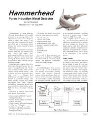
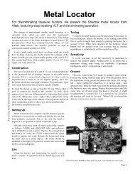
COINSHOOTER<br />
<strong>Metal</strong> <strong>Detector</strong><br />
by William Lahr<br />
Searching for coins and other lost articles along beaches and in parks can be both profitable and fun. The<br />
<strong>Coinshooter</strong>, a novel and inexpensive electronic metal detector, can make such outings more productive. Employing<br />
a sophisticated, VLF induction-balance detection system that responds only to the proximity of nonferrous metallic<br />
objects, it ignores items containing iron. Moreover, the project can be adjusted to compensate for the soil’s mineral<br />
content, thus minimizing false indications.<br />
The <strong>Coinshooter</strong> can detect a dime at an air gap of four inches or a half-dollar at nine inches. It cannot detect coins<br />
buried deep in the ground, but will yield excellent results if the coins are at depths of from 1 to 3 inches. Unlike<br />
detectors that employ conventional beat-frequency oscillator circuits, the <strong>Coinshooter</strong> does not require the user to<br />
monitor the pitch of a continuous tone. Rather, it alerts the user to the proximity of nonferrous metal by generating<br />
one or more beeps. Also, it is lightweight (about 2 lb.) and well balanced. Total construction cost is approximately<br />
$35, and less if salvaged parts are used.<br />
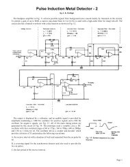
About the Circuit. The <strong>Coinshooter</strong> appears schematically in Figure 1. Coplanar search coils are formed by placing<br />
a receiving coil (L3) over a folded-loop transmitting coil (L1 and L2) so that there is little if any coupling between<br />
them unless there is metal present in the search field. A Colpitts oscillator comprising Q1 and its associated passive<br />
components generates a 6.2-kHz signal that drives the transmitting coil. Transistors Q2 and Q3 amplify the lowlevel<br />
signal induced across receiving coil L3 when no metal objects are present in the search field so that a 1-volt pp<br />
signal appears at the collector of Q3.<br />
Capacitor C7 couples this signal to the non-inverting input of voltage comparator IC1A. The input circuit of the<br />
comparator rectifies the ac signal, resulting in the generation of a slightly negative voltage that subtracts from the<br />
positive bias voltage supplied by divider R13-R14. Potentiometers R29 and R30 determine the magnitude of the<br />
reference voltage applied to the inverting input of ICIA and hence the detector circuit’s sensitivity. They are<br />
adjusted so that the voltages at the two inputs are practically equal.<br />
When the voltage at the non-inverting input of the comparator becomes more positive than that at the inverting<br />
input, the output terminal (pin 1) switches to the positive supply voltage. This positive pulse toggles comparators<br />
IC1B and IC1C, which are connected in.cascade and whose inverting inputs are biased to one-half the positive<br />
supply voltage. The charging of C9 via D1 and the discharging of C9 through R19 stretches the pulse. Transistor Q4<br />
is triggered into conduction by the elongated pulse that appears at the output of IC1C, cutting off Q5.<br />
When Q5 is cut off, Q6 amplifies the tone produced by the audio oscillator comprising IC1D and its associated<br />
passive components. The current flowing through the primary of audio-output transformer T1 and transistor Q6<br />
increases the voltage drop across R5, and this upsets the bias applied to the inverting input of IC1A. As a result, the<br />
outputs of IC1A, IC1B, and IC1C go low, transistor Q4 cuts off, and transistor Q5 saturates, shunting the base drive<br />
of Q6 to ground and cutting that transistor off. This silences the loudspeaker and allows C8 to charge again to the<br />
full positive supply voltage. The higher voltage across the capacitor allows IC1A to change state again if the<br />
nonferrous metal object is still within the search field.<br />
Iron objects or mineralized ground within the search field will produce an increase in the amplitude of the signal at<br />
the collector of Q3 and thus a less positive bias at the non-inverting input of IC1A. In contrast, the presence of coins<br />
or other. nonferrous metal objects within the search field will cause a smaller signal to appear at the collector of Q3<br />
and a more positive bias at the non-inverting input of the first voltage comparator. This allows the <strong>Coinshooter</strong> to<br />
locate coins and other items of interest while ignoring nails, bottle caps, and other junk pieces of iron and steel.<br />
When a small nonferrous item quickly enters and exits the search field, the loudspeaker will generate a single beep.<br />
If the object enters and remains in the search field, a series of beeps will be produced. Its rate of repetition will vary<br />
Page 1
B1,B2 9v alkaline battery<br />
C1 0.033 μF, 50v Mylar capacitor<br />
C2, C10 0.022 μF, 50v Mylar capacitor<br />
C3, C9 1 μF, 16v tantalum capacitor<br />
C4 0.01 μF, 50v ceramic disc capacitor<br />
C5 0.005 μF, 50v ceramic disc capacitor<br />
C6, C8, C12 10 μF, 18v aluminum electrolytic<br />
capacitor<br />
C7 0.1 μF, 50v Mylar capacitor<br />
C11 0.002 μF, 50v ceramic disc capacitor<br />
D1, D2 1N914 silicon switching diode<br />
IC1 LM339 quad voltage comparator<br />
IC2 LM340T-8 +8v regulator<br />
L1, L2 Air-core inductor: 175 turns of No. 30<br />
wire wound 9-1/2 inches in diameter (see<br />
text)<br />
L3 Air-core inductor: 550 turns of No. 38<br />
enamelled wire on 3-1/2" diam.<br />
Q1 2N3906 or similar pnp silicon switching<br />
transistor<br />
Q2 through Q6 2N2222 or similar npn silicon switching<br />
transistor<br />
The following, unless otherwise specified, are 1/4 watt, 5%tolerance,<br />
carbon composition fixed resistors.<br />
R1 5.6 kΩ<br />
R2, R19, R26 22 kΩ<br />
R3 2.2 kΩ<br />
R4 100Ω<br />
R5 470Ω<br />
R6 82 kΩ<br />
R7 1 kΩ<br />
R8 470 kΩ<br />
R9 3.3 kΩ<br />
R10 680Ω<br />
R11 220Ω<br />
R12, R14, R17, R18 4.7 kΩ<br />
R13, R15, R16, R20, R21, R23 10 kΩ<br />
R22 1 MΩ<br />
R24, R27 100 kΩ<br />
R25 220 kΩ<br />
R28 56 kΩ<br />
R29 5 kΩ, linear-taper potentiometer<br />
R30 5 kΩ, linear-taper potentiometer with<br />
shaft-actuated SPST switch<br />
S1 SPST switch (part of R30)<br />
SPKR 2-1/4 inch, 8Ω dynamic speaker<br />
T1 1kΩ:8Ω miniature audio output<br />
transformer<br />
Misc. - Suitable enclosure, perforated or printed-circuit board, single-conductor shielded cable, hookup wire, No. 30 and No. 38<br />
enamelled copper magnet wire, battery clips, battery holders, circuitboard standoffs, grommets or other suitable strain reliefs for<br />
shielded cable, PVC electrical tape or silicone cement or other suitable insulating material, 12-inch-by-12-inch sheet of 1/4-inch<br />
plywood, monofilament fishing line, 3/4-inch masking tape, epoxy, hot-melt, and PVC glues, 4 feet of 1/2-inch O.D., schedule<br />
125 PVC pipe, 2 feet of 1/2-inch, schedule 40 PVC pipe, 90° elbow PVC pipe joint, 135° elbow PVC pipe joint, tee PVC pipe<br />
joint, PVC pipe cap, bicycle steering-bar handgrip, lead buckshot, resin sealant, white paint, solder, hardware, aluminum foil etc.<br />
Page 2
with the settings of potentiometers R29 and R30, the size of the object, and the distance between the object and the<br />
search coil. The pitch of the beep is determined by the values of C11 and the resistances in the feedback loop, as<br />
well as by the supply voltage. Its frequency is nominally 1.3 kHz.<br />
Power for the <strong>Coinshooter</strong> circuit is supplied by two series-connected nine-volt batteries. An IC voltage regulator<br />
provides a constant supply potential to the rest of the circuit until the batteries are nearly exhausted. Quiescent<br />
current demand is approximately 10 mA, so battery replacement should be infrequent if alkaline cells are used. If<br />
desired, the <strong>Coinshooter</strong> can be powered by a single nine-volt battery and the regulator IC omitted. However, the<br />
circuit is sensitive to changes in supply voltage, and this alternative is not recommended. But, if this approach is<br />
taken, an alkaline battery must be used.<br />
Construction. Procure a circular form 9-1/2" in diameter on which you can wind the transmitting coil. In<br />
assembling the prototype, a hamper lid was used, but a mixing bowl or cardboard cylinder would be suitable. Wind<br />
a layer of masking tape 3/4-inch wide around the form so that the adhesive side is exposed. The tape will hold the<br />
wire and make winding the coil much easier. Wind a total of 175 turns of No. 30 enamelled copper wire around the<br />
form, keeping the wire as close to the center of the tape as possible. The last turn should exit the coil at a point on<br />
the circumference 10 inches before the starting point is reached. Fold the tape around the coil and remove it from the<br />
form. Spiral-wrap the coil tightly with masking tape. Then shape the coil assembly as shown in Fig. 2 to form the<br />
transmitting coil. (L1 is the large-diameter portion and L2 is the small-diameter section.) The coils must be shielded<br />
so spiral wrap them (starting with L1 opposite the lead wires) with 1" wide strips of aluminum foil. Cover the coils<br />
completely except for a 1/4" gap between start and finish of the foil layer. Strip a 6" piece of hookup wire and lay it<br />
on the foil so that 2" exits next to one of the lead wires. Then spiral wrap the coils tightly with masking tape,<br />
covering the foil completely.<br />
Page 3
Next, cut a disc seven inches in diameter from a sheet of 1/4-inch plywood. Lay the shaped coil assembly on the disc<br />
and trace pencil lines around the inside of L1 and both sides of L2 (see Fig. 3). Remove the coil assembly and drill a<br />
series of 1/16-inch holes spaced 1/2 inch apart along the pencil lines. Then place the shaped coil assembly back on<br />
the disc and tie it down with monofilament fishing line, looping the line through the series of holes.<br />
Obtain a circular form 3-1/2 inches in diameter on which you can wind the receiving coil. In assembling the<br />
prototype, a glass ashtray was used, but a cardboard cylinder would also be acceptable. The form should have a<br />
slight taper to facilitate removal of the coil after it has been wound. Apply masking tape to the form as was done in<br />
winding the transmitting coil, and wind 550 turns of No. 38 enamelled copper wire, keeping the windings as close to<br />
the center of the tape as possible. When the coil has been wound, fold the tape around the windings and remove the<br />
coil from the form. Spiral-wrap the coil tightly with masking tape. Wrap the coil with foil and another layer of tape<br />
as on L1 and L2 being sure to cover the foil completely. If the two foil shields are allowed to touch when the coils<br />
are positioned, the detector will not function.<br />
Now assemble the circuit of the <strong>Coinshooter</strong>. In the construction of the prototype, a small (5 inches by 1-3/4 inches)<br />
perforated board and point-to-point wiring were used. Printed circuit assembly techniques are also acceptable.<br />
Because the circuit operates at very low frequencies, parts layout is not especially critical. Use an IC socket or<br />
Molex Soldercons for IC1 rather than soldering the chip's pins directly to the circuit board.<br />
Potentiometer· R29 and R30 and the loudspeaker are not mounted on the board. Rather, they should be affixed to the<br />
enclosure housing the circuit board. Resistor R11 can be soldered directly across the outer lugs of potentiometer<br />
R29. A total of four holes (two 3/8 inch in diameter spaced 2 inches apart, and two 1/8 inch in diameter spaced 1/2<br />
inch above and below the larger holes) should be drilled in the bottom of the project enclosure so that two shielded<br />
cables can exit the enclosure and self-tapping screws can provide mechanical support. Additional holes might have<br />
to be drilled for circuit-board standoffs.<br />
Prepare the inner conductor and shield at one end of each of two 48-inch lengths of single-conductor shielded cable.<br />
Color-code both ends of one of the cables with a dab of enamel paint or nail polish. Connect the shields of the<br />
prepared ends of both cables to circuit ground. The inner conductor of the color-coded cable should be connected to<br />
the node C1, C2, and collector of Ql; the inner conductor of the other cable should be connected to the node C4, C5.<br />
These cables should exit the enclosure housing the circuit board through the two 3/8-inch holes previously<br />
drilled through its bottom. Be sure to outfit these holes with grommets or similar bushings that prevent chafing of<br />
their outer plastic jackets and that provide strain relief.<br />
When the circuit board has been assembled and mounted in the enclosure along with the other components, place the<br />
transmitting-coil assembly and the receiving coil on a desk or on the door away from any metal. Prepare the free<br />
ends of the two shielded cables and tin their inner conductors and shields. Using clip leads, connect the color-coded<br />
cable's conductors to the transmitting coil, and the other cable's conductors to the receiving coil. Connect the coil<br />
shields to the outer cable conductors. Apply power to the circuit and connect an oscilloscope probe between Q3's<br />
collector and circuit ground.<br />
Referring to Fig. 4, position the receiving coil near the center of the plywood disc on which the transmitting coil has<br />
been mounted. Adjust the position of the receiving coil for the minimum signal level at the collector of Q3 as<br />
indicated by the scope beam's vertical deflection. Trace a pencil line on each side of the receiving coil after the null<br />
position has been determined, and then remove the receiving coil from the disc. Drill a series of 1/16-inch holes,<br />
spaced 1/2 inch apart, along the pencil lines. Reposition the receiving coil on the disc and tie it down with<br />
monofilament fishing line, looping the line through the small holes.<br />
Using hot-melt or epoxy glue, cement a 135° elbow PVC pipe joint in the area between L2 and L3 so that its open<br />
end points toward the gap in L1. (See Fig. 5.) Cut a 39-inch length of 1/2-inch O.D., schedule 125 PVC pipe, and<br />
drill four 1/4-inch holes in it, one above the other, approximately 2 inches in from each end. The two holes at one<br />
end of the pipe section should be 2 inches apart from each other, but the holes at the other end can be closer. Also<br />
drill two 1/8-inch holes spaced 1/2 inch above and below the two holes spaced 2 inches apart.<br />
Page 4
Slip the free ends of the shielded cables exiting the circuit-board enclosure through the 1/4-inch holes that are<br />
bracketed by the smaller holes and pass the cables through the pipe until they protrude from the far end. Run a bead<br />
of hot-melt or epoxy glue on the pipe and attach the bottom of the project enclosure to the pipe. Added mechanical<br />
support can be introduced by driving self-tapping screws through the two small holes in the bottom of the enclosure<br />
and into the matching holes that were drilled into the pipe section.<br />
Feed the free ends of the shielded cables through the two holes at the other end of the pipe. Insert that end of the<br />
pipe into the elbow joint attached to the plywood disc so that the circuit enclosure faces away from the coil<br />
assembly. Then glue the pipe to the elbow joint using PVC cement, maintaining the orientation of the enclosure with<br />
respect to the coil assembly. (Note that PVC cement sets quickly.) Solder the conductors of the color-coded cable to<br />
the transmitting coil and the conductors of the other cable to the receiving coil. The polarities of these connections<br />
are unimportant. Connect the coil shield leads to the outer cable conductors. Insulate the solder joints using PVC<br />
electrical tape, silicone cement, or some other suitable material. Then cement the cables to the plywood disc in the<br />
area between L3 and the gap in L1 using hot-melt or epoxy glue.<br />
Cut 6- and 9-inch lengths of 1/2-inch O.D., schedule 40 PVC pipe. Assemble a handle using the lengths of pipe, a<br />
90° elbow PVC pipe joint, a tee PVC pipe joint, a bicycle steering-bar handgrip and PVC cement. The handgrip is<br />
glued to the 9-inch section of pipe, and one of the two collinear openings of the tee should be glued to the 39-inch<br />
pipe section to which the circuit-board enclosure and the search coil assembly are attached. PVC cement is fastsetting,<br />
so work quickly and orient the handle such that it is directly above the circuitboard enclosure. The remaining<br />
end of the tee will be left open until the detector is balanced.<br />
Apply power to the circuit and reconnect the oscilloscope probe between the collector of Q3 and circuit ground.<br />
Suspend the search coil in the air away from any metal and rotate the shaft of R29 to its minimum-sensitivity setting.<br />
Monitor the scope trace and, if necessary, slightly adjust the position of L3 so that a 1-volt p-p signal appears at the<br />
collector of Q3. Pass a pair of pliers approximately three inches under the search-coil assembly while monitoring the<br />
scope trace. If the signal level decreases, shift L3 through the null point and repeat the test. The signal must increase<br />
in amplitude when the pliers are brought near the search-coil assembly, or the detector will ignore coins and respond<br />
to the proximity of ferrous objects. Receiving coil L3 should be positioned as close to the null point as possible yet<br />
still provide an increase in signal amplitude when iron or steel is brought near the search-coil assembly.<br />
Next, pass a dime about three inches under the search coil and note the slight increase in signal level as displayed on<br />
the oscilloscope. Carefully fix the positions of the coils by bonding them to the plywood disc with quick-setting<br />
epoxy cement. When the epoxy has cured, remove the scope probe and button up the circuit-board enclosure.<br />
Advance the setting of the SENSITIVITY control until the speaker begins to beep. Then adjust the FINE TUNE<br />
control to silence the speaker. Pass a pair of pliers three inches below the search coil and note that the speaker<br />
remains silent. Then pass a dime three inches under the coil and note that the speaker starts to beep. The most<br />
sensitive area of the search coil is near its center.<br />
The search-coil assembly can be coated with two thin applications of resin to seal it, and then it can be painted white<br />
so that it matches the PVC pipe. The coils must be bonded securely to the disc before the application of sealant and<br />
paint. To minimize the possibility of displacing the coils, use spray-on resin and paint.<br />
If the coils have shifted position before the resin has cured, a compensating piece of iron or steel can be added to the<br />
search-coil assembly. Determine whether this has in fact happened by removing the top of the circuit-board<br />
enclosure and reconnecting the oscilloscope probe between the collector of Q3 and circuit ground. Pass a ferrous<br />
object three inches below the search coil and monitor the scope trace. If the proximity or iron or steel causes a<br />
decrease in signal level, position a small steel washer on or near receiving coil L3 to correct for the misalignment.<br />
Locate the required position by repeating the test for iron sensitivity and shifting the location of the washer until the<br />
correct response is obtained. Then fix the washer in place with epoxy cement.<br />
Final Assembly and Use. Grasp the <strong>Coinshooter</strong> by its handgrip and check it for proper balance. The search-coil<br />
assembly should be parallel with and approximately 2 inches above the floor. Cut a 3-inch piece of 1/2-inch O.D.,<br />
Page 5
schedule 125 PVC pipe, and glue one end of it to a PVC pipe cap. Fill the pipe section with lead buckshot and tape<br />
its open end closed with PVC electrical tape. Then tape the shot-laden pipe section to the open end of the tee PVC<br />
pipe joint and recheck the balance of the project.<br />
If it is unbalanced, untape the shot-laden pipe section, remove a little shot, tape the section closed again and reattach<br />
it to the tee PVC pipe joint. Recheck the balance of the <strong>Coinshooter</strong>. If necessary, repeat this procedure until the<br />
<strong>Coinshooter</strong> is properly balanced and feels comfortable to the hand. When the correct amount of shot has been<br />
determined, remove the pipe section from the tee PVC pipe joint, seal the shot in the pipe section with epoxy, and<br />
cement the section to the tee after the epoxy has cured. This completes assembly.<br />
Take the finished project outdoors and hold the search coil 4 to 6 inches above the ground. Apply power to the<br />
project and adjust its controls so that the speaker emits a slow series of beeps. Lower the search coil until it is<br />
approximately 2 inches above the ground. The beeping should stop. This occurs because most soil is mineralized<br />
and affects the <strong>Coinshooter</strong> much like ferrous objects do.<br />
The detector is now at maximum sensitivity and will detect coins at depths of from 1 to 3 inches, depending on their<br />
sizes and positions. Ferrous objects will not trigger the circuit unless they are very large or very close to the search<br />
coil or both. The <strong>Coinshooter</strong> will detect aluminum cans, caps and pull tabs, but it responds best to coins. Raise the<br />
search coil from time to time to check for the slow beeps that indicate maximum detector sensitivity. Although the<br />
circuit is very stable, the FINE TUNE control might have to be adjusted occasionally to compensate for changes in<br />
ground mineralization, temperature, and, if an unregulated power supply is used, battery voltage.<br />
Always hold the <strong>Coinshooter</strong> so that the search-coil assembly is 1 to 2 inches above and parallel to the ground. Try<br />
to keep the search coil at a constant height above the ground. Swing the loop back and forth in front of you, making<br />
overlapping arcs. It is best to search slowly, but a coin will usually be detected even if the search coil passes over it<br />
quickly. For best results, operate the circuit as close to its switching threshold as possible.<br />
When an object has been detected, move the search-coil assembly over it from front to back and from side to side to<br />
pinpoint its location. Keep in mind that the center oft assembly is its most sensitive point. Probe for the object with a<br />
small screwdriver or similar digging tool. If you search for coins in parks and woodlands, do so without disturbing<br />
the landscape. Always fill any holes that you make with your digging tool and place any turf that has been disturbed<br />
back in its original position.<br />
Page 6