INDUCTION BALANCE METAL DETECTOR - Geotech
INDUCTION BALANCE METAL DETECTOR - Geotech
INDUCTION BALANCE METAL DETECTOR - Geotech

Create successful ePaper yourself
Turn your PDF publications into a flip-book with our unique Google optimized e-Paper software.
Murray/Modern Magazines, reproduce for personal use only<br />
ETI: How To Build Gold & Treasure Detectors, 1981 — Copyright ©<br />
Project 549<br />
<strong>INDUCTION</strong> <strong>BALANCE</strong><br />
<strong>METAL</strong> <strong>DETECTOR</strong><br />
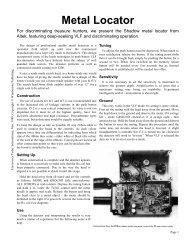
A really sensitive design operating on a different principle from that of other<br />
published circuits. This ‘Induction Balance’ metal locator will really sniff out<br />
those buried coins and other items of interest at great depths (depending on<br />
the size of the object).<br />
Another metal locator, some of you<br />
will say. Yes and no. Several designs<br />
have been published in hobby electronics<br />
magazines around the world, some<br />
good, some downright lousy, but they<br />
have invariably been Beat Frequency<br />
Oscillator (BFO) types. There’s nothing<br />
wrong with this principle — they<br />
are at least easy to build and simple to<br />
set up. The design described here works<br />
on a very different principle, that of<br />
induction balance (IB). This is also<br />
known as the TR principle (Transmit-<br />
Receive).<br />
First a word of warning. The electronic<br />
circuitry of this project is<br />
straightforward and should present no<br />
difficulty even to the beginner. However,<br />
successful operation depends<br />
almost entirely upon the construction of<br />
the search head and its coils. This part<br />
should account for about three-quarters<br />
of the effort in construction. Great care,<br />
neatness and patience is necessary and a<br />
sensitive ‘scope, though not absolutely<br />
essential, is very useful. It has to be<br />
stated categorically that sloppy construction<br />
of the coil will (not may)<br />
invalidate the entire operation.<br />
IB Versus BFO<br />
The usual circuit for a metal locator is<br />
shown in Fig. 2a. A search coil, usually<br />
150 mm or so in diameter is connected<br />
in the circuit to oscillate at between 100<br />
and 150 kHz. A second internal oscillator<br />
operating on the same frequency is<br />
included and a tiny part of each signal is<br />
taken to a mixer and a beat note is pro-<br />
duced. When the search coil is brought<br />
near metal, the inductance of the coil is<br />
changed slightly, altering the frequency<br />
and thus the tone of the note. A tone is<br />
produced continually when the instrument<br />
is in use and metal is identified by<br />
a frequency change in the audio tone.<br />
The IB principle, however, uses two<br />
coils arranged in such a way that there<br />
is virtually no inductive pick-up<br />
between them. A modulated signal is<br />
fed into one. When metal is brought<br />
near, the electromagnetic field is disturbed<br />
and the other coil picks up an<br />
appreciably higher signal.<br />
Ideally the instrument is initially set<br />
up for no pick-up in the ‘receiver’ coil,<br />
but this is impossible in practice — the<br />
two coils are after all laid on top of each<br />
other. Another problem is that our ears<br />
are poor at identifying changes in audio<br />
level. The circuit is therefore arranged<br />
so that the signal is gated and is set up<br />
so that only the minutest part of the signal<br />
is heard when no metal is present.<br />
When the coils are near metal, a minute<br />
change in level becomes an enormous<br />
change in volume.<br />
BFO detectors are not as sensitive as<br />
IB types and have to be fitted with a<br />
Faraday screen (beware of those which<br />
aren’t — they’re practically useless) to<br />
reduce capacitive effects on the coil.<br />
They are however, slightly better than<br />
IB types when it comes to pin-pointing<br />
exactly where the metal is buried.<br />
Our detector is extremely sensitive —<br />
in fact a bit too sensitive for some applications!<br />
For this reason we’ve included<br />
<strong>Geotech</strong> Page 1
Murray/Modern Magazines, reproduce for personal use only<br />
ETI: How To Build Gold & Treasure Detectors, 1981 — Copyright ©<br />
a high-low sensitivity switch. You may<br />
ask why low sensitivity is useful. As a<br />
crude example, take a coin lying on a<br />
wooden floor: on maximum sensitivity<br />
the detector will pick up the nails, etc.,<br />
and give the same readings as for the<br />
coin, making it difficult to find.<br />
Treasure hunting is an art and the<br />
dual sensitivity may only be appreciated<br />
after trials.<br />
Table 1 gives the distances at which<br />
various objects can be detected. These<br />
are static readings and only give an<br />
indication of range. If you are unimpressed<br />
with this performance you<br />
should bear two things in mind: first<br />
compare this with any other claims<br />
(ours are excellent and honest) and secondly<br />
bear in mind how difficult it is to<br />
dig a hole over 1 ft of ground every<br />
time you get a reading. Try it — it’s<br />
hard work!<br />
Component Choice<br />
We have specified Q1 and Q2 types<br />
as BC549C (highest gain group) for<br />
although lower gain transistors worked<br />
for us, they left little reserve of level on<br />
RV1 and really low gain types may not<br />
work at all.<br />
<strong>Geotech</strong> Page 2
Murray/Modern Magazines, reproduce for personal use only<br />
ETI: How To Build Gold & Treasure Detectors, 1981 — Copyright ©<br />
Q5, Q6 and associated components form<br />
the transmitter section of the circuit. Q6 is<br />
a P.U.T. which operates as a relaxation<br />
oscillator, the audio note produced being<br />
determined by R16 and C18. The specified<br />
components give a tone of toughly 800 Hz.<br />
Q5 is connected as Colpitt’s oscillator<br />
working at a nominal 130 kHz; this signal<br />
is heavily modulated by C17 feeding to the<br />
base of Q5. In fact the oscillator produces<br />
bursts of r.f. at 800 Hz. L1 in the search<br />
head is the transmitter coil.<br />
L2 is arranged in the search head in such<br />
a way that the minimum possible signal<br />
from L1 is induced into it (but see notes on<br />
setting up). On all the prototypes we made<br />
we reduced this to about 20 mV peak-topeak<br />
in L2. L2 is tuned by C5 and C6 and<br />
peaked by CV1 and feeds to the base of<br />
Q1, a high gain amplifier. This signal<br />
(which is still modulated r.f.) is detected by<br />
D1, and D2. The r.f. is eliminated by C8<br />
and connects to the level control RV1.<br />
The signal is amplified by Q2 and then<br />
further amplified by Q3 which has no d.c.<br />
bias connected to the base. In no-signal<br />
conditions this will be turned off totally<br />
and will only conduct when the peaks of<br />
the 800 Hz exceed about 0.6V across R5.<br />
Only the signal above this level is<br />
amplified.<br />
On low sensitivity these peaks are connected<br />
to the volume control RV2 (any<br />
stray r.f. or very sharp peaks being<br />
smoothed by C21) and fed to the IC amplifier<br />
and so to the speaker.<br />
The high sensitivity stage Q4 is connected<br />
at all times and introduces another<br />
gating stage serving the same purpose as<br />
the earlier stage of Q3. This emphasises the<br />
How It Works — ETI 549<br />
change in level in L2 even more dramatically.<br />
Note that RV1 has to be set<br />
differently for high and low sensitivity settings<br />
of SW1.<br />
Whichever setting is chosen for SW1.<br />
RV1 is set so that a signal can just be<br />
heard. In practice it will be found that<br />
between no-signal and moderate-signal<br />
there is a setting for RV1 where a ‘crackle’<br />
can be heard. Odd peaks of the 800 Hz find<br />
their way through but they do not come<br />
through as a tone. This is the correct setting<br />
for RV1.<br />
The stage Q4 also feeds the meter circuit.<br />
Due to the nature of the pulses this<br />
need only be very simple.<br />
Since we are detecting really minute<br />
changes in level it is important that the supply<br />
voltage in the early stages of the<br />
receiver are stabilised, for this reason ZD1<br />
is included to hold the supply steady independent<br />
of battery voltage (which will fall<br />
on high output due to the current drawn by<br />
IC1).<br />
It is also important that the supply voltage<br />
to Q5 and Q6 does not feed any signal<br />
through to the receiver. If trouble is experienced<br />
(we didn’t get any) a separate 9V<br />
battery could be used to supply this stage.<br />
IC1 is being well underused so a heatsink<br />
is unnecessary.<br />
Battery consumption is fairly high on<br />
signal conditions — between 60 mA and<br />
80 mA on various prototypes but this will<br />
only be for very short periods and is thus<br />
acceptable. A more modest 20 mA or so is<br />
normal at the ‘crackling’ setting.<br />
Stereo headphones are used and are connected<br />
in series to present 16 ohms to IC1<br />
reducing current consumption.<br />
RV1 is the critical control and should<br />
be a high quality type — it will be<br />
found that it has to be set very carefully<br />
for proper operation.<br />
The choice of an LM380 may seem<br />
surprising as only a small part of its<br />
power can be utilised with battery operation.<br />
It is however inexpensive and<br />
widely available unlike the alternatives<br />
(note it does not require dc blocking at<br />
the input).<br />
Output is connected for an 8 ohm<br />
speaker and to headphones. Stereo types<br />
are the most common and the wiring of<br />
the jack socket is such that the two sections<br />
are connected in series presenting<br />
a 16 ohm load (this reduces current consumption<br />
from the battery).<br />
Construction:Control Box<br />
The majority of the components are<br />
mounted on the PCB overlay and the<br />
additional wiring is shown in Fig. 4.<br />
Exceptional care should be taken to<br />
mount all components firmly to the<br />
board. Poor connections or dubious solder<br />
joints may be acceptable in some<br />
circuits — not in this one. Take care to<br />
mount the transistors, diodes and electrolytic<br />
capacitors the right way around.<br />
The PCB is fitted into the control box<br />
by means of 6 mm spacers. The control<br />
box has to be drilled to take the speaker,<br />
the pots, switches, headphone jack and<br />
the cable from the search head.<br />
The Handle Assembly<br />
The handle we used was simply a<br />
broom handle with the end cut off at<br />
about 45°. After assembling the head,<br />
the handle can be glued on with epoxy.<br />
A small woodscrew can be used to hold<br />
it in place until dry. This should be done<br />
before final setting up of the coils — in<br />
case the screw cannot be removed after<br />
the glue has set.<br />
The Coil<br />
Remember this is the key to the<br />
whole operation. The casing of the coil<br />
is not so critical but the layout is.<br />
It is best first to make the 6 mm plywood<br />
circle to the dimensions shown in<br />
Fig.6. A circle of thinner plywood or<br />
hardboard is then firmly glued onto this<br />
— it’s fairly easy to cut this after glueing.<br />
Use good quality ply and a modern<br />
wood glue to make this.<br />
<strong>Geotech</strong> Page 3
Murray/Modern Magazines, reproduce for personal use only<br />
ETI: How To Build Gold & Treasure Detectors, 1981 — Copyright ©<br />
This now forms a dish into which the<br />
coils are fitted.<br />
You’ll now have to find something<br />
cylindrical with a diameter of near<br />
enough 140 mm (5½ in). A coil will<br />
then have to be made of 40 turns of 32<br />
swg enamelled copper wire. The wire<br />
should be wound close together and<br />
kept well bunched and taped to keep it<br />
together when removed from the<br />
former. Two such coils are required.<br />
These are identical.<br />
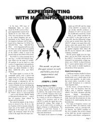
One of the coils is then fitted into the<br />
dish and spot glued in six or eight<br />
places using quick setting epoxy resin:<br />
see photograph.<br />
L2 is then fitted into place, again spot<br />
glueing (not in the area that it overlaps<br />
L1). The cable connecting the coil to<br />
the circuit is then fed through a hole<br />
drilled in the dish and connected to the<br />
four ends. These should be directly<br />
wired and glued in place, obviously taking<br />
care that they don’t short. The cable<br />
must be a four-wire type with individual<br />
screens — the screens are left<br />
unconnected at the search head.<br />
You will now need the built up control<br />
box and preferably a ‘scope. The<br />
transmit circuit is connected to L1. The<br />
signal induced into L2 is monitored; at<br />
first this may be very high but my<br />
manipulating L2 the level will be seen<br />
to fall to a very low level. When a very<br />
low level is reached, spot glue L2 until<br />
only a small part is left for bending.<br />
Ensure that when you are doing this<br />
that you are as far away from any metal<br />
as possible but that any metal used to<br />
mount the handle to the head is in place.<br />
Small amounts of metal are acceptable<br />
as long as they are taken into account<br />
whilst setting up.<br />
Now connect up the remainder of the<br />
circuit and set RV1 so that it is just<br />
passing through a signal to the speaker.<br />
Bring a piece of metal near the coil and<br />
the signal should rise. If it falls in level<br />
(i.e. the crackling disappears) the coil<br />
has to be adjusted until metal brings<br />
about a rise with no initial falling. CV1<br />
should be adjusted for maximum signal,<br />
this has to be done in conjunction<br />
with RV1. The additional capacitors C1,<br />
C2 and C4 should be linked in, if the<br />
range is not available on CV1.<br />
Monitoring this on a scope may mean<br />
<strong>Geotech</strong> Page 4
Murray/Modern Magazines, reproduce for personal use only<br />
ETI: How To Build Gold & Treasure Detectors, 1981 — Copyright ©<br />
that the induced signal is not at its absolute<br />
minimum: this doesn’t matter too<br />
much. Now add more spot glueing<br />
points to L2.<br />
You should now try the metal locator<br />
in operation. If RV1 is being operated<br />
entirely at the lower end of its track,<br />
making setting difficult, you can select<br />
a lower gain transistor such as a BC548<br />
for Q2.<br />
When you are quite certain that no<br />
more manipulation of the coils will<br />
improve the performance, mix up plenty<br />
of epoxy resin and smother both coils,<br />
making certain that you don’t move<br />
them relative to each other.<br />
The base plate can then be fitted to<br />
enclose the coils, this should be glued in<br />
place.<br />
If after glueing in place the balance<br />
<strong>Geotech</strong> Page 5
Murray/Modern Magazines, reproduce for personal use only<br />
ETI: How To Build Gold & Treasure Detectors, 1981 — Copyright ©<br />
between the coils is found to be not<br />
quite tight it should be possible to glue<br />
a small piece of metal (such as a<br />
washer) somewhere on the head to cancel<br />
out the error.<br />
Using The Metal Locator<br />
You will find that finding buried<br />
metal is rather too easy. 95% will be<br />
junk — silver paper being a curse. The<br />
search head should be panned slowly<br />
over the surface taking care to overlap<br />
each sweep. The sensitive area is somewhat<br />
less than the diameter of the coil.<br />
This type of locator will also pick up<br />
some materials which are not metal —<br />
especially coke And it is not at its best<br />
in wet grass.<br />
Think very carefully about where you<br />
want to search: this is more important<br />
than actually looking. The area you can<br />
cover thoroughly is very, very small,<br />
but this approach is far more successful<br />
than nipping all over the place. As an<br />
example of how much better a thorough<br />
search is, we thoroughly tried on<br />
25 square feet of common ground (5ft x<br />
5ft); we found over 120 items but a<br />
quick search initially had revealed only<br />
two!<br />
Treasure hunting is growing in popularity<br />
and those who do it seriously have<br />
adopted a code; essentially this asks you<br />
to respect other people’s property, to fill<br />
in the holes you dig and to report any<br />
interesting finds to museums.<br />
Meter Circuit<br />
Since the circuit is basically sensing a<br />
change in audio level, a meter circuit<br />
can be incorporated. For the very first<br />
indication from the ‘crackle’ your ears<br />
are likely to be more sensitive than the<br />
meter but thereafter it will come into its<br />
own.<br />
This part of the circuit is optional and<br />
the components are not included on the<br />
board.<br />
<strong>Geotech</strong> Page 6