MICROCONTROLLER P.I. TREASURE HUNTER - Geotech
MICROCONTROLLER P.I. TREASURE HUNTER - Geotech
MICROCONTROLLER P.I. TREASURE HUNTER - Geotech

You also want an ePaper? Increase the reach of your titles
YUMPU automatically turns print PDFs into web optimized ePapers that Google loves.
<strong>MICROCONTROLLER</strong> P.I. <strong>TREASURE</strong> <strong>HUNTER</strong><br />
MARK STUART<br />
A powerful and stable design that is reliable, easy to assemble set up and operate.<br />
This project is the natural successor to the highly acclaimed and original design featured in the August 1989 issue. This new<br />
version retains all of the good features of the original and brings up to date ideas and technology into the design to produce a more<br />
powerful stable circuit. It is reliable and easy to assemble, and can be set up without any special tools or equipment.<br />
As well as the electronic circuit design, the hardware has been improved, and is available separately or as part of the full kit.<br />
PULSE INDUCTION - GENERAL<br />
The pulse induction (P.I.) method of metal detection relies on the electrical conductivity of buried objects. Thin sectioned material<br />
such as foil is not very conductive and so is largely ignored. Solid objects such as coins, rings, nails, are much more conductive<br />
and are readily detected, as of course are larger objects.<br />
The biggest advantage of pulse induction is that it is virtually free of “Ground Effect” - so much so that it works perfectly with the<br />
search head immersed in fresh or sea water, provided the coil is adequately protected.<br />
The only real disadvantage of this type of detector is that it detects ferrous and non-ferrous metals alike - and cannot discriminate<br />
between different types of metal. This is more than compensated by the sensitivity, simplicity, and ease of use that the P.I. system<br />
offers, and it is a firm choice with detector enthusiasts, especially for beach combing.<br />
The sensitivity of a P.I. detector is determined mainly by the current in the search coil, which also determines the battery life. This<br />
design has been optimised to operate for a sensible length of time from six AA cells, whilst giving a good practical level of<br />
sensitivity - it will detect a new 10p coin at 20cm.<br />
The sensitivity has been optimised for less conductive metals such as gold. This has been done by setting the appropriate pulse<br />
sampling time - and will be explained in detail later.<br />
PULSE INDUCTION - PRINCIPLES<br />
The pulse induction method of detection works by<br />
subjecting objects to a rapidly changing electromagnetic<br />
field. The field is produced by building up a current in a<br />
simple multi-turn search coil, and then forcing the<br />
current to fall very rapidly by switching off the supply.<br />
As the electromagnetic field decays it induces a voltage<br />
back into the coil, and also into objects near the coil.<br />
Poor or non-conductive objects are unaffected, but in<br />
conductive items a current is induced, producing a small<br />
magnetic field which opposes the decay of the original<br />
field. This opposing field means that when near metal,<br />
the magnetic field around the search coil decays in a<br />
different way, and so the voltage induced in the search<br />
coil also differs.<br />
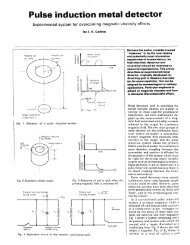
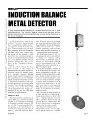
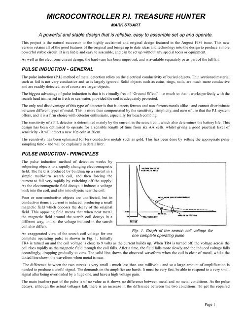
An exaggerated view of the search coil voltage for one<br />
complete operating pulse is shown in Fig. 1. Initially<br />
Fig. 1. Graph of the search coil voltage for<br />
one complete operating pulse<br />
TR4 is turned on and the coil voltage is close to 9 volts as the current builds up. When TR4 is turned off, the voltage across the<br />
coil rises rapidly as the magnetic field through the coil falls. After a time, the field falls more slowly and the induced voltage falls<br />
accordingly, dropping gradually to zero. The solid line shows the observed waveform when the coil is clear of metal, whilst the<br />
dotted line shows the waveform when metal is near.<br />
The difference between the two curves is very small - much less than one millivolt - and so a large amount of amplification is<br />
needed to produce a useful signal. The demands on the amplifier are harsh. It must be very fast, be able to respond to a very small<br />
signal after being overloaded by a huge one, and have a high voltage gain.<br />
The main (earlier) part of the pulse is of no value as it shows no difference between metal and no metal conditions. As the pulse<br />
decays, although the actual voltages fall, there is an increase in the difference between the two conditions. To get the required<br />
Page 1
signal it is necessary to “sample” the waveform at a fixed time after the initial pulse and from this to derive a voltage which can<br />
be used to give an audible or visual output.<br />
The timing of when the sample is taken allows a limited degree of discrimination between different types of metal. A later sample<br />
shows a larger signal for very conductive metals such as copper and silver, whilst an earlier sample (as set in this design) shows a<br />
larger signal for gold (and, unfortunately, aluminium). It is a sad fact that the best setting for jewellery is also that for ring pulls!<br />
DESIGN FEATURES<br />
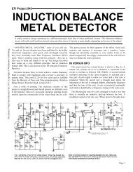
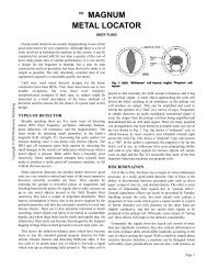
The main objective of this design was to produce a circuit that could be divided easily into sections. This was considered<br />
important because it simplifies fault finding, makes the circuit easier to understand, and most importantly, allows each section to<br />
be optimised for its particular function. Fig. 2 shows the circuit in a simplified functional form.<br />
The use of a microcontroller I.C. (IC5) has allowed all of the vital pulse timing to be optimised, and set in software during<br />
development. All of the timing is set by division from the 4MHz microcontroller clock and so is extremely accurate and free from<br />
jitter and drift which would otherwise appear as noise and reduce the circuit sensitivity.<br />
There are two other particularly important features in this design. The first is the method of drift cancellation which is applied<br />
around IC4. Despite its mundane sounding number, the LM318 is a very fast high gain amplifier which can recover immediately<br />
from large overdrive, and then amplify very small signals without overshoot or “ringing”. To use it to its full benefit in this circuit<br />
it needs to be d.c. coupled and operated at the highest gain possible. With this level of gain. battery voltage and temperature<br />
changes produce significant output voltage shifts, which would mean regular re-adjustment of the frequency control.<br />
To deal with this problem, a novel piece of circuitry has been added. The essential part of this is the combination of R16 and C9.<br />
These act as a low pass filter, removing any pulses and producing at their junction, a smooth d.c. voltage which is the average d.c.<br />
output of IC4.<br />
Two analogue gates IC3b and IC3c (which operate as electronic switches) are switched by the microcontroller in such a way that<br />
the average d.c. voltage from IC4 is subtracted from its direct output - which contains the same d.c. voltage but with the wanted<br />
pulse superimposed upon it. The net result is that the d.c. voltages cancel, leaving just the desired pulse to pass via capacitor C8 to<br />
the rest of the circuit. Since the output no longer contains any d.c., there cannot be any voltage drift.<br />
SAMPLE AND HOLD<br />
Fig. 2 Simplified diagram of the Microcontroller P.I. Treasure Hunter<br />
The second feature is the use of a “sample and hold” circuit to detect the wanted pulse height. Resistor R12 sets the d.c. level at<br />
the output from C8 so that the voltage at the junction of C8 and R12 is the positive supply voltage with the wanted negative going<br />
pulses superimposed upon it. These pulses need to be converted into a steady voltage proportional to their height which can be<br />
used to drive a voltage controlled oscillator to give a variable frequency signal in the headphones.<br />
Page 2
The conventional approach is to use an integrator circuit with a fast charge and slow discharge rate. This does the job, but as the<br />
discharge rate is slow, the circuit is limited in its speed of response. The output also contains a significant amount of the main<br />
operating pulse frequency as the integrator voltage rises and falls each pulse cycle, giving rise to a rough sounding tone in the<br />
headphones.<br />
The sample and hold circuit uses analogue gate IC3a which is switched on only during the wanted pulse. In this time the pulse<br />
voltage is transferred to C6 where it is held during the time that the analogue gate is switched off until the next pulse is sampled.<br />
Any change (increase or decrease) in the height of the wanted pulse is immediately transferred to C6 during the sample period and<br />
held. Between sample pulses then is no path for C6 to discharge (except via the input resistance of IC2a which is practically<br />
infinite) and so the voltage is held perfectly steady.<br />
This is a major improvement over the conventional integrator because it maintains a constant voltage between pulses instead of<br />
drifting slowly. The result is that the frequency heard by the operator sounds smoother, and that the circuit responds very quickly<br />
and equally to increases and decreases in the pulse height as the search coil moves over metal.<br />
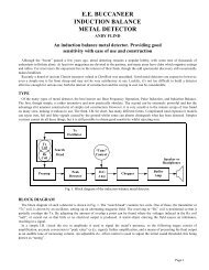
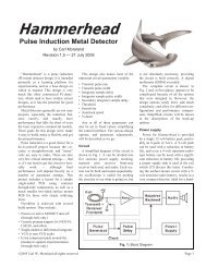
CIRCUIT<br />
The full circuit diagram is shown in Fig.3. It appears very complicated as a whole, but each section is fairly straightforward and<br />
will be described separately. Apart from the main 9 volt battery supply there are two other voltages required by the circuit. The<br />
first is 5 volts for the microcontroller i.c. This is produced by D5, a simple shunt Zener diode regulator fed with around 10mA via<br />
resistor R24. IC5 draws only 2mA and so most of the current passes through D5 giving good solid regulation. Decoupling<br />
capacitor C13 maintains a low supply impedance at high frequency to keep IC5 stable.<br />
The second supply required is higher than the battery voltage and is necessary so that IC2, IC3, and IC4 on be operated with their<br />
inputs and outputs at, or close to, the battery supply voltage. Providing plenty of “headroom” like this is very useful in pulse<br />
circuits as it ensures that clipping and other forms of voltage limited distortion are eliminated.<br />
The supply is provided by a simple voltage doubler circuit built around “Charge Pump” circuit IC6. This type of i.c. is extremely<br />
efficient and versatile, it contains an oscillator driving a number of internal switching devices. In this arrangement C14 is fully<br />
charged via D1 and then switched so that its voltage is added to the battery supply and delivered to smoothing capacitor C15 via<br />
D2.<br />
The circuit operates at 10kHz and so only small capacitor values are needed to give a ripple free output of the 10mA or so<br />
required by the circuit. The two voltage regulators are independent circuit blocks and so will work, and can be tested, on thei r<br />
own.<br />
TIMING AND PULSE GENERATOR<br />
Fig. 2 Full circuit diagram of the Treasure Hunter<br />
The timing and pulse generation is a very simple application for a microcontroller i.c. but the ease with which such a device can<br />
be used to provide carefully timed pulses is justification in itself. Added to that is the benefit of being able to vary the timing<br />
Page 3
during the development simply by altering the software until the optimum<br />
values were achieved. The device is a One Time Programmable (OTP)<br />
chip which has a section of EPROM but without a window. Once<br />
programmed it becomes dedicated to this application.<br />
The timing is derived from the microcontroller clock which is provided<br />
by 4MHz crystal XLI and its associated capacitors C10 and C11. Resistor<br />
R21 ensures that IC5 resets properly and begins running its program<br />
immediately power is applied. There are two pulse outputs, one is to the<br />
main coil switching circuit via R22 and the other to the signal processing<br />
circuits via R17.<br />
Because the microcontroller runs from only 5 volts it is necessary to add<br />
transistors TR2 and TR3 which act as “level shifters” for the pulse<br />
outputs, producing pulses which swing from 0 to 16 volts across their<br />
collector loads R15 and R25.<br />
COIL DRIVE CIRCUIT<br />
The search coil is energised from the 9 volt battery rail. Current is<br />
switched on via a high voltage power MOSFET TR4 which is driven<br />
from IC5 via TR3. The 16 volt positive pulse at the collector of TR3<br />
ensures that TR4 is fully turned on and has a very small voltage drop. The<br />
turn on of TR4 is relatively slow as its gate capacitance is charged via<br />
R25, but the turn off is much quicker because TR3 is turned on and<br />
provides a low resistance path for the gate capacitance to be discharged to<br />
0 volts.<br />
Resistor R28 limits the TR4 gate current during switching, and protects<br />
TR3 in the event of a power device fault. Supply decoupling capacitor<br />
C16 provides a reservoir from which the high pulse current can be drawn<br />
without causing a huge dip in the supply voltage.<br />
The search coil current builds up to several amps during the time that<br />
TR4 is turned on. Immediately after TR4 is turned off a high voltage<br />
positive spike appears across the coil as the current decays via damping<br />
resistors R26 and R27. Diodes D3 and D4 clip the voltage spikes via R26<br />
to less than one volt peak-to-peak. After the spikes, as the voltage decays<br />
into the sampling area, it is way below one volt and the diodes are<br />
completely non conducting and so have no influence on the circuit.<br />
COIL VOLTAGE AMPLIFIER<br />
The clipped coil voltage is amplified by IC4 which has its inverting gain<br />
set by feedback resistor R19 and the effective pulse source resistance R23<br />
+ R26. Feedback capacitor C12 improves the stability and speed. The<br />
non-inverting input of IC4 is connected to the other end of the coil (which<br />
also happens to be the battery positive rail) via R20.<br />
The connection point of R20 is very important, and must be close to the<br />
coil so that IC4 amplifies the difference in voltage between the coil ends,<br />
and does not also get unwanted voltage drops from current drawn in the<br />
rest of the circuit from the battery positive rail.<br />
Preset VR2 and R18 allow the output of IC4 to be set to zero when there<br />
is no input. This adjustment is to compensate for production differences<br />
in the i.c.s input offset voltages and currents and once set should require<br />
no further adjustment. The term “zero” should not be taken literally here,<br />
as both inputs of IC4 are at the positive 9 volt supply rail and VR2 should<br />
be adjusted so that the output is also at this voltage.<br />
Resistors<br />
R1 220<br />
R2 470k<br />
R3, R4, R16 100k (3off)<br />
R5, R6, R8, R10, R12, R13, R15, R17, R21,<br />
R22, R25 10k<br />
R7, R14 150<br />
R9 2k2<br />
R11 3k3<br />
R18 220k<br />
R19 1M<br />
R20, R23 100 (2 off)<br />
R24 330<br />
R26, R27 470 5% 1 watt metal film<br />
R28 56<br />
All 5% carbon film 1/4 Watt except R26 and R27.<br />
Potentiometers<br />
VR1 47k to 220k lin. switched carbon<br />
VR2 220k miniature preset<br />
Capacitors<br />
C1, C4, C13, C14<br />
10u radial elect. 16V (4 off)<br />
C2, C3, C5, C6, C8<br />
100n ceramic multilayer (5 off)<br />
C7 47n ceramic multilayer (5 off)<br />
C9 220n min layer type polyester<br />
C10, C11 33p ceramic plate (2 off)<br />
C12 5p6 ceramic plate<br />
C15 47u elect. 25V<br />
C16 1000u radial elect. 10V<br />
Semiconductors<br />
IC1 ICM7555 low power CMOS timer<br />
IC2 TL072 CP dual BIFET op. amp<br />
IC3 4066 or 4016 quad analogue gate<br />
IC4 LM318 fast bipolar op. amp<br />
IC5 MAGPI-1 programmed<br />
microcontroller (see Shoptalk)<br />
IC6 LMC7660 voltage converter<br />
D1, D2, D3 1N4148 signal diodes (3 off)<br />
D4 BY407A high speed diode<br />
D5 5V1 500mW Zener<br />
TR1 BC213 pnp transistor<br />
TR2, TR3 BC183 npn transistor (2 off)<br />
TR4 IRF840CF high voltage<br />
enhancement mode MOSFET<br />
Miscellaneous<br />
XL1 4MHz crystal<br />
L1 20 metres of 0.71mm diameter<br />
enamelled copper wire for search coil<br />
JK1 3.5mm headphone socket<br />
6 x AA battery holder and connecting clip; case<br />
for control board; knob for VR1; i.c. sockets;<br />
search head, handle, and stem hardware kit.<br />
Printed circuit board available from EPE PCB<br />
Service, code 882.<br />
Page 4
PULSE SEPARATION<br />
The wanted part of the pulse from IC4 is selected by a time delayed signal from IC5 which is coupled via TR2 to analogue gate<br />
IC3b. The timing is such that IC3b is turned on only during the required part of the amplified decaying coil voltage. IC3d is used<br />
to invert the phase of the pulse from TR2 which is then used to drive another analogue gate IC3c which is turned on whenever<br />
IC3b is turned off. IC3c has as its input an average voltage derived from the output of IC4 after filtering by R16 and C9.<br />
The combined output of the two analogue gates IC3b and IC3c consists of the wanted part of the decaying pulse, and in between,<br />
the average d.c. level to which the decaying pulse eventually settles (this has been explained more fully in the Design Features<br />
section). Capacitor C8 removes the d.c. level but passes the pulses, and R12 re-inserts a new d.c. level which is equal to the<br />
battery supply voltage. The signal across R12 is simply negative going pulses, the height of which depends on how much metal is<br />
near to the search coil.<br />
SAMPLE AND HOLD<br />
Analogue gate IC3a is switched so<br />
that it is open during the wanted<br />
signal pulses and closed the<br />
remainder of the time. During the<br />
time that it is open, the wanted pulse<br />
voltage charges C6. Once the gate<br />
closes the voltage on C6 is held<br />
steady because there is no available<br />
discharge path - either back through<br />
the gate, or into the very high input<br />
impedance of IC2a. The result is a<br />
stable voltage that is adjusted to<br />
each new pulse level. If the pulses<br />
do not change in height, the voltage<br />
remains the same.<br />
DC AMPLIFIER AND<br />
V.C.O.<br />
The signal across C6 is further<br />
amplified by IC2a which is<br />
configured as a non-inverting d.c.<br />
amplifier with a gain which is set to<br />
10 by R4 and R5. To allow the<br />
output voltage of IC2a to be<br />
adjusted so that the output signal<br />
tone can be set, a d.c. voltage is<br />
inserted from control VR1 via R3.<br />
Capacitor C3 decouples the<br />
adjusting voltage to ensure that<br />
interference is not introduced.<br />
From IC2a the amplified d.c. signal<br />
is filtered via R2 and C2 and<br />
buffered by IC2b which acts as a<br />
unity gain non-inverting amplifier.<br />
The output is then used to drive TR1<br />
which adjusts the charging current<br />
of C7 and hence the oscillation<br />
frequency of IC1 which is a<br />
standard low power CMOS 555<br />
timer thus providing a voltage<br />
controlled oscillator (v.c.o.).<br />
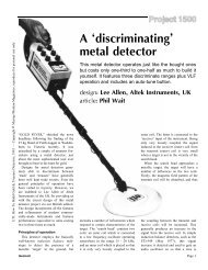
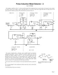
Fig. 4. Printed circuit board design and layout for the Treasure Hunter<br />
Page 5
The output from IC1 is connected to the headphone socket via C1 and R1 and provides more than enough signal for small<br />
personal stereo headphones. Resistor R7 and C4 decouple the supply to make sure that the output signal is clean and does not<br />
interfere with the rest of the circuit.<br />
CONSTRUCTION<br />
The circuit is based on a single printed circuit board, and involves very little wiring. The component layout and copper foil pattern<br />
are shown in Fig. 4. Sockets can be used for all of the i.c.s and make fault finding a lot easier.<br />
Although the circuit is complicated, the final board layout is not overcrowded and is easy to assemble. Before inserting any<br />
components, decide how the board will be fitted into the case, and use it as a template for any case drilling. The prototype board<br />
was mounted by the bush of VR1 without any other support, but space has been allowed on the final board layout for additional<br />
fixing screws, and VR1 may be mounted elsewhere, off the board if an alternative layout is preferred. Remember before drilling<br />
that the board is fitted into the case with its track side down!<br />
The case requires other holes to be drilled to fit two saddle clips, the headphone socket, and for the search coil connecting lead.<br />
The positioning of these is left to individual choice, but it is a good idea to keep the socket and search coil holes facing<br />
downwards in case of rain.<br />
BATTERY HOLDER<br />
There is space over the main board for a 6 x AA battery holder. Alkaline batteries give the best performance, but rechargeables or<br />
standard zinc carbon cells can also be used. The battery space can be separated from the board by a layer of sponge plastic. This<br />
holds the batteries in place and protects the board and components.<br />
Once the hardware layout for the case has been sorted out, assemble the printed circuit board. Fit all of the resistors and diodes<br />
first, followed by the i.c. sockets, and the capacitors. The i.c. sockets have a notch to indicate which end pin 1 of the i.c. will be<br />
fitted and so should be fitted the correct way round. There are several electrolytic capacitors which must be fitted the right way<br />
round - usually the negative lead is indicated by a line marked down the side of the case.<br />
The crystal and MOSFET should have their leads bent to 90 degrees so that they can be laid flat on the board. A small dab of glue<br />
will hold the crystal down to the board surface. The MOSFET must be fitted with its metal tab closest to the board but does not<br />
need any extra support as its leads are quite stiff. TR1 must be a BC213, TR2 and TR3 must be BC183. These have the standard<br />
e-b-c pin out. Do NOT use BC183L or BC213L types which look the same but have the collector lead in the centre. All three<br />
transistors must be fitted with their flat side as shown on the component layout.<br />
INTERWIRING<br />
There are five connections to VR1, three to the potentiometer section and two to the<br />
switch. The three potentiometer connections are self explanatory as they are positioned<br />
appropriately on the board. If VR1 is to be mounted on the board, short lengths of tinned<br />
wire can be used to make the three connections. For off board operation the three<br />
connections need to be made with flexible insulated 7/0.2 or similar wire. The routing of<br />
the wire is not critical as it is only carrying d.c. control voltages, but keep it away from<br />
the drain of TR4 because of the very high voltage pulses that are around. The<br />
connections to the switch section are made by the leads from the battery connectors as<br />
shown in the wiring diagram. Fig. 5.<br />
Fit two terminal pins to the board for the search coil connections, as this will allow the<br />
search coil to be connected without access to the underside of the board. All of the other<br />
off board wiring connections, to the battery leads, the headphone socket, and VR1, if it<br />
has been mounted remotely, are best done by soldering the wires directly to the board by<br />
stripping a short length of insulation, passing the bared wire into the board from the<br />
component side, and soldering it on the track side.<br />
SEARCH COIL<br />
Fig. 5. Supply wiring to S1 and<br />
the p.c.b.<br />
The search coil is a simple winding of 27 turns 190mm in diameter. A coil former can be made by marking a 190mm circle on a<br />
piece of wood and inserting a 16 panel pins or small nails equally spaced around the line leaving at least 10mm clear above the<br />
board. Cover each pin with tape or sleeving to protect the wire, leave 1.5 metres free at the start, and carefully wind 27 turns of<br />
0.71mm diameter enamelled copper wire around the loop leaving 1.5 metres free at the finish. It is not necessary to layer the<br />
winding neatly as it will be bunched into a circular section.<br />
Page 6
Secure the ends with p.v.c. insulating tape, and then carefully slip short lengths of tape under the windings between the nails and<br />
fasten the ends together. Fit at least eight pieces of tape and then remove the coil from the board by bending or pulling out some<br />
of the pins. The result should be a neat coil that can now be bound with a spiral of tape to enclose it completely.<br />
The start and finish of the winding must be at the same point and should be threaded together through a one metre length of p.v.c.<br />
sleeving. The end 30mm of the sleeving should be bound to the coil and the whole coil bound with a further layer of tape spiralled<br />
in the opposite direction from the original layer.<br />
Once completed, the two ends of the coil should have their insulating enamel stripped - by using sandpaper, or scraping with a<br />
knife. Some types of enamel are solderable, and so can be stripped by applying a hot soldering iron for a while. The bare ends<br />
should then be tinned ready to be connected to the pins on the circuit board for testing.<br />
Once the coil has been tested and found to work correctly with the circuit, it can be finished by brushing or dipping it in clear<br />
lacquer. Apart from the drying time, this method is simple and effective and if several coats are used will provide adequate<br />
protection for use under water.<br />
TESTING<br />
Before connecting the search coil it is useful to make a number of general checks to the circuit. Begin by checking the board<br />
thoroughly for dry or missed joints, incorrectly fitted components, and solder bridges. Check also that all of the i.c.s are the right<br />
way round, and in their correct places. A simple multimeter that can read volts From 0 to 25 and milliamps from 0 to 100 is<br />
extremely useful for testing. If the circuit has been constructed correctly and works first time test equipment is not needed at all.<br />
and it is simply a matter of setting up VR2.<br />
Apply power to the board from six AA cells via a small value (10 ohms or so) protection resistor or a bulb. Connect a pair of<br />
headphones, set VR2 to mid position, and adjust VR1 until a steady tone is heard. It should be possible to vary the pitch of th e<br />
tone right down until it becomes a slow regular clicking sound. If all is well so far, switch off remove the protection resistor, and<br />
connect the search coil. Position the search coil on a cardboard box well away from any metal, switch on, and re-adjust VR1 for a<br />
slow clicking sound.<br />
Moving a metal object near to the coil should result in a immediate increase in the click rate. If not, VR2 needs adjusting. The<br />
best way to do this without test equipment is to turn VR2 slowly from end to end. As each end is approached there will be a point<br />
beyond which there is no effect on the output tone. The correct position should be halfway between the two.<br />
If a multimeter is available, then adjust VR2 until the voltage on pin 6 of IC4 is equal to the battery positive (9 volt) supply.<br />
Check also the 16 volt boosted supply and the 5 volt supply across D5. The circuit will draw approximately 100mA when<br />
operating normally.<br />
If an oscilloscope is available then the circuit waveforms and pulses can be checked. This is a very interesting and informative<br />
exercise, and will help to give a good understanding of the operation of the whole circuit.<br />
HARDWARE CONSTRUCTION<br />
The hardware kit is straightforward to assemble. It is supplied as a pre-formed handle section, a straight tube coupler, a straight<br />
lower stem extension, and a search head disc. Plastic brackets and nylon screws and nuts are also supplied to make a corrosion<br />
proof model which is lightweight and strong. Two brackets should be fitted to the search head spaced apart by the thickness of the<br />
stem tube. Use two short screws for each bracket and do not tighten them as the brackets need removing again to drill them for the<br />
lower stem fixing.<br />
Take care when drilling the search head disk as it will crack quite easily if not supported underneath the point of drilling. The<br />
bracket in the prototype was offset from the disc centre to help minimise the folded up length. This is not necessarily the best<br />
position however, and a position nearer the centre may be used if the balance is preferred.<br />
Drilling the brackets to take the lower stem fixing bolt is best done, with the brackets off the search head, by aligning and drilling<br />
through both together. The lower stem tube should be drilled diametrically with the same size hole 10mm from the lower end.<br />
Corners may be filed on the brackets and the stem tube end to improve appearance and ensure that the assembly swivels properly.<br />
The kit includes a nylon wing nut for the search head fixing so that it can easily be slackened and rotated from the storage position<br />
to the operating one.<br />
The case containing the electronic components fits inside the fold of the handle section and is fastened by two saddle clips on<br />
opposite sides. This arrangement helps to stiffen up the handle assembly. To prevent the saddle clips from rotating, a small<br />
amount of glue should be used as well as the contersunk fixing screws and nuts supplied.<br />
Page 7
HEAD CONNECTION<br />
The search head connecting lead can be routed by any suitable means up to the control board. Either by threading it up through<br />
the stem, or taping or clipping to the outside. Leave enough slack to allow the centre stem coupling to be pulled apart so that the<br />
detector can be bent double for transporting. If preferred, flexible leads can be soldered to the ends of the search coil inside the<br />
search head and used for the connections to the board. Do not use screened cable for this as the extra capacitance is better<br />
avoided.<br />
The length of the stem has to be pre set, as any sort of telescopic fitting would be expensive. For regular users of different height<br />
it would be possible to have two lower stem pieces, and change them accordingly - provided the search coil wire is run up the<br />
outside.<br />
IN USE<br />
The unit is basically automatic in use, the optimum operating conditions having been set into the microcontroller software, this<br />
makes it very easy to use in all situations. Simply switch on, adjust VR1 for a slow clicking sound and start hunting.<br />
EPE Microcontroller P.I. Treasure Hunter<br />
A complete kit of parts to build the EPE Microcontroller P.I. Treasure Hunter is available from Magenta Electronics for the sum<br />
of £63.95 plus £3 carriage and packing. The kit includes the programmed microcontroller, all hardware and a headphone.<br />
Magenta Electronics, Dept EPE 135 Hunter Street, Burton-on-Trent, Staffs, DEl4 2ST. (0283 65435). Kit code 847.<br />
Page 8